
Create successful ePaper yourself
Turn your PDF publications into a flip-book with our unique Google optimized e-Paper software.
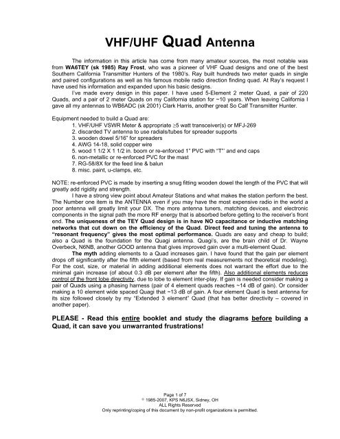
<strong>VHF</strong>/<strong>UHF</strong> <strong>Quad</strong> <strong>Antenna</strong><br />
The information in this article has come from many amateur sources, the most notable was<br />
from WA6TEY (sk 1985) Ray Frost, who was a pioneer of <strong>VHF</strong> <strong>Quad</strong> designs and one of the best<br />
Southern California Transmitter Hunters of the 1980’s. Ray built hundreds two meter quads in single<br />
and paired configurations as well as his famous mobile radio direction finding quad. At Ray’s request I<br />
have used his information and expanded upon his basic designs.<br />
I’ve made every design in this paper. I have used 5-Element 2 meter <strong>Quad</strong>, a pair of 220<br />
<strong>Quad</strong>s, and a pair of 2 meter <strong>Quad</strong>s on my California station for ~10 years. When leaving California I<br />
gave all my antennas to WB6ADC (sk 2001) Clark Harris, another great So Calf Transmitter Hunter.<br />
Equipment needed to build a <strong>Quad</strong> are:<br />
1. <strong>VHF</strong>/<strong>UHF</strong> VSWR Meter & appropriate ≥5 watt transceiver(s) or MFJ-269<br />
2. discarded TV antenna to use radials/tubes for spreader supports<br />
3. wooden dowel 5/16” for spreaders<br />
4. AWG 14-18, solid copper wire<br />
5. wood 1 1/2 X 1 1/2 in. boom or re-enforced 1” PVC with “T”’ and end caps<br />
6. non-metallic or re-enforced PVC for the mast<br />
7. RG-58/8X for the feed line & balun<br />
8. misc. paint, u-clamps, etc.<br />
NOTE: re-enforced PVC is made by inserting a snug fitting wooden dowel the length of the PVC that will<br />
greatly add rigidity and strength.<br />
I have a strong view point about Amateur Stations and what makes the station perform the best.<br />
The Number one item is the ANTENNA even if you may have the most expensive radio in the world a<br />
poor antenna will greatly limit your DX. The more antenna tuners, matching devices, and electronic<br />
components in the signal path the more RF energy that is absorbed before getting to the receiver’s front<br />
end. The uniqueness of the TEY <strong>Quad</strong> design is in have NO capacitance or inductive matching<br />
networks that cut down on the efficiency of the <strong>Quad</strong>. Direct feed and tuning the antenna to<br />
“resonant frequency” gives the most optimal performance. <strong>Quad</strong>s are easy and cheap to build;<br />
also a <strong>Quad</strong> is the foundation for the Quagi antenna. Quagi’s, are the brain child of Dr. Wayne<br />
Overbeck, N6NB, another GOOD antenna that gives improved gain over a multi-element <strong>Quad</strong>.<br />
The myth adding elements to a <strong>Quad</strong> increases gain. I have found that the gain per element<br />
drops off significantly after the fifth element (based from real measurements not theoretical modeling).<br />
For the cost, size, or material in adding additional elements does not warrant the effort due to the<br />
minimal gain increase (of about 0.3 dB per element after the fifth). Also additional elements reduces<br />
control of the front lobe directivity, due to lobe to element inter-play. If gain is needed consider making a<br />
pair of <strong>Quad</strong>s using a phasing harness (pair of 4 element quads reaches ~14 dB of gain). Or consider<br />
making a 10 element wide spaced Quagi that ~13 dB of gain. A four element <strong>Quad</strong> is best antenna for<br />
its size followed closely by my “Extended 3 element” <strong>Quad</strong> (that has better directivity – covered in<br />
another paper).<br />
PLEASE - Read this entire booklet and study the diagrams before building a<br />
<strong>Quad</strong>, it can save you unwarranted frustrations!<br />
Page 1 of 7<br />
© 1985-2007, KPS N6JSX, Sidney, OH<br />
ALL Rights Reserved<br />
Only reprinting/coping of this document by non-profit organizations is permitted.
<strong>Quad</strong> Dimension Formulas<br />
Element Formula Data<br />
Reflector 1030 / F (in MHz) = A’<br />
Driver 1005 / F (in MHz) = B’<br />
Director 1 975 / F (in MHz) = C’<br />
Director x 920 / F (in MHz) = D’<br />
Circumference of <strong>Quad</strong> wire loop is ((A or B or C or D) * 0.97(VF)) *12 (inches) = Zt<br />
Distance from center of the boom to wire support on spreader is (1.414213 * (Z/4)) / 2 = Y<br />
Velocity Factor = 0.97 (for solid 14-20 gauge copper wire). Z = Zt / 4<br />
A = metal tubing (TV aerial radials) 3/8" O.D. about 14-20” long)<br />
B = Wood doweling 5/16" - insulated spreaders<br />
C = boom<br />
Element wire - #18 solid enameled - strip ends before soldering<br />
Basic <strong>Quad</strong> Dimensions<br />
Elements Z Y Zt Spacing Bazooka<br />
.<br />
146.000 MHz.<br />
reflector 20.5 14.5 82 12<br />
driver 20 14 80 10 13.25<br />
director 1 19.4 13.75 77.6 9.0<br />
director x 18.3 13 73.2 9.0<br />
224.000 MHz.<br />
reflector 13.4 9.5 53.5 7.7<br />
driver 13.1 9.23 52.2 6.5 8.7<br />
director 1 12.7 9.0 50.7 6.1<br />
director x 12.0 8.5 47.8 6.1<br />
446.000 MHz.<br />
reflector 6.7 4.7 26.9 3.9<br />
driver 6.6 4.7 26.2 3.3 4.3<br />
director 1 6.4 4.5 25.5 3.1<br />
director x 6.0 4.2 24.0 3.1<br />
Page 2 of 7<br />
© 1985-2007, KPS N6JSX, Sidney, OH<br />
ALL Rights Reserved<br />
Only reprinting/coping of this document by non-profit organizations is permitted.
How to build a QUAD (in brief)<br />
These brief statements are to supplement the illustrations & diagrams.<br />
1. Tune up should be conducted with as little surrounding metal as possible and with the quad pointing<br />
away from any near structures. Study all illustrations before proceeding.<br />
2. Make the Bazooka Balun. Firmly tape the coax to the spreader, boom, and mast. The feed point is on<br />
the horizontal spreader for vertical polarization.<br />
3. Before tuning install all metal spreader supports, metal mast, and metal hardware that you are going<br />
to use. (This allows you to tune/compensate for any antenna RF pattern anomalies generated by metal<br />
in the near filed radiation area.)<br />
4. Construct the Reflector and Driver - first - add about 8 inches of wire to the Zt dimensions.<br />
Make the isolation spreader for the Driven element - see <strong>Quad</strong> Feed Point diagram.<br />
Place all the spreaders into the Reflector and Driven element holding tubes - measure a place<br />
all the spreaders at the proper dimensions.<br />
NOTE: I use electrical tape or lightly crimp the metal tube at the metal tube to wooden dowel<br />
intersecting point to hold the dimension.<br />
Adjust the driver feed points by increasing or decreasing the Reflector overall wire length. This<br />
allows you to obtain the lowest VSWR reading at the designed frequency.<br />
HINT: Adjust the Driver for the best VSWR and then trim with the Reflector circumference dimension...<br />
then back to the Driver and to re-trim...etc.<br />
Expected nominal results: ONLY Reflector & Driver<br />
3 el <strong>Quad</strong> 3 el VSWR 3 el <strong>Quad</strong> 3 el VSWR<br />
144.100 1.7:1 221.000 1.7:1<br />
145.000 1.4:1 222.000 1.4:1<br />
145.500 1:1 222.500 1:1<br />
146.000 1:1 223.000 1:1<br />
146.500 1:1 223.500 1:1<br />
147.000 1:1 224.000 1:1<br />
147.995 1:1 224.980 1:1<br />
5. Install and solder the Director(s) to their specified dimensions. Measure and make the Director(s) a<br />
perfect diamond.<br />
HINT: Make the wire the Zt dimension and permanently solder the wire - then pull the spreaders out to<br />
make a tight diamond with no wire sag! Pin the dowels into the metal tubes will keep the shape for a<br />
long time.<br />
Note: VSWR will probably go up; so go back to step 4 and re-tune the Driver and Reflector to obtain the<br />
best VSWR.<br />
6. When VSWR is relatively low or as you desire solder and fasten down the Reflector. Recheck the<br />
VSWR and trim the Driver as necessary. Then solder and fasten down the Driver.<br />
Page 3 of 7<br />
© 1985-2007, KPS N6JSX, Sidney, OH<br />
ALL Rights Reserved<br />
Only reprinting/coping of this document by non-profit organizations is permitted.
Nominal results: full <strong>Quad</strong> all elements<br />
4 el <strong>Quad</strong> 4 el VSWR 4 el <strong>Quad</strong> 4 el VSWR<br />
144.100 2.3:1 221.000 2.3:1<br />
145.000 1.4:1 222.000 1.4:1<br />
145.500 1:1 222.500 1:1<br />
146.000 1:1 223.000 1:1<br />
146.500 1:1 223.500 1:1<br />
147.000 1:1 224.000 1:1<br />
147.995 1.2:1 224.980 1:1<br />
7. If you have a field strength meter or BETTER a distant visual repeater, adjust the invisible front main<br />
lobe for directivity. This is accomplished by moving the Driven element horizontal spreaders left or right<br />
to obtain maximum indication on the field strength or "S" meter while sighting down the vertical<br />
spreaders at the repeater antenna.<br />
NOTE: Your body being near the antenna can skew the radiated pattern. So move a few feet away from<br />
the antenna when making measurements.<br />
8. Measure, align, and set all spreader elements for a good diamond shape.<br />
9. The antenna is built; now preserve the antenna in any fashion you deem necessary for your weather<br />
environment.<br />
Recommendations: silicon caulk the coax on the driver feed connections, marine spar varnish over a<br />
coat of paint, peg the spreader wooden dowels if desired to increase stability.<br />
NOTE: the more metal on the spreaders the less dowel to treat. In Southern California the heat/<br />
wind/rain/smog weather antennas quickly.<br />
Page 4 of 7<br />
© 1985-2007, KPS N6JSX, Sidney, OH<br />
ALL Rights Reserved<br />
Only reprinting/coping of this document by non-profit organizations is permitted.
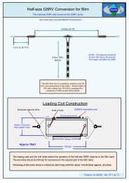
The BAZOOKA BALUN is the Secret for maximum efficiency of these <strong>Quad</strong>s! The bazooka<br />
balun is the only "Matching" device used. The bazooka balun is effectively an RF choke used to kill<br />
all/any returning RF energy from being conducted on the coax shield. The bazooka is the means of<br />
connecting an unbalanced (coax) line to a balanced antenna.<br />
The Bazooka Balun eliminates extraneous capacitive or inductive matching networks. This<br />
allows the <strong>Quad</strong> to be tuned to resonant frequency for maximum signal reception. As shown in the<br />
<strong>Quad</strong> Feed Point illustration the coax is soldered directly to the antenna driven element. This highly<br />
efficient coupling method conducts the most received RF signal into the receiver. Many of today’s<br />
antennas use the easy to make/tune loss’ee capacitive/inductive gamma type matches which consume<br />
some amount of antenna RF energy, thus, taking received signal from the radio RF amp/1 st mixer!<br />
Page 5 of 7<br />
© 1985-2007, KPS N6JSX, Sidney, OH<br />
ALL Rights Reserved<br />
Only reprinting/coping of this document by non-profit organizations is permitted.
Page 6 of 7<br />
© 1985-2007, KPS N6JSX, Sidney, OH<br />
ALL Rights Reserved<br />
Only reprinting/coping of this document by non-profit organizations is permitted.
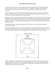
Pair of <strong>Quad</strong>s - Phasing Harness<br />
(approximately 14 dB gain)<br />
Each leg of coax from the antenna to the first barrel connector is of RG-58 coax with bazooka balun at a<br />
length of 66.25 inches each (each leg must be identical) and attached as shown for both antennas to be<br />
“IN” phase complementing one another.<br />
The phasing harness is of RG-59 coax (72 ohm) at 15 inches long.<br />
A minimum of 72” of horizontal spacing should be placed between two vertically polarized <strong>Quad</strong>s<br />
______________________________________________________________________________<br />
References:<br />
WA6TEY <strong>VHF</strong> <strong>Quad</strong> design<br />
73 <strong>VHF</strong> <strong>Antenna</strong> Handbook<br />
RSGB <strong>VHF</strong>-<strong>UHF</strong> Manual<br />
______________________________________________________________________________<br />
Page 7 of 7<br />
© 1985-2007, KPS N6JSX, Sidney, OH<br />
ALL Rights Reserved<br />
Only reprinting/coping of this document by non-profit organizations is permitted.