User's Manual Earth Ground Resistance Tester Kit Model 382252
User's Manual Earth Ground Resistance Tester Kit Model 382252
User's Manual Earth Ground Resistance Tester Kit Model 382252

You also want an ePaper? Increase the reach of your titles
YUMPU automatically turns print PDFs into web optimized ePapers that Google loves.
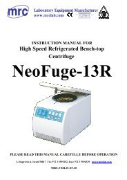
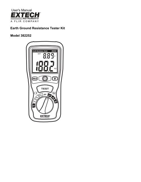
<strong>User's</strong> <strong>Manual</strong><br />
<strong>Earth</strong> <strong>Ground</strong> <strong>Resistance</strong> <strong>Tester</strong> <strong>Kit</strong><br />
<strong>Model</strong> <strong>382252</strong>
Introduction<br />
Congratulations on your purchase of the Extech <strong>382252</strong> <strong>Earth</strong> <strong>Ground</strong> <strong>Resistance</strong> <strong>Tester</strong><br />
<strong>Kit</strong>. This device can measure <strong>Earth</strong> <strong>Ground</strong> <strong>Resistance</strong> (in 3 ranges), <strong>Earth</strong> Voltage and<br />
<strong>Resistance</strong> (up to 200kΩ), and AC and DC voltage. This device was designed to meet<br />
EN61010-1 safety standards. Careful care and use of this meter will provide years of<br />
reliable service.<br />
Safety<br />
Please read the following safety information carefully before attempting to operate the<br />
meter and use the meter only as specified in this manual.<br />
Environmental safety information<br />
• Do not use meter outdoors when precipitation is likely<br />
• Installation Category III<br />
• Pollution degree 2<br />
• Altitude: 2000 meters max.<br />
• Ambient conditions: 32 to 104 o F (0 to 40 o C); RH: 80% max<br />
• Observe the following international safety warning symbols<br />
Safety Symbols<br />
Caution: Refer to this manual before using this meter<br />
Dangerous Voltages<br />
Meter is protected throughout by double or reinforced insulation<br />
Organizations that provide rules and guidelines for proper grounding<br />
• The National Electrical Code (NEC)<br />
• Underwriters Laboratories (UL)<br />
• National Fire Protection Association (NFPA)<br />
• American National Standards Institute (ANSI)<br />
• Occupational Safety Health Administration (OSHA)<br />
• Telecommunications Industry Standard (TIA)<br />
2<br />
<strong>Model</strong> <strong>382252</strong> Ver. 1.1 08/09
Meter Description<br />
1. Digital Display – See Display Description below<br />
2. HOLD key – Freezes measurement value on<br />
display<br />
3. 0 ADJ control- Adjusts Zero value on display<br />
4. Backlight key – Turns on Backlight<br />
5. TEST key – Enables <strong>Earth</strong> <strong>Resistance</strong> and <strong>Earth</strong><br />
Voltage Tests<br />
6. Function Selector switch – Selects desired range<br />
and function<br />
1<br />
2<br />
3<br />
4<br />
5<br />
6<br />
Top View<br />
1. VΩ/C Input<br />
2. P Input<br />
3. COM/E Input<br />
Display Description<br />
1 2 3<br />
1. Test status Icon<br />
2. Battery Charge indicator -<br />
1 2<br />
3. Voltage Unit indicator<br />
4. Audible Signal Icon<br />
5. Ω/kΩ Units Indicators<br />
6. Measurement Value<br />
9<br />
8<br />
7<br />
3<br />
4<br />
5<br />
7. AC/DC Voltage Indicators<br />
8. Low Battery Icon<br />
6<br />
9. HOLD Icon<br />
3<br />
<strong>Model</strong> <strong>382252</strong> Ver. 1.1 08/09
Operation<br />
0 Adjustment<br />
1. Connect the test leads to the meter as follows:<br />
a. Green lead to the 'E' terminal<br />
b. Yellow lead to the 'P' terminal<br />
c. Red lead to the 'C' terminal<br />
2. Set the function selector switch to the desired measurement range.<br />
3. Short the 3 test leads together.<br />
4. Press the TEST key.<br />
5. Use the 0 Adjust knob to adjust the displayed reading to 0Ω.<br />
6. Press to TEST key again to end the 0 adjustment process.<br />
Test Connection Diagram<br />
1. <strong>382252</strong> Meter<br />
2. Green Test Lead<br />
3. Yellow Test Lead<br />
4. Red Test Lead<br />
5. Existing <strong>Ground</strong><br />
6. P1 Auxiliary <strong>Earth</strong> Bar<br />
7. C1 Auxiliary <strong>Earth</strong> Bar<br />
1<br />
2 3 4<br />
5 6 7<br />
Test Preparation and Setup<br />
1. Connect the test leads to the meter (1) as follows:<br />
• Green lead (2) to the 'E' terminal<br />
• Yellow lead (3) to the 'P' terminal<br />
• Red lead (4) to the 'C' terminal<br />
2. Drive the Auxiliary <strong>Earth</strong> Bars P1 (6) & C1 (7) into the ground. Align the bars<br />
equidistant to the existing <strong>Earth</strong> ground connection and in a straight line as shown in<br />
the diagram above. If the auxiliary bars are placed in close proximity to the ground<br />
stake, measurement inaccuracies will result.<br />
3. Connect the clamp ends of the test leads to the <strong>Earth</strong> bars and existing ground<br />
connection as shown above:<br />
• Green lead (2) to the existing ground (5)<br />
• Yellow lead (3) to <strong>Earth</strong> Bar P1 (6)<br />
• Red lead (4) to the <strong>Earth</strong> Bar C1 (7)<br />
4<br />
<strong>Model</strong> <strong>382252</strong> Ver. 1.1 08/09
<strong>Earth</strong> Voltage Test<br />
1. Set the function on the selector’s switch to the EARTH VOLATAGE position.<br />
2. Confirm that the voltage measurement is less than 10V AC; otherwise accurate <strong>Earth</strong><br />
resistance measurements cannot be made. If voltage is present (higher than 10V AC),<br />
the source of the voltage must be found and corrected before testing can continue.<br />
3. Press to TEST key to end the test. Note the LCD reading.<br />
<strong>Earth</strong> <strong>Resistance</strong> Test<br />
1. Set the meter's function switch to the desired resistance range.<br />
2. Press the TEST button. . The “ “ icon will flash and the audible signal will sound.<br />
3. Note the displayed reading.<br />
4. If high resistance is detected, note the value and take appropriate steps to correct the<br />
ground connection if necessary.<br />
5. Press to TEST key to end the test.<br />
6. Readings of “1”…Ω are typical when the test leads are not connected to the meter.<br />
HOLD Function<br />
The Hold function freezes the latest measurement reading on the LCD.<br />
1. Press the HOLD key to freeze the reading on the LCD<br />
2. Press the HOLD key again to exit the HOLD function.<br />
3. The HOLD function does not retain measurement data if the meter is turned off.<br />
Backlight<br />
1. Press the “ “ key to turn on the backlight.<br />
2. The backlight will turn off after approximately 15 seconds.<br />
200kΩ <strong>Resistance</strong> Measurement<br />
1. Connect the red test lead to the VΩ connector and the black test lead to the COM<br />
connector.<br />
2. Set the function selector switch to the 200kΩ position.<br />
3. Connect the test probes to the circuit or component under test.<br />
4. Note the displayed <strong>Resistance</strong> value.<br />
AC Voltage Measurement<br />
1. Connect the red test lead to the VΩ connector and the black test lead to the COM<br />
connector.<br />
2. Set the function selector switch to the 750V AC position.<br />
3. Connect the test probes to the circuit under test.<br />
4. Note the displayed Voltage value.<br />
DC Voltage Measurement<br />
1. Connect the red test lead to the VΩ connector and the black test lead to the COM<br />
connector.<br />
2. Set the function selector switch to the 1000V DC position.<br />
3. Connect the test probes to the circuit under test.<br />
4. Note the displayed Voltage value.<br />
5<br />
<strong>Model</strong> <strong>382252</strong> Ver. 1.1 08/09
Maintenance<br />
Battery Replacement<br />
When the low battery icon ' ' appears on the LCD, the meter's batteries must be<br />
changed.<br />
1. Remove power and disconnect the test leads from the meter.<br />
2. Remove the tilt stand from the rear of the meter.<br />
3. Remove the 4 battery compartment screws with a Phillips head<br />
screwdriver.<br />
4. Remove the battery compartment cover and replace the six 1.5V 'AA'<br />
batteries.<br />
5. Affix compartment cover and tighten screw.<br />
6. Reattach the tilt stand.<br />
Cleaning and Storage<br />
Periodically wipe the meter's case with a damp cloth and mild detergent; do not use<br />
abrasives or solvents. If the meter is not to be used for a period longer than 60 days,<br />
remove the batteries and store them separately.<br />
Specifications<br />
General Specifications<br />
Measurements<br />
<strong>Earth</strong> <strong>Ground</strong> <strong>Resistance</strong> (in 3 ranges), <strong>Earth</strong> Voltage,<br />
AC Voltage to 750V and DC Voltage to 1000V<br />
Large LCD with dual display<br />
2.5 times per second<br />
Red lead: 50' (15m), Yellow: 33' (10m), Green: 16' (5m)<br />
'1' displayed as most significant digit<br />
Six 1.5V 'AA' batteries (included)<br />
Display<br />
Sampling Time<br />
Test lead length<br />
Over-range indication<br />
Power supply<br />
Low battery indication LCD displays icon<br />
Auto Power Off<br />
After approximately 15minutes of use<br />
Safety<br />
EN-61010-1 category III<br />
Weight<br />
24.7oz. (700g) with batteries<br />
Dimensions<br />
7.9 x 3.62 x 2" (200 x 92 x 50 mm)<br />
Supplied accessories Multimeter Test leads (2), <strong>Earth</strong> <strong>Ground</strong> test leads (3),<br />
auxiliary earth bars (2), six 'AA' batteries, and carrying case<br />
Operating Conditions 32ºF to 104ºF (0ºC to 40ºC), with < 80% RH<br />
Storage Conditions 14ºF to 140ºF (-10ºC to 60ºC), with < 70% RH<br />
6<br />
<strong>Model</strong> <strong>382252</strong> Ver. 1.1 08/09
Measurement Specifications<br />
Measurement Range Resolution Accuracy<br />
<strong>Earth</strong> <strong>Ground</strong><br />
<strong>Resistance</strong><br />
<strong>Earth</strong> Voltage<br />
Frequency: 40 to<br />
500Hz<br />
20Ω 0.01Ω ± (2% reading + 10 digits)<br />
200Ω 0.1Ω<br />
2000Ω<br />
0 to 200VAC<br />
1Ω<br />
± (2% reading + 3 digits)<br />
0.1V ± (3% reading +3digits)<br />
<strong>Resistance</strong><br />
AC Voltage<br />
40 Hz to 400Hz<br />
DC Voltage<br />
0 to 200kΩ 0.1kΩ ± (1% reading +2 digits)<br />
Overload Protection: 250 Vrms<br />
0 to 750V 1V ± (1.2% reading +10 digits)<br />
Overload Protection: 750 Vrms, Input Impedance: 10MΩ<br />
0 to 1000V 1V ± (0.8% reading +3 digits)<br />
Overload Protection: 1000 Vrms, Input Impedance: 10MΩ<br />
7<br />
<strong>Model</strong> <strong>382252</strong> Ver. 1.1 08/09
Warranty<br />
EXTECH INSTRUMENTS CORPORATION (A FLIR COMPANY) warrants this instrument to<br />
be free of defects in parts and workmanship for one year from date of shipment (a six<br />
month limited warranty applies to sensors and cables). If it should become necessary to<br />
return the instrument for service during or beyond the warranty period, contact the<br />
Customer Service Department at (781) 890-7440 ext. 210 for authorization or visit our<br />
website www.extech.com for contact information. A Return Authorization (RA) number<br />
must be issued before any product is returned to Extech. The sender is responsible for<br />
shipping charges, freight, insurance and proper packaging to prevent damage in transit.<br />
This warranty does not apply to defects resulting from action of the user such as misuse,<br />
improper wiring, operation outside of specification, improper maintenance or repair, or<br />
unauthorized modification. Extech specifically disclaims any implied warranties or<br />
merchantability or fitness for a specific purpose and will not be liable for any direct, indirect,<br />
incidental or consequential damages. Extech's total liability is limited to repair or<br />
replacement of the product. The warranty set forth above is inclusive and no other<br />
warranty, whether written or oral, is expressed or implied.<br />
Calibration and Repair Services<br />
Extech offers repair and calibration services for the products we sell. Extech also<br />
provides NIST certification for most products. Call the Customer Service Department for<br />
information on calibration services available for this product. Extech recommends that<br />
annual calibrations be performed to verify meter performance and accuracy.<br />
<br />
Support line (781) 890-7440<br />
Technical support: Extension 200; E-mail: support@extech.com<br />
Repair & Returns: Extension 210; E-mail: repair@extech.com<br />
Product specifications subject to change without notice<br />
For the latest version of this User Guide, Software updates, and other<br />
up-to-the-minute product information, visit our website: www.extech.com<br />
Extech Instruments Corporation, 285 Bear Hill Road, Waltham, MA 02451<br />
Copyright © 2009 Extech Instruments Corporation (a FLIR company)<br />
All rights reserved including the right of reproduction in whole or in part in any form.<br />
8<br />
<strong>Model</strong> <strong>382252</strong> Ver. 1.1 08/09