ALMEMO® 5690-2M - MRC
ALMEMO® 5690-2M - MRC
ALMEMO® 5690-2M - MRC

Create successful ePaper yourself
Turn your PDF publications into a flip-book with our unique Google optimized e-Paper software.
____________________________<br />
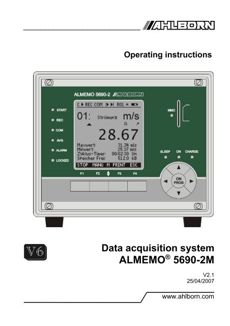
Operating instructions<br />
Data acquisition system<br />
ALMEMO ® <strong>5690</strong>-<strong>2M</strong><br />
V2.1<br />
25/04/2007<br />
www.ahlborn.com
1. Operating controls<br />
1. OPERATING CONTROLS<br />
1.1 Front panel<br />
(1) LCD<br />
Status bar<br />
C Cont. Measuring point scan<br />
© , ll Start / stop measuring<br />
REC Record to memory<br />
COM Measured value output<br />
l©, ©l Program start / end of measuring<br />
R01 Status of alarm relays<br />
* , * Lighting on, pause<br />
Battery operation / charge status<br />
13 lines for functions<br />
Function of keys F1, F2, F3, F4<br />
(2)Check lamps<br />
START Measuring operation started<br />
REC Measuring with results saved<br />
COM Measuring with output<br />
AVG Averaging<br />
ALARM Limit value exceeded<br />
Sensor breakage, LoBat<br />
LOCKED Keys locked<br />
(2)Check lamps<br />
ON Device is on.<br />
SLEEP Flashes in sleep mode.<br />
CHARGE Battery is being charged.<br />
Goes out as soon as fully<br />
charged.<br />
(3) Keypad<br />
F1 to F4<br />
ON<br />
PROG<br />
hold down)<br />
▲ , ▼ , ►<br />
◄<br />
Function keys (soft keys)<br />
Cursor block<br />
Switch on<br />
Program<br />
Switch OFF (press and<br />
Function selection, input<br />
Last menu<br />
(4) Slot, multimedia card<br />
MMC Slot for multimedia memory<br />
card<br />
2 ALMEMO ® <strong>5690</strong>-<strong>2M</strong>
Rear<br />
1.2 Rear<br />
(5) Module AP rechargeable<br />
battery (option)<br />
(a) Connection socket DC-A 12V<br />
Mains adapter (ZB 1212-NA6, 12V, 3A)<br />
(b) Check lamps<br />
DC-A Mains supply present<br />
CHARGE Battery is being charged.<br />
Goes out as soon as fully<br />
charged.<br />
(6) Module MM-A9<br />
Measuring circuit board<br />
ALMEMO<br />
(c) Measuring inputs M0 to M8<br />
M0 to M8 for all ALMEMO sensors<br />
M9 to M39 31 additional channels<br />
(d)Code switches<br />
G: Device address 0 to 99<br />
(e) Key ON/OFF, START/STOP<br />
No function<br />
(f) Output sockets A1, A2<br />
A1 Interface / optic fiber (ZA1909-DK5/L)<br />
RS 422 (ZA 5099-NVL/NVB)<br />
Ethernet (ZA 1945-DK)<br />
Bluetooth (ZA 1709-BTx)<br />
A2 Network cable (ZA1999-NK5/NKL)<br />
A1/A2 Trigger input (ZA 1000-ET/EK)<br />
Relay outputs (ZA 1000-EGK)<br />
Analog output 2 (ZA 1601-RK)<br />
(g) Connection socket DC 12V<br />
Mains adapter (ZB 1212-NA6, 12V, 3A)<br />
Cable, electr. isol. (ZB 3090-UK2, 10-30V)<br />
(h) Ground socket<br />
(i) Check lamps<br />
ON Device is on.<br />
START Measuring operation started<br />
REC Measuring with results saved<br />
COM Measuring with output<br />
ALARM Limit value exceeded<br />
Sensor breakage, LoBat<br />
ALMEMO ® <strong>5690</strong>-<strong>2M</strong> 3
1. Operating controls<br />
Extension of measuring points with selector switch boards<br />
(7) Module U-A10: selector switch board 10 ALMEMO sockets<br />
(j) Measuring inputs 0 to 9 x0 to x9 for all ALMEMO sensors<br />
x+10 to x+39 max. 30 additional channels<br />
(k) Code switch M: measuring point x: 10 to 90<br />
(8) Module U-MU: selector switch board 10x MU connector<br />
Measuring inputs x0 to x9 for analog sensors<br />
without power supply<br />
x+10 to x+39 max. 30 additional channels<br />
Code switch internal: measuring point x: 10 to 90 on board<br />
(9) Module U-TH: selector switch board 10 thermal sockets<br />
Measuring inputs x0 to x9 for 10 thermocouples<br />
x+10 to x+39 max. 30 additional channels<br />
Code switch internal: measuring point x: 10 to 90 on board<br />
(10) Module U-KS: selector switch board 2x5 clamp connectors<br />
Measuring inputs x0 to x9 for analog sensors<br />
without power supply<br />
x+10 to x+39 max. 30 additional channels<br />
Code switch internal: measuring point x: 10 to 90 on board<br />
4 ALMEMO ® <strong>5690</strong>-<strong>2M</strong>
Contents<br />
2. CONTENTS<br />
1. OPERATING CONTROLS ........................................................................ 2<br />
1.1 Front panel .......................................................................................... 2<br />
1.2 Rear ..................................................................................................... 3<br />
3. GENERAL .................................................................................................. 8<br />
3.1 Warranty .............................................................................................. 8<br />
3.2 Scope of delivery ............................................................................... 9<br />
3.3 How to deal with rechargeable batteries (option) ............................9<br />
3.4 Special notes on use .......................................................................... 9<br />
4. INTRODUCTION ...................................................................................... 10<br />
4.1 Functions of the ALMEMO <strong>5690</strong>-<strong>2M</strong> ............................................... 10<br />
4.1.1 Sensor programming.................................................................. 11<br />
4.1.2 Measuring operations ................................................................ 12<br />
4.1.3 Process control ......................................................................... 13<br />
5. INITIAL COMMISSIONING ...................................................................... 15<br />
6. POWER SUPPLY .................................................................................... 16<br />
6.1 Mains operation ................................................................................ 16<br />
6.2 External DC voltage supply ............................................................. 16<br />
6.3 Operation with rechargeable battery<br />
(only with module ES<strong>5690</strong>-AP)........................................................ 16<br />
6.4 Sensor supply .................................................................................. 17<br />
6.5 Switching ON / OFF, Reinitialization ............................................... 17<br />
6.6 Data buffering ................................................................................... 17<br />
7. CONNECTING THE TRANSDUCERS .................................................... 18<br />
7.1 Transducers ...................................................................................... 18<br />
7.2 Measuring inputs and additional channels .................................... 18<br />
7.3 Extending the measuring points ..................................................... 19<br />
7.4 Potential separation ......................................................................... 20<br />
8. DISPLAY AND KEYPAD ......................................................................... 22<br />
8.1 Display and menu selection ............................................................ 22<br />
8.2 Function keys ................................................................................... 23<br />
8.3 Status symbols in the display and status LEDs (2) .......................23<br />
8.4 Function selection ............................................................................ 24<br />
8.5 Data input .......................................................................................... 24<br />
9. MEASURING WITH THE MEASURING MENUS .................................... 25<br />
9.1 Measuring with a measuring point ................................................. 26<br />
9.1.1 Selecting a measuring point ...................................................... 26<br />
9.1.2 Peak value memory with date and time-of-day ......................... 26<br />
9.2 Measured value correction and compensation ............................. 27<br />
9.2.1 Set measured value to zero ...................................................... 27<br />
9.2.2 Zero-point adjustment ............................................................... 28<br />
9.2.3 Sensor adjustment for chemical sensors and probes ................28<br />
9.2.4 Two-point adjustment with setpoint entry .................................. 29<br />
9.2.5 Temperature compensation ..................................................... 30<br />
ALMEMO ® <strong>5690</strong>-<strong>2M</strong> 5
2. Contents<br />
9.2.6 Atmospheric pressure compensation ........................................ 30<br />
9.2.7 Cold junction compensation ...................................................... 31<br />
9.3 Measuring point scan and output ................................................... 32<br />
9.3.1 Once-only output / saving of all measuring points .....................32<br />
9.3.2 Cyclic output / saving of all measuring points ........................... 32<br />
9.3.3 Memory space, memory output, clearing the memory .............. 33<br />
9.3.4 Output menu functions............................................................... 33<br />
9.3.5 Displaying measured values as a line graph ............................. 34<br />
9.4 Averaging.......................................................................................... 35<br />
9.4.1 Smoothing out meas. val. by means of a sliding average ......... 36<br />
9.4.2 Averaging mode......................................................................... 36<br />
9.4.3 Averaging over individual manual measuring operations .......... 36<br />
9.4.4 Networked measuring ............................................................... 37<br />
9.4.5 Averaging over the measuring time ,measuring duration .......... 38<br />
9.4.6 Measuring time, measuring duration, timer................................ 38<br />
9.4.7 Averaging over the cycle ........................................................... 39<br />
9.4.8 Averaging over measuring points .............................................. 40<br />
9.4.9 Volume flow measurement......................................................... 41<br />
9.5 Display of several measuring points .............................................. 42<br />
9.5.1 Menu Multi-channel display and bar charts ............................... 42<br />
9.5.2 Differential measurement .......................................................... 42<br />
9.5.3 Menu Measuring points list ....................................................... 43<br />
9.6 Wizard menus for special measuring operations ..........................44<br />
9.6.1 Thermal coefficient .................................................................... 44<br />
9.6.2 Wet bulb globe temperature....................................................... 44<br />
9.7 User menus ...................................................................................... 45<br />
9.7.1 Functions................................................................................... 45<br />
9.7.2 Menu configuration ................................................................... 46<br />
9.7.3 Function printouts...................................................................... 47<br />
9.7.4 Programming via serial interface :.............................................. 48<br />
10. PROGRAMMING USING THE PROGRAMMING MENUS ......................49<br />
10.1 Times and cycles ........................................................................... 49<br />
10.1.1 Date and time-of-day ............................................................... 49<br />
10.1.2 Cycle with memory activation and output format...................... 49<br />
10.1.3 Measuring rate, continuous measuring point scan................... 50<br />
10.1.4 Start time Start date End time End date Measuring duration... 51<br />
10.2 Measured value memory ............................................................... 52<br />
10.2.1 Memory with multimedia card.................................................. 52<br />
10.2.2 Measured data, recording........................................................ 53<br />
10.2.3 Numbering of measuring operations........................................ 54<br />
10.2.4 Starting and stopping measuring operations............................ 54<br />
10.2.5 Scanning mode........................................................................ 54<br />
10.2.6 Memory output......................................................................... 56<br />
10.3 Sensor programming...................................................................... 58<br />
6 ALMEMO ® <strong>5690</strong>-<strong>2M</strong>
Contents<br />
10.3.1 Selecting the input channel...................................................... 58<br />
10.3.2 Measuring point designation ................................................... 58<br />
10.3.3 Averaging mode....................................................................... 59<br />
10.3.4 Locking the sensor programming............................................. 59<br />
10.3.5 Limit values.............................................................................. 60<br />
10.3.6 Scaling, Decimal point setting.................................................. 60<br />
10.3.7 Correction values..................................................................... 61<br />
10.3.8 Changing the units................................................................... 61<br />
10.3.9 Selecting the measuring range................................................. 61<br />
10.3.10 Function channels ................................................................. 64<br />
10.3.11 Special measuring ranges ,Linearization ,Multi-point calibration<br />
............................................................................................................ 66<br />
10.4 Special functions............................................................................. 67<br />
10.4.1 Print cycle factor ...................................................................... 67<br />
10.4.2 Minimum sensor power supply ................................................ 67<br />
10.4.3 Limit Value Responses ............................................................ 68<br />
10.4.4 Analog start and analog end ................................................... 69<br />
10.4.5 Output function ........................................................................ 69<br />
10.4.6 Reference channel 1................................................................ 70<br />
10.4.7 Reference channel 2 or multiplexer ......................................... 70<br />
10.4.8 Element flags........................................................................... 70<br />
10.5 Device configuration ...................................................................... 71<br />
10.5.1 Device designation................................................................... 71<br />
10.5.2 Device address and networking............................................... 71<br />
10.5.3 Baud rate, Data format............................................................. 72<br />
10.5.4 Language ................................................................................ 72<br />
10.5.5 Backlighting and contrast......................................................... 72<br />
10.5.6 Atmospheric pressure.............................................................. 72<br />
10.5.7 Hysteresis................................................................................ 73<br />
10.5.8 Operating parameters.............................................................. 73<br />
10.6 Output modules .............................................................................. 73<br />
10.6.1 Data cables ............................................................................. 74<br />
10.6.2 Relay trigger cable .................................................................. 74<br />
10.6.3 Analog output .......................................................................... 75<br />
10.7 Power supply menu........................................................................ 76<br />
10.8 Locking, calibration menu (option KL).......................................... 77<br />
11. TROUBLE-SHOOTING ............................................................................ 78<br />
12. ELECTROMAGNETIC COMPATIBILITY (EMC)...................................... 79<br />
13. APPENDIX................................................................................................ 80<br />
13.1 Technical data ................................................................................ 80<br />
13.2 Index................................................................................................. 82<br />
13.3 Your contact person....................................................................... 88<br />
ALMEMO ® <strong>5690</strong>-<strong>2M</strong> 7
3. General<br />
3. GENERAL<br />
Congratulations on your purchase of this new and innovative ALMEMO ® data<br />
acquisition system. Thanks to the patented ALMEMO ® connector the device<br />
configures itself automatically and thanks to the supplied AMR-Control software<br />
its operation should be fairly straightforward. The device can, however,<br />
be used with such a wide range of sensors and peripherals and offers many<br />
different special functions. You are advised therefore to properly familiarize<br />
yourself with the way the sensors function and with the device's numerous<br />
possibilities and take the time to carefully read these operating instructions<br />
and the appropriate sections in the ALMEMO ® Manual. This is absolutely necessary<br />
to avoid operating and measuring errors and to prevent damage to the<br />
device. To help you find the answers to your questions quickly and easily<br />
there is a comprehensive index at the end both of these instructions and of the<br />
Manual.<br />
3.1 Warranty<br />
Each and every device, before leaving our factory, undergoes numerous quality<br />
tests. We provide a guarantee, lasting two years from delivery date, that<br />
your device will function trouble-free. Before you send your device to us,<br />
please observe the advisory notes in Chapter 11. Trouble-shooting In the unlikely<br />
event that the device proves defective and you need to return it please<br />
wherever possible use the original packaging material for dispatch and enclose<br />
a clear and informative description of the fault and of the conditions in<br />
which it occurs.<br />
This guarantee will not apply in the following cases :<br />
● The customer attempts any form of unauthorized tampering and alteration<br />
inside the device.<br />
● The device is used in environments and conditions for which it is not<br />
suited.<br />
● The device is used with unsuitable power supply equipment and peripherals.<br />
● The device is used for any purpose other than that for which it is intended.<br />
● The device is damaged by electrostatic discharge or lightning.<br />
● The user fails to observe and respect the operating instructions.<br />
The manufacturer reserves the right to change the product's characteristics in<br />
the light of technical progress or to benefit from the introduction of new components.<br />
8 ALMEMO ® <strong>5690</strong>-<strong>2M</strong>
Scope of delivery<br />
3.2 Scope of delivery<br />
When you unpack the device check carefully for any signs of transport damage<br />
and that delivery is complete.<br />
Measuring instrument ALMEMO ® <strong>5690</strong>-<strong>2M</strong><br />
Multimedia card and USB card reader<br />
Mains adapter ZB1212-NA6 12V, 3A<br />
These operating instructions<br />
ALMEMO ® Manual<br />
CD with the AMR-Control software and various useful accessories<br />
In the event of transport damage please retain the packaging material and inform<br />
your supplier immediately.<br />
3.3 How to deal with rechargeable batteries (option)<br />
Usually when the device is delivered the batteries have not yet<br />
been charged. First of all therefore the batteries should be<br />
charged using the mains adapter provided; continue charging until<br />
the CHARGE lamp goes out.<br />
Rechargeable batteries must never be short-circuited or thrown<br />
on the fire.<br />
Rechargeable batteries are special waste and must not be discarded<br />
together with normal domestic waste.<br />
3.4 Special notes on use<br />
If the device is brought into the work room from a cold environment there is<br />
a risk that condensation might form on the electronics. In measuring operations<br />
involving thermocouples pronounced temperature changes may<br />
cause substantial measuring errors. You are advised therefore to wait until<br />
the device has adjusted to the ambient temperature before starting to use<br />
it.<br />
Before using the mains adapter make sure that the mains voltage is suitable.<br />
Be sure to observe the maximum load capacity of the sensor power supply.<br />
Sensors with integrated power supply are not electrically isolated from one<br />
another.<br />
Do not run sensor lines in the vicinity of high-voltage power cables.<br />
Before you touch any sensor lines, ensure that all static electricity has been<br />
discharged.<br />
ALMEMO ® <strong>5690</strong>-<strong>2M</strong> 9
4. Introduction<br />
4. INTRODUCTION<br />
The data acquisition system ALMEMO ® <strong>5690</strong>-<strong>2M</strong> is a new member in our family<br />
of unique measuring devices - all equipped with Ahlborn's patented<br />
ALMEMO ® connector system. The intelligent ALMEMO ® connector offers decisive<br />
advantages when connecting sensors and peripherals because all parameters<br />
are stored in an EEPROM located on the connector itself; repeat<br />
programming is thus no longer necessary.<br />
All sensors and output modules can be connected to all ALMEMO ® measuring<br />
instruments in the same way. Programming and functioning are identical for all<br />
units. The following points apply to all devices in the ALMEMO ® measuring<br />
system; these are described in detail in the ALMEMO ® Manual which is included<br />
in delivery with each device.<br />
Detailed explanation of the ALMEMO ® system (Manual Ch 1)<br />
Overview of the device functions and measuring ranges (Manual Ch 2)<br />
Basic principles, operation, and technical data for all sensors (Man. Ch 3)<br />
Options for connecting your own existing sensors (Manual Ch 4)<br />
All analog and digital output modules (Manual 5.1)<br />
Interface modules RS-232, optic fiber (Manual 5.2)<br />
The whole ALMEMO ® networking system (Manual 5.3)<br />
All functions and their operation via the interface (Manual Ch 6)<br />
Complete list of interface commands with all the print layouts (Man. Ch 7)<br />
The operating instructions you are now reading cover only those features and<br />
controls that are specific to this device. Many sections therefore also refer to<br />
the more detailed description in the Manual; (see Manual, Section xxx).<br />
4.1 Functions of the ALMEMO <strong>5690</strong>-<strong>2M</strong><br />
The data acquisition system ALMEMO ® <strong>5690</strong>-<strong>2M</strong> has basically 9 electrically<br />
isolated measuring inputs with over 70 measuring ranges - suitable for all<br />
ALMEMO ® sensors. This number can, using various selector switch boards,<br />
be extended to 99 inputs. To accommodate these various expansion stages<br />
the desktop housing is available in 32-DU / 84-DU sizes and a 19-inch rack is<br />
available. For operation purposes the device incorporates an LCD graphics<br />
display and a soft-key keypad with cursor block. The display can be adapted<br />
by means of configurable user menus to suit any application. Thanks to the<br />
real-time clock incorporated as standard and with a multimedia card the<br />
amount of data you can record is virtually endless. A variant is available with<br />
an integrated 512-KB EEPROM memory sufficient for approx. 100,000 measured<br />
values. There are two output sockets which can be used to connect any<br />
ALMEMO ® output modules, e.g. analog output, digital interface, trigger input,<br />
or alarm contacts. Several devices can be networked by simply linking them<br />
together via cable.<br />
The system is fed by default via a 12-V mains adapter. There is also the option<br />
of using a rechargeable battery module.<br />
10 ALMEMO ® <strong>5690</strong>-<strong>2M</strong>
Functions of the ALMEMO <strong>5690</strong>-<strong>2M</strong><br />
4.1.1 Sensor programming<br />
The measuring channels are programmed, completely and automatically, by<br />
the ALMEMO ® connectors. However, the user can easily supplement or modify<br />
this programming via the keypad or via the interface.<br />
Measuring ranges<br />
Appropriate measuring ranges are available for all sensors with a non-linear<br />
characteristic, e.g. 10 thermocouple types, NTC and PT100 probes, infrared<br />
sensors, and flow transducers (rotating vanes, thermoanemometers, Pitot<br />
tubes). For humidity sensors additional function channels are available for calculating<br />
humidity variables such as dew point, mixture ratio, vapor pressure,<br />
and enthalpy. Even complex chemical sensors are supported. Measured values<br />
from other sensors can also be acquired using the voltage, current, and<br />
resistance ranges with individual scaling in the connector. Existing sensors<br />
can also be used - so long as the appropriate ALMEMO ® connector is connected<br />
via its screw terminals. For digital input signals, frequencies, and pulses,<br />
adapter connectors are available with an integrated microcontroller. It is<br />
thus possible to connect virtually any sensor to any ALMEMO ® measuring instrument<br />
and to change sensors without the need for any extra settings.<br />
Function channels<br />
Maximum, minimum, average, and differential values from certain measuring<br />
points can be programmed as function channels, also internal channels, and<br />
can be processed and printed out like normal measuring points. There are also<br />
function channels available for special measuring tasks, e.g. to determine the<br />
temperature coefficient Q/∆T and wet bulb globe temperature.<br />
Units<br />
The 2-character units display can be adapted for each measuring channel so<br />
that both the display and the printout always indicate the correct units, e.g.<br />
when a transmitter is connected. Conversion between °C and °F is performed<br />
automatically.<br />
Measured value designation<br />
Each sensor is identified by means of a 10-character alphanumeric name. It is<br />
entered via the keypad or the interface and appears in the display, in the printout,<br />
or on the computer screen.<br />
Correction of measured values<br />
The measured value on each measuring channel can be corrected both in<br />
terms of zero-point and gain; this means that even sensors usually requiring<br />
initial adjustment (e.g. expansion, force, pH) can be freely interchanged. Zeropoint<br />
correction and, partly at least, gain adjustment can be performed at the<br />
touch of a button.<br />
Scaling<br />
The corrected measured value on each measuring channel can also be further<br />
scaled in terms of zero-point and gain - using the base value and factor. The<br />
decimal point position can be set by means of the exponent function. The scaling<br />
values can be calculated automatically by setting to zero and entering the<br />
ALMEMO ® <strong>5690</strong>-<strong>2M</strong> 11
4. Introduction<br />
nominal setpoint or via the scaling menu.<br />
Limit values and alarm<br />
Per measuring channel two limit values can be set (1 maximum and 1 minimum).<br />
In the event of one of these limit values being exceeded an alarm signal<br />
is output and relay output modules actuate the associated alarm contacts;<br />
these can be allocated individually to specific limit values. Hysteresis is set by<br />
default to 10 digits but this can be adjusted to any number between 0 and 99.<br />
The exceeding of a limit value can also be used to start or stop measured value<br />
recording automatically or via macros to initiate other specified actions.<br />
Sensor locking<br />
All sensor data stored in the connector EEPROM can be protected by means<br />
of a graduated locking function against undesired access.<br />
4.1.2 Measuring operations<br />
For each transducer up to four measuring channels are available; i.e. it is also<br />
possible to evaluate double sensors, individually scaled sensors, and sensors<br />
with function channels. You can move forwards or backwards from one measuring<br />
channel to the next using the keypad. The selected measuring point is<br />
by default assigned preferred status and is scanned at half the measuring rate;<br />
all other active channels are also scanned but in the background (semi-continuous<br />
mode). Data is output on the display and, if available, to the interface or<br />
to an analog output. To shorten the response time when there are many measuring<br />
points the measuring rate can be set to continuous and increased accordingly.<br />
Measured values<br />
The measured values of 1 to 20 measuring points can be indicated on the display<br />
using a variety of menus, some user-configurable, in three font sizes, and<br />
in the form of a bar chart or line graph. Measured values are acquired automatically<br />
with auto-zero and self-calibration; however, they can also be corrected<br />
and scaled arbitrarily as required. With most sensors a sensor breakage<br />
is detected automatically.<br />
Analog output and scaling<br />
By means of analog start and analog end any measuring point can be scaled<br />
in such a way that the resulting measuring range covers the full range of the<br />
bar chart or line graph or of an analog output (2 V, 10 V or 20 mA). At the<br />
analog output the device can output the measured value from any measuring<br />
point or a programmed value.<br />
Measuring functions<br />
With some sensors, to achieve optimal measured value acquisition, certain<br />
special measuring functions are required. Cold junction compensation is provided<br />
for thermocouples; temperature compensation is provided for dynamic<br />
pressure, pH, and conductivity probes; and atmospheric pressure compensation<br />
is provided for humidity sensors, dynamic pressure sensors, and O 2 sensors.<br />
On infrared sensors the parameters for zero-point correction and gain<br />
12 ALMEMO ® <strong>5690</strong>-<strong>2M</strong>
Functions of the ALMEMO <strong>5690</strong>-<strong>2M</strong><br />
correction are used as the background temperature and the emissivity factor.<br />
Maximum and minimum values<br />
Each measuring operation acquires and stores the maximum and minimum<br />
values with date and time-of-day. These values can then be displayed, printed<br />
out, or deleted from memory.<br />
Average value<br />
Measured values can be expressed as a sliding average obtained by continuous<br />
automatic smoothing or manually averaged over a certain period or cycle<br />
or over a series of individual measuring operations.<br />
4.1.3 Process control<br />
To record the measured values from all connected sensors in digital form measuring<br />
point scanning is performed continuously with measured value output<br />
according to a time-based process control. This may be per output cycle or, if<br />
really rapid results are required, at the measuring rate itself. The measuring<br />
operation can be started and stopped by means of the keyboard, the interface,<br />
an external trigger signal, the real-time clock, or by a specified limit value being<br />
exceeded.<br />
Date and time-of-day<br />
All measuring operations can be accurately logged using the real-time clock<br />
with date function or in terms of the pure measuring time. For the purposes of<br />
starting / stopping a measuring operation, the start / stop date and time-of-day<br />
can be programmed.<br />
Cycle<br />
The cycle can be programmed to any value between 00:00:01 (1 second) and<br />
59:59:59 hh:mm:ss. This function permits cyclic output of measured values to<br />
the interfaces or to the memory and provides cyclic calculation of the average<br />
value.<br />
Print cycle factor<br />
The print cycle factor can be used to limit data output from particular channels;<br />
this may be necessary in order to reduce excessive data flow especially while<br />
data is being saved.<br />
Averaging over measuring point scans<br />
The measured values from measuring point scans can be averaged either<br />
over the whole measuring duration or over the specified cycle. Function channels<br />
are available for the cyclic output and storage of these average values.<br />
Measuring rate<br />
On the ALMEMO ® <strong>5690</strong>-<strong>2M</strong> all measuring points are scanned at the measuring<br />
rate set (2.5, 10, 50, or 100 measuring operations per second). Recording<br />
can be accelerated if all measured values are stored to memory and / or output<br />
to the interface at the measuring rate.<br />
Measured value memory<br />
To save measured values there are two alternative methods.<br />
Normally a multimedia memory card is used as storage medium. This solution<br />
ALMEMO ® <strong>5690</strong>-<strong>2M</strong> 13
4. Introduction<br />
offers a virtually limitless memory capacity. With the memory card files can be<br />
read very quickly via any standard card reader; however, ring memory and selective<br />
readout are not possible.<br />
Option S is a 512-KB non-volatile EEPROM, sufficient for up to 100,000 measured<br />
values. This memory can be organized and configured in linear or ring<br />
form. For output via the interface it is possible to specify a selection according<br />
to either the time interval or the number assigned to the measuring operation.<br />
Numbering of measuring operations<br />
By entering a number, single scans or entire series of measuring operations<br />
can be identified and selectively read out from the memory.<br />
Control outputs<br />
Via the keypad and interface up to four output relays and analog outputs can<br />
be individually addressed.<br />
Operation<br />
All measuring and function values can be displayed in different menus on the<br />
dot matrix LCD screen. Three user menus can be individually configured from<br />
a range of nearly 50 functions for your specific applications. You can use texts,<br />
lines, and blank lines to arrange and format the layout in a style suited to your<br />
application. Nine keys (four of them soft keys) can be used to operate the device.<br />
This system also allows you to fully program the sensors, the device and<br />
the process control.<br />
Output<br />
All data logs, menu functions, saved measured values, and stored program<br />
parameters can be output to any peripheral equipment. Interfaces for RS-232,<br />
RS-422, and Ethernet are provided by the appropriate interface cables. Measured<br />
data can be output in list, column, or table format. Files in table format<br />
can be processed directly using any standard spreadsheet software. The print<br />
header can be programmed specifically for the company or your application.<br />
Networking<br />
All ALMEMO ® devices can be addressed and can be easily networked by<br />
simply linking them together via network cable or for longer distances via RS-<br />
422 network distributors.<br />
Software<br />
Each ALMEMO ® Manual is accompanied by the AMR-Control software package,<br />
which can be used to configure the measuring instrument and user<br />
menus, to program the sensors, and to read out from the measured value<br />
memory. Using the integrated terminal, measuring operations can also be performed<br />
online. The software package WIN-Control is provided for the purposes<br />
of measured value acquisition via networked devices, for graphical presentation,<br />
and for more complex data processing.<br />
14 ALMEMO ® <strong>5690</strong>-<strong>2M</strong>
Initial commissioning<br />
5. INITIAL COMMISSIONING<br />
Sensor connection : Plug in sensor at socket M0 to M8 (6c); see Section 7.<br />
Power supply : Via mains adapter to socket DC (6g); see 6.3, 6.1.<br />
Switch on : Press ON PROG key (3) on front panel; see 6.5.<br />
Automatic display of last measuring menu see Ch 9. Keys<br />
To activate MEASURING menus press<br />
< ESC > or F4<br />
e.g. select standard display menu; see 8.1 / ... ( F )<br />
To activate menu press<br />
<br />
Select measuring point (see 9.1.1) by means of keys : / ... ( M )<br />
To select max / min values function(see 8.4) press PROG , ...<br />
Clear max / min values (see 9.1.2 < CLR > or F1<br />
* ALMEMO <strong>5690</strong>-<strong>2M</strong> *<br />
±±±±±±±±±±±±±±±±±±±±±±±±±±±±±±±±±<br />
MEASURING Menus<br />
Standard display ©<br />
U1 Meas. value correction<br />
U2 Averaging<br />
U3 Volume flow<br />
Data logger<br />
Multi-channel display<br />
*List of measuring points<br />
Bar chart<br />
Line graph<br />
__________________________<br />
Menu1 PROGRAMMING Menus<br />
Menu2 ASSISTANT Menus<br />
C © REC COM l© ©l R01 * ´´´´´´µµµµ<br />
¯¯¯¯¯¯¯¯¯¯¯¯¯¯¯¯¯¯¯¯<br />
01: Velocity m/s<br />
æ » H º<br />
28.67<br />
Maximum value: 31.34 mls<br />
Minimum value: 25.37 mls<br />
Cycle-timer: 00:02:30 Un<br />
Memory free: 512.0 kB<br />
START MANU M PRINT ESC<br />
POFF *ON F MENU1 MENU2<br />
F1 F2 | F3 F4<br />
F1 F2 | F3 F4<br />
<br />
<br />
PROG <br />
PROG <br />
<br />
<br />
Output of measured values or memory via interface :<br />
- Connect peripheral device via data cable to socket A1 (6f); see Manual 5.2<br />
- On peripheral device set 9600 baud, 8 data bits, 1 stop bit, no parity.<br />
Once-only output / saving to memory see 9.3.1 < MANU > or F2<br />
Cyclic measuring operation : Select cycle timer : PROG , ...<br />
Enter cycle (hh:mm:ss); see 8.5<br />
Cycle timer: 00:05:00Sn<br />
Output format list ´ ´, Columns ´n´, Table ´t´ < FORM> or F3 ...<br />
Terminate programming<br />
< ESC> or F4<br />
Start / stop cyclic measuring operation; see 9.3.2 , or F1<br />
Output from memory to the printer or to the computer :<br />
Select Memory capacity free function by means of : PROG , ...<br />
Output memory; see 10.2.6<br />
< PRINT> or F3<br />
Clear the memory; see 10.2.6 < CMEM ><br />
ALMEMO ® <strong>5690</strong>-<strong>2M</strong> 15
6. Power supply<br />
6. POWER SUPPLY<br />
Power can be supplied to the instrument in any of the following ways :<br />
Mains adapter 12V, 3A<br />
ZB1212-NA6<br />
Electr. isol. power supply cable, 10 to 30 VDC, 0.25 A (ZB3090-UK)<br />
Electr. isol. power supply cable, 10 to 30 VDC, 1.25 A (ZB3090-UK2)<br />
Rechargeable battery module, NiMH 9.6 V / 1600 mAh (ES<strong>5690</strong>-AP)<br />
See product overview, Annex 14 and the following chapters.<br />
6.1 Mains operation<br />
To power the device from the mains use the mains adapter provided, 12 V/3A<br />
(ZB1212-NA6). The mains adapter must be connected to the DC socket (6g)<br />
and locked by twisting to the right.<br />
If necessary the device can also be grounded via the bare socket (6h) (e.g.<br />
protective ground connector).<br />
6.2 External DC voltage supply<br />
The DC socket (6g) can also be used to connect another DC voltage, 10 to 13<br />
V (minimum 200 mA). For this connection use a cable with 2 banana plugs<br />
(ZB 5090-EK). If, however, the power supply has to be electrically isolated<br />
from the transducers or if a larger input voltage range, 10 to 30 V, is required,<br />
then electrically isolated supply cable (ZB 3090-UK) must be used (or ZB<br />
3090-UK2 with the rechargeable battery module). It will then be possible to<br />
use the measuring instrument in a 12-volt or 24-volt on-board supply system.<br />
6.3 Operation with rechargeable battery<br />
(only with module ES<strong>5690</strong>-AP)<br />
For mains-independent operation the system must be equipped with module<br />
AP with eight NiMH rechargeable batteries (9.6 V / 1600 mAh). At a current<br />
consumption of approx. 40 mA this will give an operating time of approx. 40<br />
hours. To prolong the operating time for the purposes of long-term recording<br />
the device can be left in SLEEP mode; (see 10.2.5). The operating voltage<br />
can be checked in the power supply menu (see 10.7); this gives you a basis<br />
for estimating the remaining operating time. When the remaining battery capacity<br />
drops to approx. 10%, the ´´µµµµµµµµµ symbol in the status bar of the display<br />
will start flashing; as soon as this happens the batteries must be recharged. If<br />
the batteries are completely discharged the device will switch off to avoid the<br />
risk of critically low discharge. The measured data and time-of-day will, however,<br />
be retained; see 6.6. The NiMH rechargeable batteries can in fact be<br />
recharged at any time and in any charge status using the intelligent charge circuitry.<br />
To charge the batteries the mains adapter,12V, 3A (ZB1212-NA6) must<br />
be connected to socket DC-A (5a) on the battery module. The "CHARGE" lamp<br />
should then light up indicating that the batteries are being recharged. After ap-<br />
16 ALMEMO ® <strong>5690</strong>-<strong>2M</strong>
Operation with rechargeable battery<br />
(only with module ES<strong>5690</strong>-AP)<br />
prox. 3.5 hours the batteries are fully recharged and the LED goes out again.<br />
After a certain period the batteries are recharged again; the charge circuitry<br />
then switches over to trickle charge. The mains adapter can thus be left permanently<br />
connected to the measuring instrument in buffer mode without risk of<br />
overcharging the batteries. If you prefer not to recharge the batteries, e.g. to<br />
prevent the device from warming up during thermocouple measurement, you<br />
can connect the mains unit to the DC socket (6g).<br />
6.4 Sensor supply<br />
At the terminals + (plus) and – (minus) in the ALMEMO ® connector there is, for<br />
mains operation, a sensor supply voltage, approx. 12 V, 400 mA, available<br />
(self-healing fuse, 500 mA). During battery operation the battery voltage is<br />
available, 9 to 11 V. Other voltages (12, 15, or 24 V or references for a potentiometer<br />
and strain gauge) can be obtained using special connectors; (see<br />
Manual 4.2.5 and 4.2.6).<br />
6.5 Switching ON / OFF, Reinitialization<br />
To switch the device ON press the ON-PROG key (3); the ´ON´ lamp should<br />
light up as verification.<br />
To switch the device OFF press the ON-PROG key and hold down for approx.<br />
1 second. After the device is switched off the real-time clock continues to run<br />
and all saved values and settings are retained intact; (see 6.6).<br />
If the device behaves abnormally as the result of interference (e.g. electrostatic<br />
or mains failure), you are advised try first of all to clear the problem simply<br />
by reinitializing, i.e. switching off and then on again.<br />
If this does not help then you can reinitialize the device. To activate Reset<br />
press F1 r when switching on. To restore all device programming (including<br />
times, device designation, user menus, etc.) to the factory default settings<br />
press F4 r when switching on. Only the programming of the sensors in the<br />
ALMEMO ® connectors remains unaffected.<br />
6.6 Data buffering<br />
The sensor's programming is stored in the EEPROM on the sensor connector<br />
and the device's calibration and programmed parameters are stored in the<br />
EEPROM on the instrument itself, both on a fail-safe basis. The memory data<br />
is also saved in non-volatile EEPROMs. The date and time-of-day are buffered<br />
by a dedicated lithium battery; even when the device is switched off and without<br />
batteries this data is retained intact for years.<br />
ALMEMO ® <strong>5690</strong>-<strong>2M</strong> 17
7. Connecting the transducers<br />
7. CONNECTING THE TRANSDUCERS<br />
Virtually any ALMEMO ® sensor can be connected to the input sockets on<br />
ALMEMO ® modules types (6) and (7). To connect your own existing sensors<br />
you simply need the appropriate ALMEMO ® connector. Other compact modules<br />
are described below.<br />
7.1 Transducers<br />
The ALMEMO ® Manual includes detailed descriptions of the comprehensive<br />
ALMEMO ® range of sensors (see Manual Ch 3) and instructions for connecting<br />
your own existing sensors to ALMEMO ® instruments (see Manual Ch 4).<br />
All standard sensors with an ALMEMO ® connector usually have the measuring<br />
range and units already programmed and can thus be connected to any input<br />
socket without further adjustment. A mechanical coding system ensures that<br />
sensor and output modules can only be connected to the correct sockets. All<br />
ALMEMO ® connectors incorporate two snap-lock levers; these snap into position<br />
as soon as the connector is inserted into the socket, thus preventing unintended<br />
disconnection if the cable is accidentally pulled. To withdraw the connector,<br />
both these levers must be pressed in at the sides.<br />
7.2 Measuring inputs and additional channels<br />
Measuring circuit board MM-A9 has 9 input sockets (6c) to which initially measuring<br />
channels M0 to M8 are allocated. However, ALMEMO ® sensors can, if<br />
required, provide up to 4 channels with 9 input sockets each so that altogether<br />
36 channels are available. The additional channels can be used in particular<br />
for humidity sensors with four measuring variables (temperature / humidity /<br />
dew point / mixture ratio) or for function channels. Each sensor can if necessary<br />
be programmed with several measuring ranges or scaling settings; and<br />
two or three sensors, if pin assignment so permits, can be combined in a single<br />
connector (e.g. rH / NTC, mV / V, mA / V, etc.). The additional measuring<br />
channel numbers per connector go up in steps of 10 (e.g. the first sensor has<br />
channels M0, M10, M20, M30, the second sensor has channels M1, M11,<br />
M21, M31 etc.).<br />
Device-internal channels<br />
A further innovation on this device is its four additional device-internal channels.<br />
The first of these M9 is programmed by default as differential channel M1<br />
– M0. This only applies, however, if there are two sensors with the same units<br />
and same decimal point position connected at measuring points M0 and M1.<br />
However, all four channels can be programmed with any other function channels<br />
(e.g. U-Bat, cold junction compensation, average, volume flow, etc.); (see<br />
Manual 6.3.4). The reference channels used are by default Mb1 = M1 and<br />
Mb2 = M0 but this can be modified (see Manual 6.3.4).<br />
The advantage of device-internal channels is that when using several sensors<br />
for the same application these sensors do not have to be reprogrammed and<br />
18 ALMEMO ® <strong>5690</strong>-<strong>2M</strong>
Measuring inputs and additional channels<br />
can be exchanged without losing the function channels. However, if the whole<br />
application operates with just one sensor, then programming on the sensor itself<br />
makes more sense.<br />
On the measuring circuit board this gives the following channel assignment:<br />
Sensor channels<br />
Device internal channels<br />
4. Channel<br />
3. Channel<br />
2. Channel<br />
1. Channel<br />
30<br />
20<br />
10<br />
00<br />
31<br />
21<br />
11<br />
01<br />
32<br />
22<br />
12<br />
02<br />
33<br />
23<br />
13<br />
03<br />
34<br />
24<br />
14<br />
04<br />
35<br />
25<br />
15<br />
05<br />
36<br />
26<br />
16<br />
06<br />
37<br />
27<br />
17<br />
07<br />
38<br />
28<br />
18<br />
08<br />
39<br />
29<br />
19<br />
09<br />
Difference M01-M00<br />
M0 M1 M2 M3 M4<br />
M5 M6 M7 M8<br />
7.3 Extending the measuring points<br />
To extend the measuring points, up to 9 passive selector switch boards can<br />
be used; however, the total number of measuring channels is limited to maximum<br />
100.<br />
The master measuring circuit board MM-A09 (6) can also drive up to 9 selector<br />
switch boards with 10 inputs each (7j), and these can in turn be<br />
switched by photovoltaic relays. The sensor and channel number of each<br />
module can be adapted to individual requirements by configuring the measuring<br />
point numbering and thus the channel number of the modules by means of<br />
a code switch (7k). This code switch defines the measuring point number of<br />
the first measuring point of each module and thus also the channel number of<br />
the previous module. This measuring point number must logically be set between<br />
10 and 40 measuring points higher than the previous module and accordingly<br />
the channel number of the previous module will be limited to 10 to 40<br />
measuring points. Multi-channel sensors should therefore be collected as far<br />
as possible in one module. 99 sensors can only be collected in 10 modules if<br />
the channel number of each module is limited to 10, i.e. the measuring point<br />
number goes up by 10 each time. The time taken for a measuring point scan<br />
increases in proportion to the number of measuring channels.<br />
1. With selector switch board U-A10 (7) the number of measuring points is<br />
extended each time by 10 electrically isolated ALMEMO ® inputs for all<br />
ALMEMO ® sensors. In the housing each module occupies 2 plug-in slots.<br />
For the purposes of thermocouple measurement each module is equipped<br />
with 2 cold junction sensors whose value is interpolated for each measuring<br />
point. The measuring time involved will affect the total sampling rate.<br />
2. Selector switch board U-MU (8) occupies only 1 plug-in slot but it too has<br />
10 inputs led out to a 64-contact socket strip. The sensors are connected<br />
via a 10-fold connector (ZA <strong>5690</strong>-MU) each with four screw terminals A, B,<br />
ALMEMO ® <strong>5690</strong>-<strong>2M</strong> 19
7. Connecting the transducers<br />
C, D, in the same way as any standard ALMEMO ® connector; (see Manual<br />
4.1). Sensors requiring a power supply or an ALMEMO ® connector with<br />
special interface circuitry (e.g. humidity sensors, rotating vanes, etc.) cannot<br />
be connected in this way. The new connector ZA <strong>5690</strong>-MU with a larger<br />
EEPROM now permits 4 channels per sensor, i.e. 40 channels altogether;<br />
on the old connector ZA 5590-MU there are only 10 channels available.<br />
Measuring point numbering is as described above, namely by means of a<br />
code switch internally on the board. For this purpose the module must be<br />
withdrawn and the number on the switch multiplied by 10 (4 = measuring<br />
point 40). All sensors can be programmed individually but their programming<br />
data is all saved together in a common EEPROM located in the connector.<br />
A cold junction sensor is also provided for thermocouples. Two limit<br />
value relays, operating separately for maximum and minimum, can be contacted<br />
in the connector; these can only be used with an appropriate selector<br />
switch board option.<br />
3. Selector switch board U-TH (9) has 10 inputs for thermocouples with a<br />
thermal connector. The sensor data is saved to an EEPROM on the board;<br />
automatic sensor recognition is therefore not possible. Measuring point<br />
numbering is by means of the code switch internally on the board (see<br />
above). This module occupies only 1 plug-in slot but if arranged in series<br />
one dummy panel must be inserted between in order to operate the connector.<br />
4. Selector switch board U-KS (10) also has 10 inputs; these are led directly<br />
onto two 20-contact plug connectors with terminals. Sensors can be connected<br />
via terminals A, B, C, D, with the usual wiring arrangement. In order<br />
to feed in the wires the outside connectors must be opened by inserting a<br />
narrow screw-driver in the inside holes. Or alternatively the cards are available<br />
with shunts for 20-mA signals (terminals A and B, ´mA ´ or ´% ´) or<br />
with dividers for 10-V signals (terminals A and C, ´mV 2´). This module is<br />
only suitable for thermocouples if these are connected with copper wires<br />
via an isothermal block with integrated cold junction sensors; (see Manual<br />
6.7.3). The sensor data is saved to an EEPROM on the board; automatic<br />
sensor recognition is therefore not possible. Measuring point numbering is<br />
by means of the code switch internally on the board (see above). This module,<br />
similarly, occupies 1 plug-in slot only.<br />
7.4 Potential separation<br />
When organizing a properly functioning measuring setup it is very important to<br />
ensure that no equalizing current can flow between sensors, power supply,<br />
and peripherals. This will be the case so long as all points lie at the same potential<br />
or unequal potentials are electrically isolated.<br />
The analog inputs are electrically isolated from one another by means photovoltaic<br />
relays. A new feature on this device is the additional separation of the<br />
20 ALMEMO ® <strong>5690</strong>-<strong>2M</strong>
Potential separation<br />
Sensors<br />
M2<br />
M1<br />
M0<br />
electr. isol.<br />
U+<br />
U-<br />
B<br />
A<br />
S<br />
ADC<br />
DC<br />
DC<br />
CPU<br />
Data cable<br />
measuring inputs from CPU and power supply. Between all inputs and outputs<br />
(even the analog output cables which are not electrically isolated) the maximum<br />
potential difference permitted is 50 V. The voltage at the measuring inputs<br />
themselves must not exceed 12 V (between B, C, D, and A).<br />
However, some components are not electrically isolated, namely all sensors<br />
connected to the same internal power supply ±U or combined sensors<br />
within one connector. For these sensors the electrical isolation may have to<br />
be disabled by means of relay S (see above) or by wire jumper; some inputs<br />
would otherwise be left without reference potential. The relay is set automatically<br />
by element flag 5 ´ISO OFF´ the first time it is connected; (see Manual<br />
6.10.3). However, with certain connectors (especially divider connectors without<br />
power supply) element flag 5 should be checked and if necessary corrected.<br />
These sensors must themselves be isolated or the device must be operated<br />
with an electrically isolated power supply (mains adapter or connecting cable<br />
ZA3690-UK with DC/DC converter).<br />
Data and trigger cables are also isolated by means of optocouplers.<br />
DC<br />
DC<br />
DC<br />
Power supply<br />
AC<br />
10..30V=<br />
230V≈<br />
ALMEMO ® <strong>5690</strong>-<strong>2M</strong> 21
8. Display and keypad<br />
8. DISPLAY AND KEYPAD<br />
8.1 Display and menu selection<br />
The display (1) of measuring system ALMEMO <strong>5690</strong>-<strong>2M</strong> consists of a dot matrix<br />
LCD display with 128x128 pixels, or 16 rows of 8 pixels. For acquiring<br />
measured values using the appropriate functions, for programming the process<br />
control, and for setting the sensors and device parameters there are<br />
three menu categories available, namely measuring menus (see Ch 9), programming<br />
menus (see Ch 10), and wizard menus accessed via the selection<br />
menus. Of the 9 measuring menus 3 are ´User´ menus, U1, U2, U3; these can<br />
be freely configured by the user (see 9.7).<br />
* ALMEMO <strong>5690</strong>-2 *<br />
±±±±±±±±±±±±±±±±±±±±±±±±±±±±±±±±±±<br />
MEASURING Menus<br />
Standard display ©<br />
U1 Meas. value correction<br />
U2 Averaging<br />
U3 Volume flow<br />
Data logger<br />
Multi-channel display<br />
*List of measuring points<br />
Bar chart<br />
Line graph<br />
_____________________<br />
* ALMEMO <strong>5690</strong>-2 *<br />
±±±±±±±±±±±±±±±±±±±±±±±±±±±±±±±±±<br />
PROGRAMMING-Menus:<br />
Times, cycles<br />
Recording to memory ©<br />
* ALMEMO <strong>5690</strong>-2 *<br />
±±±±±±±±±±±±±±±±±±±±±±±±±±±±±±±±±±±±±±±±±±±±±<br />
ASSISTANT-Menus:<br />
Output from memory Start-Stop<br />
Sensor programming Averaging ©<br />
...Special functions Volume flow<br />
Device configuration Function channels<br />
Output modules<br />
Scaling<br />
Power supply<br />
Sensor adjustment<br />
Menu1 PROGRAMMING Menus<br />
Limits, Alarm<br />
Menu2 ASSISTANT Menus ____________________ Analog output<br />
Menu1 ASSISTANT-Menus Thermal coefficient<br />
POFF *ON F MENU1 MENU2<br />
Menu2 MEASURING-Menus Wet bulb globe temperature<br />
±±±±±±±±±±±±±±±±±±±±±±±±±±±±±±±±±±±±±±±±±±±±±±±<br />
POFF *ON F MENU1 MENU2<br />
Menu1 MEASURING-Menus<br />
Menu2 PROGRAMMIER-Menus<br />
POFF *ON F MENU1 MENU2<br />
Display menu selection by means of<br />
<br />
To select desired menu selection press<br />
or <br />
Display backlighting can be switched on in 3 levels (see 10.5.5) < ON > ...<br />
To switch off the device press<br />
or ON<br />
(press and hold down)<br />
To select the menu press or ...<br />
To activate the selected menu press or PROG<br />
To return to the measuring menu last used press<br />
<br />
To return to the programming menu last used press press again<br />
To return to menu selection press<br />
<br />
<br />
You can program the device designation in the header line (see<br />
10.5.1) and the titles of the user menus (see 9.7).<br />
22 ALMEMO ® <strong>5690</strong>-<strong>2M</strong>
8.2 Function keys<br />
The function of keys F1 to F4 (3) can be different<br />
in each of the various menus. The function<br />
is indicated as an abbreviation in the bottom<br />
line of the display (soft keys). In the instructions<br />
and documentation these soft key<br />
abbreviations are shown in angle brackets,<br />
e.g. .<br />
Various status symbols are displayed next to<br />
the measured value; (see below).<br />
In the standard display (on the right) the following<br />
keys are available.<br />
Function keys<br />
C © REC COM l© ©l R01 * ´´´´´´µµµµ<br />
¯¯¯¯¯¯¯¯¯¯¯¯¯¯¯¯¯¯¯¯¯<br />
01: Velocity m/s<br />
æ » H º<br />
28.67<br />
Maximum value: 31.34 mls<br />
Minimum value: 25.37 mls<br />
Cycle-timer: 00:02:30 Un<br />
Memory free: 512.0 kB<br />
START MANU M PRINT ESC<br />
F1 F2 | F3 F4<br />
Measuring point selection using the cursor keys (3) (M in middle) o. ...<br />
Start a cyclic measuring operation or F1<br />
Stop a cyclic measuring operation or F1<br />
Once-only manual output / saving of all measured values<br />
or F2<br />
Output menu functions via the interface or F3<br />
Return to menu selection<br />
< ESC > or F4<br />
8.3 Status symbols in the display and status LEDs (2)<br />
Checking the device status<br />
Status bar LEDs<br />
Continuous measuring point scan C<br />
Measuring stopped or started ll or © START<br />
Measuring point scan started with data saving REC REC<br />
Measuring point scan started with output to interface COM COM<br />
Start time or end time of meas. operation programmed l© or ©l<br />
Status of relay (external output module) off / on R-- or R01<br />
Keypad operation restricted by locking LOCKED<br />
Display backlighting switched on or pause * or *<br />
Battery charge status: full, half, empty ´´´´´´´´ , ´´´´´µµµµ , ´µµµµµµµµ<br />
Symbols indicating the measured value status (see above)<br />
No sensor, measuring point deactivated ´-----´<br />
Measured value modified with sensor correction or scaling º<br />
Averaging in progress » AVG<br />
Output function Diff, Hi, Lo, M(t), Alarm (see 10.4.5):D , H , L , M , A<br />
Compensation C: T Temp., P Press. (atm.), . Continuous CT. P. (. flashes)<br />
Limit value exceeded, maximum or minimum s or t flashes<br />
Outside of measuring range : Maximum value O flashes ALARM<br />
Outside of measuring range : Minimum value U flashes ALARM<br />
Sensor breakage / sensor voltage low : Display ´-.-.-´ B / L flashes<br />
ALARM<br />
ALMEMO ® <strong>5690</strong>-<strong>2M</strong> 23
8. Display and keypad<br />
8.4 Function selection<br />
Each menu comprises a number of functions;<br />
these may have to be activated or programmed<br />
during operation.<br />
Help window for selecting functions<br />
To set measured value to<br />
zero, press key: ZERO<br />
To adjust sensor<br />
in zero point (slope)<br />
press key: ADJ<br />
C © REC COM l© ©l R01 * ´´´´´´µµµµ<br />
¯¯¯¯¯¯¯¯¯¯¯¯¯¯¯¯¯¯¯¯¯<br />
01: Velocity m/s<br />
æ » H º<br />
Maximum value:<br />
Minimum value:<br />
Cycle-timer:<br />
Memory free:<br />
28.67<br />
31.34 mls<br />
25.37 mls<br />
00:02:30 Un<br />
512.0 kB<br />
ZERO ADJ M ESC<br />
Selection of functions The first changeable parameter PROG<br />
is highlighted in inverse font on a black background Flow<br />
A character should appear in middle of the soft-key bar as verification F<br />
Jump to next function or ...<br />
Depending on function the keys F1 to F3<br />
are assigned the desired meaning, e.g. Clear maximum <br />
Set measured value to zero, Adjust measured value / , PROG<br />
Output memory<br />
<br />
Clear memory<br />
<br />
8.5 Data input<br />
When a programmable parameter is selected (see 8.4) you can enter a value<br />
or clear the current value.<br />
Clearing programmable values < CLR ><br />
To program press<br />
PROG<br />
You should now be in programming mode P should appear in middle<br />
of soft key bar;<br />
the cursor flashes below the first input position Cycle timer: 00:00:00<br />
Increment the selected digit with ...<br />
Decrement the selected digit with ...<br />
Change arithmetic sign of numeric values < +/- ><br />
Select next position<br />
<br />
the cursor flashes below the second digit Cycle timer: 00:00:00<br />
Jump back to previous position<br />
<br />
Each position is programmed like the first / ..., <br />
Terminate data input<br />
PROG<br />
Cancel programming<br />
<br />
24 ALMEMO ® <strong>5690</strong>-<strong>2M</strong>
Measuring with the measuring menus<br />
9. MEASURING WITH THE MEASURING MENUS<br />
When the device is switched on for the first<br />
time it displays the menu Measuring points<br />
list (see 9.5.3). This provides a clear<br />
overview of the whole measuring system.<br />
Here you can check whether the date and<br />
time-of-day are correctly set. If they are not<br />
you can enter the correct values now; (see<br />
8.4 and 8.5). You are also shown a continuous<br />
display of the measured values for all<br />
connected sensors and measuring channels.<br />
You can also, by means of cursor keys or<br />
, even assign other additional functions<br />
C © REC COM l© ©l R01 * ´´´´´´µµµµ<br />
±±±±±±±±±±±±±±±±±±±±±±±±±±±±±±±±±±±±<br />
Meas.points list: Comment<br />
Time: 12:34:56 Date:01.01.04<br />
Cycle-timer: 00:00:30 nS<br />
00: 23.12 °C Temperatur<br />
01: 11.37 mls Velocity<br />
02: 123.4 mV U2.4<br />
10: 53.6 %H r.Humidity<br />
20: 15.2 °C Dew point<br />
30: 11.2 glk a.Humidity<br />
START MANU F PRINT ESC<br />
such as designation, range, maximum value, and limit values. If you program<br />
the cycle timer (see 9.3.2), you can, by pressing , start the first<br />
measuring operation and record measured values cyclically. If a printer or a<br />
terminal is connected all values can also be output online. Having selected the<br />
channels you can then program the measuring points. To select other measured<br />
value menus press .<br />
Menu selection<br />
To ensure that measured values and the associated<br />
functional values are acquired and<br />
* ALMEMO <strong>5690</strong>-2 *<br />
±±±±±±±±±±±±±±±±±±±±±±±±±±±±±±±±±<br />
MEASURING-Menus:<br />
displayed in your application in the clearest<br />
Standard display ©<br />
possible way the <strong>5690</strong>-<strong>2M</strong> system incorporates<br />
a series of preconfigured measuring U2 Averaging<br />
U1 Meas. value correction<br />
menus. These can be selected from the U3 Volume flow<br />
Data logger<br />
range of measuring menus; they differ from Multi channel display<br />
one another in the number of measuring *List of measuring points<br />
points (1 to 20), in the font size used to display<br />
measured values (4, 8, 12 mm), in the Line diagram<br />
Bar charts<br />
_____________________<br />
choice of bar chart or line graph, and in the Menu1 PROGRAMMING-Menus<br />
grouping of functions. If these preconfigured Menu2 ASSISTANT-Menus<br />
menus do not completely meet your requirements,<br />
you can assemble your own 3 user<br />
POFF *ON F MENU1 MENU2<br />
menus (U1, U2, U3) from a range of over 50 functions; (see 9.7).<br />
To activate menu selection press <br />
To select a menu press or ...<br />
To activate the selected menu press or PROG<br />
The most important functions for controlling the measuring sequence are already<br />
included in and can also be directly programmed in the measuring<br />
menus. The system also provides special PROGRAMMING menus for the purposes<br />
of programming the sensors and the device and ASSISTANT Menus for<br />
particular functions.<br />
These can be selected by pressing the keys or .<br />
ALMEMO ® <strong>5690</strong>-<strong>2M</strong> 25
9. Measuring with the measuring menus<br />
9.1 Measuring with a measuring point<br />
Standard display<br />
The menu Standard display shows a measuring<br />
point in the largest size with measuring<br />
point, designation, and units. Symbols indicate<br />
the measured value status; (see 8.3).<br />
The maximum and minimum functions are<br />
described in Section 9.1.2, the cycle timer in<br />
Section 9.3.2. and saving to memory in Section<br />
9.3.3.<br />
9.1.1 Selecting a measuring point<br />
By pressing you can select one after the<br />
other all active measuring points and have the current measured value displayed<br />
for each ( M in the middle of the soft-key bar). By pressing you<br />
can jump back to the previous channel. When a particular measuring channel<br />
is selected the associated input channel is also selected at the same time.<br />
To increment the measuring channel press .<br />
To decrement the measuring channel press .<br />
9.1.2 Peak value memory with date<br />
and time-of-day<br />
The highest and lowest values are identified<br />
from the acquired measured values for each<br />
measuring point and continuously updated to<br />
memory together with date and time-of-day.<br />
To display these values use the functions listed<br />
below; to output them use the function<br />
channels; (see 10.3.10).<br />
Using the AMR-Control software the Monitoring<br />
menu including Max / Min times (as<br />
shown on the right) can be loaded and easily<br />
configured as a user menu (see 9.7).<br />
C © REC COM l© ©l R01 * ´´´´´´µµµµ<br />
¯¯¯¯¯¯¯¯¯¯¯¯¯¯¯¯¯¯¯¯¯<br />
01: Velocity m/s<br />
æ » H º<br />
28.67<br />
Maximum value: 31.34 mls<br />
Minimum value: 25.37 mls<br />
Cycle-timer: 00:02:30 Un<br />
Memory free: 512.0 kB<br />
START MANU M PRINT ESC<br />
C © REC COM l© ©l R01 * ´´´´´´µµµµ<br />
±±±±±±±±±±±±±±±±±±±±±±±±±±±±±±±±±<br />
Time: 12:34:56 Date:01.01.04<br />
Cycle-timer: 00:00:30 Sn<br />
01: 244.5 °C<br />
NiCr Temperatur » H º<br />
7 Limit max: 250.0 °C<br />
Maximum value: 245.7 °C<br />
Maximum time: 12:34 01.02.<br />
7 Limit min: 230.0 °C<br />
Minimum value: 224.1 °C<br />
Minimum time: 12:56 01.02.<br />
START MANU M PRINT ESC<br />
Function maximum value Max 245.7 °C<br />
Function minimum value Min 224.1 °C<br />
Function Date and time-of-day of maximum value Max time 12:34 01.02.<br />
Function Date and time-of-day of minimum value Min time : 12:56 01.02.<br />
To clear memory select the function (see 8.4): Max 245.7 °C<br />
To clear each individual value press <br />
To clear maximum, minimum, and average values<br />
for all channels press <br />
26 ALMEMO ® <strong>5690</strong>-<strong>2M</strong>
Measuring with a measuring point<br />
As soon as you clear the memory, the current measured value will appear (because<br />
measuring is continuous). Each time a measuring operation starts, if the<br />
device has been so configured, the peak values will be cleared ; (for default<br />
setting see 10.5.8). Cyclic clearing can be activated by programming the averaging<br />
mode CYCL (see 9.4.7).<br />
9.2 Measured value correction and compensation<br />
To achieve maximum measuring accuracy the<br />
zero-point of the sensors can be corrected in<br />
all menus at the touch of a button. More correction<br />
functions are provided in the user<br />
menu U1 Measured value correction (selection,<br />
see 8.1). By entering a setpoint the correction<br />
value will be automatically calculated<br />
and stored in the sensor connector. For sensors<br />
affected by ambient temperature or atmospheric<br />
pressure the appropriate compensation<br />
can then be provided.<br />
9.2.1 Set measured value to zero START MANU M PRINT ESC<br />
One very useful function is to zero the measured<br />
value at certain locations or at certain times as a reference value in order<br />
then to observe subsequent deviation. Having selected the measured values<br />
function in any menu (see 8.4) you will be shown a help window listing all<br />
the possibilities for measured value correction. If you press , PROG<br />
the displayed measured value will be saved as base value and thus set to<br />
zero.<br />
Function Select measured value 00: 23.4 °C<br />
Function Zero-set measured value<br />
<br />
To execute press<br />
PROG<br />
Measured value 00: 00.0 °C º<br />
Base value base value 23.4 °C<br />
If the function is locked (see 10.3.4) the base<br />
value is not saved on the connector but only<br />
temporarily to RAM where it is retained until<br />
the device is next switched off. This function<br />
can be blocked by using locking level 6.<br />
<br />
C © REC COM l© ©l R01 * ´´´´´´µµµµ<br />
±±±±±±±±±±±±±±±±±±±±±±±±±±±±±±±±±<br />
01: 25.45 m/s<br />
L840 pitot tube º<br />
Locking mode: 3<br />
Setpoint:<br />
25.0 mls<br />
5 Base: -----<br />
5 Factor: 0.6891<br />
4 Zero corr: 0.7 mls<br />
4 Slope corr: -----<br />
Temp. comp: 245.7 °C<br />
Air. pressure: 1027 mb<br />
Sensor ist locked<br />
-Zero setting temporarily<br />
press key: PROG<br />
-To cancel press key: ESC<br />
Whenever the display indicates a deviation from the base value (instead<br />
of the actual measured value) the symbol º will appear.<br />
To obtain the actual measured value again the base value must be<br />
cleared; (see 10.3.6).<br />
ALMEMO ® <strong>5690</strong>-<strong>2M</strong> 27
9. Measuring with the measuring menus<br />
9.2.2 Zero-point adjustment<br />
Many types of sensor need to be adjusted at least once or at regular intervals<br />
to compensate for various instabilities. This can be done with the above-mentioned<br />
´Set measured value to zero´ - but also with the special zero-point adjustment<br />
which does not influence scaling. If this function is used, the zeropoint<br />
error is not stored as base value but as zero-point correction; (see<br />
10.3.7).<br />
Function Select measured value 00: 01.2 °C<br />
Function Zero-point adjustment by pressing <br />
To execute press<br />
PROG<br />
Measured value 00: 00.0 °C º<br />
Zero-point zero-point 01.2°C<br />
If the function is locked at level 3 or above (see<br />
) a help box states that it can only be unlocked<br />
temporarily for adjustment purposes; this ensures<br />
that the correction values are remain<br />
permanently stored on the connector.<br />
For adjustment temporarily unlock by pressing<br />
Sensor is locked.<br />
To adjust temporarily unlock<br />
by pressing FREE<br />
To cancel press ESC<br />
<br />
<br />
<br />
If a base value has been programmed, the measured value indicated<br />
after adjustment is not zero but the negative base value.<br />
In the case of dynamic pressure probes the zero-point error is always<br />
written to the calibration offset temporarily (i.e. until you switch<br />
off) even if the channel is locked.<br />
9.2.3 Sensor adjustment for chemical sensors and probes<br />
With the following sensors in the measured value function press (see<br />
9.2.2) to automatically reach the wizard menu sensor adjustment for twopoint<br />
adjustment of the zero-point and gain. The appropriate calibration setpoints<br />
should already be entered but these can also be modified.<br />
Probe Type Zero point Gain<br />
pH probe ZA 9610-AKY: 7.00 4.00 pH or<br />
10.00 pH<br />
Conductivity FY A641-LF: 0.0 2.77mS/cm<br />
FY A641-LF2: 0.0 147.0µS/cm<br />
FY A641-LF3: 0.0 111.8mS/cm<br />
O 2<br />
saturation FY A640-O2: 0 101 %<br />
Temperature and atmospheric pressure can also<br />
be entered here if necessary for compensation<br />
purposes (see 9.2.5, 9.2.6).<br />
SENSOR ADJUSTMENT<br />
±±±±±±±±±±±±±±±±±±±±±±±±±±±±±±±±<br />
Select measuring channel:<br />
01: 7.23 pH pH-Wert<br />
Temp.Compensation: 25.0 °C<br />
Air pressure 1013. mb<br />
Zero point:<br />
Setpoint 1:<br />
7.00 pH<br />
01: 7.00 pH pH-Wert<br />
Slope:<br />
Setpoint 2:<br />
10.00 pH<br />
01: 10.00 pH pH-Wert<br />
Slope error: -10.8 %<br />
CLEAR ADJ M ESC<br />
28 ALMEMO ® <strong>5690</strong>-<strong>2M</strong>
Measured value correction and compensation<br />
1. Setting up a means of calibration for the zero point:<br />
Function Select setpoint 1 Setpoint 1: 07.00 pH<br />
Zero-point adjustment by pressing <br />
Adjustment value is retained 00: 07.00 pH º<br />
<br />
In the case of pH probes you can by pressing restore the<br />
default values, base value 7.00 and gain -0.1689.<br />
2. Setting up a means of calibration for the slope:<br />
Function Select setpoint 2 Setpoint 2 10.00 pH<br />
Gain adjustment by pressing<br />
<br />
Adjustment value is retained 00: 10.00 pH º<br />
Gain shows approx. Gain : -0.1689<br />
The gain error shows the deviation from the<br />
rated value and thus the status of the probe. Gain error 9 %<br />
<br />
If sensors are locked they can be temporarily unlocked by pressing<br />
.<br />
9.2.4 Two-point adjustment with setpoint entry<br />
In menu U1 Measured value correction two-point adjustment can also be performed<br />
for other sensors. In addition to zero-point adjustment9.2.2gain is also<br />
corrected in the Setpoint function by means of a second measuring point.<br />
The correction factor is calculated automatically at the touch of a button and<br />
stored as factor on the sensor connector.<br />
1. Zero-point adjustment<br />
Put sensor in its zero status<br />
(icy water, unpressurized, etc.)<br />
To set measured value to zero (see 9.2.2) press / , PROG<br />
2. Final value correction<br />
Adjust sensor in a defined setpoint 00: 098.7 °C<br />
(boiling water, known weight, etc.)<br />
With ALMEMO force transducers activate /<br />
deactivate calibration resistance (see Man. 3.6.2) or <br />
Enter setpoint in function ´Setpoint´ Setpoint : 100.0 °C<br />
Adjust measured value in function ´Setpoint´ : <br />
The measured value shown should then be the setpoint. 00: 100.0 °C<br />
<br />
If the sensor is locked at level 4 the correction factor is programmed<br />
as ´Factor´; if the sensor is locked at level
9. Measuring with the measuring menus<br />
9.2.5 Temperature compensation<br />
Sensors whose measured values depend heavily on the temperature of the<br />
measuring medium usually incorporate their own temperature sensor and perform<br />
temperature compensation automatically; (see Section 10.3.9Measuring<br />
range list ´with TC´). However, dynamic pressure probes and pH probes are<br />
also available without their own temperature sensor. If the temperature of the<br />
medium deviates from 25°C the following measuring errors must be considered<br />
e.g. Error per 10 °C: Compensation range Sensor<br />
Dynamic pressure approx. 1.6 % -50 to 700 °C NiCr-Ni<br />
pH probe approx. 3.3 % 0 to 100 °C NTC or Pt100<br />
Compensation at constant temperature can be activated via function Temp<br />
comp. e.g. in the menu Measured value correction :<br />
Enter the compensation temperature in function Temp.comp: CT 31.2 °C<br />
Continuous temperature compensation with external temperature sensors can<br />
be activated either via the reference channel of the sensor to be compensated<br />
or by configuring any temperature sensor as reference sensor with a ´*T´ in<br />
the designation; (see 10.3.2) :<br />
While the temperature is being measured, point T flashes. Temp.comp. CT 23.5 °C<br />
<br />
Automatic temperature compensation can be switched off by programming<br />
the reference channel for the measuring point to itself.<br />
9.2.6 Atmospheric pressure compensation<br />
Some measured variables depend on the ambient atmospheric pressure (see<br />
Section 10.3.9 Measuring range list ´with PC´) with the effect that large deviations<br />
from normal pressure (1013 mbar) may lead to measuring errors.<br />
e.g. error per 100 mbar<br />
Compensation range<br />
Rel. humidity psychrometer approx. 2 % 500 to 1500 mbar<br />
Mixture ratio, capacitive approx. 10 % Vapor pressure VP up to 8 bar<br />
Dynamic pressure approx. 5 % 800 to 1250 mbar (error < 2 %)<br />
O2 saturation approx. 10 % 500 to 1500 mbar<br />
It is advisable therefore, especially when taking measurements at appreciable<br />
heights above sea level to take due account of the atmospheric pressure (approx.<br />
-11 mbar / 100 m above mean sea level, MSL). This can be programmed<br />
(see 10.5.6) or it can be measured using a suitable sensor (reference sensor<br />
with designation ´*P´, see Manual 6.7.2).<br />
The function Atmospheric pressure can be integrated into any user menu or<br />
be set in the standard menu Device Configuration .<br />
Enter atm. pressure in the function Atm. pressure Atmosph. pressure CP 1013 mbar<br />
30 ALMEMO ® <strong>5690</strong>-<strong>2M</strong>
Measured value correction and compensation<br />
The atmospheric pressure is set to 1013 mbar with each reset. It can be set to<br />
the current value at any time using the usual data input process; (see 8.5). If<br />
atmospheric pressure is being used for compensation in a measuring menu<br />
the symbol ´CP´ is displayed; if atmospheric pressure is itself being measured<br />
the measured value is displayed and a dot flashes after ´CP´.<br />
<br />
Please note that as soon as a reference sensor is disconnected<br />
normal pressure, 1013 mbar, is used.<br />
9.2.7 Cold junction compensation<br />
Cold junction compensation (CJ) for thermocouples is normally performed<br />
completely automatically. On this device, with 9 sockets, to ensure the highest<br />
possible degree of accuracy - even in difficult thermal conditions (e.g. thermal<br />
irradiation) - the socket temperatures are acquired by means of two precision<br />
NTC sensors in measuring sockets M0 and M8 and then calculated by linear<br />
interpolation. The mean cold junction temperature is displayed as an operating<br />
parameter in the device configuration (see 10.5.8). This can if necessary be incorporated<br />
in measured data acquisition as device temperature with function<br />
channel ´CJ´ (see 10.3.10).<br />
Instead of this form of cold junction temperature measurement it is also possible<br />
to use an external measuring sensor (Pt100 or NTC) in an isothermal block<br />
(see Manual 6.7.3); this must be positioned upstream from the thermocouples<br />
and ´*J´ must have been programmed in the first two positions in the designation<br />
(see 10.3.2). In this mode the device is switched over automatically to<br />
´continuous measuring point scan´.<br />
For especially exacting requirements (e.g. for thermocouples for which there is<br />
no connector with thermo-contacts or for large temperature differences caused<br />
by thermal irradiation) special connectors are available, each with its own integrated<br />
temperature sensor (ZA-9400-FSx) for cold junction compensation.<br />
These can be used for all thermocouple types; however, they require two measuring<br />
channels. Having ”#J” programmed in the first two positions in the designation<br />
for the thermocouple ensures that the temperature sensor integrated<br />
in the connector is indeed used for cold junction compensation.<br />
ALMEMO ® <strong>5690</strong>-<strong>2M</strong> 31
9. Measuring with the measuring menus<br />
9.3 Measuring point scan and output<br />
Measuring point scanning is used to acquire<br />
measured values from all measuring points either<br />
manually at certain times or cyclically over<br />
a specified period; these values can be saved<br />
on the computer or output to the printer; (see<br />
Manual 6.5).<br />
This can be performed e.g. in the Data logger<br />
menu :<br />
C © REC COM l© ©l R01 * ´´´´´´µµµµ<br />
±±±±±±±±±±±±±±±±±±±±±±±±±±±±±±±±±<br />
Time: 12:34:56 Date:01.01.04<br />
Cycle timer: 00:00:30 nS<br />
Memory free: 508.3 kB<br />
Number:<br />
01-001 A<br />
01: 244.5 °C<br />
NiCr Temperatur » H º<br />
7 Limit max: 250.0 °C<br />
Maximum value: 245.7 °C<br />
7 Limit min: 230.0 °C<br />
Minimum value: 224.1 °C<br />
START MANU M PRINT ESC<br />
9.3.1 Once-only output / saving of all measuring points<br />
Once-only manual measuring point scans for acquiring the current measured<br />
values from all active measuring points (see Manual 6.5.1.1) can be initiated by<br />
pressing . If the time-of-day is required in the display, it must first be<br />
set (see 10.1.1). The output format can be set in the Cycle timer function (see<br />
9.3.2).<br />
Once-only manual measuring point scan : <br />
In the status bar as verification the following symbols will briefly be displayed :<br />
The start arrow will light up briefly and then go out again ´© ´<br />
Lights up when data is being output via the interface<br />
´COM´<br />
Lights up when measured values are being saved (see 10.1.2) ´REC ´<br />
Each time the key is pressed again after this the measured values will be processed<br />
with the associated measuring time.<br />
9.3.2 Cyclic output / saving of all measuring points<br />
For cyclic recording and output of measured values (see Manual 6.5.1.2) the<br />
cycle and the output format must be programmed accordingly. The measuring<br />
operation can be started by pressing and stopped by pressing<br />
. Each time a measuring operation starts, if the device has been so<br />
configured, the maximum, minimum, and average values of all measuring<br />
points will be cleared (for default setting see 10.5.8).<br />
So long as no measuring operation has been started the Cycle timer function<br />
displays the cycle. Once the function has been selected (see 8.4) the cycle<br />
can be entered directly (see 8.5). Once started the timer counts down to the<br />
next cycle.<br />
Function Cycle timer :<br />
Cycle timer 00:02:00 S<br />
Cycle (hh:mm:ss), Saving ON, List format<br />
32 ALMEMO ® <strong>5690</strong>-<strong>2M</strong>
Measuring point scan and output<br />
The quickest way to set the required output format is by pressing ; (for<br />
print layouts see Manual 6.6.1).<br />
Change format<br />
<br />
Format, adjacent columns ´n´:<br />
Cycle timer 00:02:00 Sn<br />
Change format<br />
<br />
Format, table ´t´:<br />
Cycle timer: 00:02:00St<br />
To start cyclic measuring point scan press <br />
The following symbols will be displayed as verification in the status bar<br />
will be displayed continuously, i.e. so long as the measuring operation is<br />
running.<br />
The start arrow lights up ´©´<br />
Lights up when data is being output via the interface<br />
´COM´<br />
Lights up when measured values are being saved (see 10.1.2) ´REC ´<br />
To stop cyclic measuring point scan press ´ll´<br />
9.3.3 Memory space, memory output, clearing the memory<br />
When measured values are being recorded the Memory capacity free function<br />
continuously displays the memory capacity still available. Selecting this<br />
function enables two soft keys, one for direct memory output and one for<br />
memory clearing. The output format is as set in the cycle (see 9.3.2 and<br />
10.1.2)<br />
Function Memory free e.g.<br />
Memory free 0378.4 KB<br />
To output the memory (see 10.2.6): <br />
To clear the memory<br />
<br />
9.3.4 Output menu functions<br />
Each measured value menu, together with all its displayed functions, can be<br />
output via the interface to a printer or computer; (for connection of peripheral<br />
devices, see Manual 5.2). If you have selected the standard display, pressing<br />
the key will initiate printout of the following protocol.<br />
Print measured value menu<br />
<br />
Measuring point, measured value, designation 01: +0023.5 °C Temperature<br />
MAXIMUM VALUE : 01:+0020.0 °C<br />
MINIMUM VALUE : 01:-0010.0 °C<br />
PRINT TIMER: 00:01:23<br />
Memory capacity - total / free in KB MEMORY:S0512.1 F0324.4 A<br />
The protocols for individual functions is listed in Section 6.6.1.<br />
ALMEMO ® <strong>5690</strong>-<strong>2M</strong> 33
9. Measuring with the measuring menus<br />
9.3.5 Displaying measured values as a line graph<br />
In the Line graph menu the measured value<br />
of the selected channel is displayed, as soon<br />
as a measuring operation starts, as a line<br />
graph with 100 x 200 pixels. The curve is continuously<br />
updated from right to left according<br />
to the time resolution defined by the cycle;<br />
each scan affects one pixel. The resulting time<br />
data for the whole t axis is displayed as (days)<br />
hours : minutes in the bottom right corner. In<br />
the top right corner the time-of-day is displayed.<br />
The curve is updated throughout the<br />
active measuring operation - even if the user<br />
leaves the menu (so long as the selected measuring<br />
point is not changed).<br />
Limit values, if activated, are displayed as dotted lines.<br />
To set the display for the y axis the functions Analog start and Analog end in<br />
the Special functions menu should be used; (see 10.4.4). These functions<br />
can also be entered directly on the axis, pressing PROG .<br />
Displaying a measured value as line graph<br />
In the Times - cycles menu enter the cycle Cycle: 00:00:05<br />
Time axis 120 x 5s = 10 mins 00:10<br />
To select a measuring channel press or ...<br />
To scale the y axis press<br />
PROG<br />
Analog end at top 40.0 %H<br />
To modify value (see 8.5) press PROG , / ..., <br />
...<br />
Analog start at bottom, ditto <br />
Stop input<br />
<br />
20.0 %H<br />
Start measuring operation ´©´<br />
Stop measuring operation ´ll ´<br />
<br />
During the measuring operation channel switching is blocked.<br />
Each time a measuring operation starts and each time the channel<br />
is switched the line graph will be cleared.<br />
34 ALMEMO ® <strong>5690</strong>-<strong>2M</strong>
Averaging<br />
9.4 Averaging<br />
The average value for a measured value is needed for various applications<br />
e.g. smoothing a widely fluctuating measured value (wind, pressure etc.).<br />
Average flow velocity in a ventilation channel<br />
Hourly or daily average values of weather data (temperature, wind etc.)<br />
Also for consumption values (current, water, gas, etc.)<br />
The average value M for a measured variable is obtained by totalizing a<br />
whole series of measured values (M i ) and dividing by the number of measured<br />
values (N).<br />
Average value<br />
M=∑<br />
i<br />
M i<br />
/N<br />
The ALMEMO <strong>5690</strong>-<strong>2M</strong> offers several different<br />
averaging modes.<br />
These include measured value smoothing for<br />
the selected channel with a sliding averaging<br />
window, averaging over individual measuring<br />
operations selected by place or time (also<br />
networked measuring as per VDE), averaging<br />
over the full measuring time, over cycles, or<br />
over specified measuring points.<br />
For all these modes you can call up a special<br />
wizard menu Averaging to help you enter<br />
the necessary parameters with help windows<br />
that will teach you how best to proceed.<br />
Measuring menu Average value :<br />
Most averaging functions can also be performed<br />
directly in a measuring menu, e.g.<br />
´User menu´ U2 Average value . Help windows<br />
explaining the various averaging modes<br />
are available in the programming stage, e.g.<br />
Averaging : CONT<br />
over the whole measuring operation<br />
by pressing START /<br />
STOP<br />
over individual manual measuring<br />
operations<br />
by pressing MANU<br />
* ALMEMO <strong>5690</strong>-2 *<br />
¯¯¯¯¯¯¯¯¯¯¯¯¯¯¯¯¯¯¯¯¯<br />
AVERAGING:<br />
damping by a sliding window ©<br />
over single manual scans<br />
Net measurement n points<br />
over the measuring time<br />
over the cycle<br />
over measuring points<br />
START MANU M PRINT ESC<br />
To calculate volume flow from the average<br />
velocity and the cross-section of a flow conduit you can use either the ´User<br />
measuring menu´ U3 Volume flow (see 9.4.9) or the Volume flow wizard.<br />
F<br />
ESC<br />
C © REC COM l© ©l R01 * ´´´´´´µµµµ<br />
±±±±±±±±±±±±±±±±±±±±±±±±±±±±±±±±±±<br />
01: 254,5 °C<br />
NiCr temperature<br />
Damping: 20<br />
Maximum value: 255.0 °C<br />
Minimum value: 224.1 °C<br />
Average value: 245.7 °C<br />
Averaging mode: CONT<br />
Cycle-timer: 00:00:30 Sn<br />
Conv.rate: 10M/s Cont: -<br />
Measuring time: 00:01:23.45<br />
ALMEMO ® <strong>5690</strong>-<strong>2M</strong> 35
9. Measuring with the measuring menus<br />
9.4.1 Smoothing out meas. val. by means of a sliding average<br />
The first method for averaging applies exclusively to the measured value of<br />
the displayed channel; it is used to smooth measured values of an unstable or<br />
strongly fluctuating nature, e.g. especially turbulent flows, by means of a sliding<br />
average over a specified time frame. The level of smoothing can be set<br />
in the Smoothing function; here you specify the number of measured values<br />
to be averaged (possible range 0 to 99). The smoothed measured value then<br />
applies for all subsequent evaluation functions. Smoothing can thus also be<br />
used in a combination with averaging over individual measured values (see<br />
9.4.3) or for networked measuring (see 9.4.4).<br />
m1<br />
Zeitfenster<br />
M=∑<br />
i<br />
Measured value smoothing over e.g. 15 values : Smoothing: 15<br />
When a large number of measuring points is involved, continuous measuring<br />
point scanning should be switched off; the measuring rate might otherwise be<br />
substantially reduced. Measuring rate: 10 meas. op. / second Cont: -<br />
<br />
Time constant (s) = smoothing / (measuring rate · measuring points<br />
+1) is calculated and displayed by the averaging wizard.<br />
9.4.2 Averaging mode<br />
For a detailed description of averaging over measuring point scans see the<br />
Manual 6.7.4.. The averaging method is defined for each channel in the Averaging<br />
mode function. Below are the methods available, shown with averaging<br />
mode and operation :<br />
Function - No averaging : Averaging mode: -----<br />
Averaging over individual measuring operations MANU<br />
or over all measured values from START to STOP: Averaging mode :<br />
m i<br />
/N<br />
CONT<br />
CYCL<br />
Averaging over all measured values in a cycle :<br />
Lights up so long as averaging is in progress : »<br />
Display of average value in function Average value: 12.34 m¡<br />
<br />
For recording average values you will need a function channel<br />
with range M(t) (see 10.3.9/10) or the corresponding output function<br />
M(t) instead of the measured value (see 10.4.5).<br />
9.4.3 Averaging over individual manual measuring operations<br />
To obtain the average of individual measuring operations at particular locations<br />
or times individual manual measuring point scans E i must be performed.<br />
At all measuring points where measured values are to be averaged averaging<br />
must be switched on with ´CONT´ mode.<br />
m15<br />
36 ALMEMO ® <strong>5690</strong>-<strong>2M</strong>
Averaging<br />
CLR<br />
E1 E2 E3 E4<br />
MANU MANU MANU MANU<br />
1. If a measuring operation has been started stop it by pressing <br />
2. Set averaging mode (see 8.5) Averaging mode CONT<br />
For measured value smoothing, if necessary, select Smoothing Smoothing 20<br />
If necessary switch continuous measuring off Meas. rate: 10 meas./s Cont: -<br />
3. After selection (see 8.4) to clear average value press <br />
Average value function shows Average value: ----- m¡<br />
Number function shows : Number : 00000<br />
4. Acquire individual measured values Ex manually : <br />
Average value function shows Average value: 12.34 m¡<br />
Number function shows : Number : 00001<br />
5. Repeat step 4 for each measuring point.<br />
6. To output all function values of the menu press <br />
9.4.4 Networked measuring<br />
Average velocity in a flow channel is calculated<br />
as per VDI/VDE 2640, namely by performing<br />
measuring operations at particular networked<br />
points in a cross-section vertical to the<br />
pipe axis (see Manual 3.5.5). To log all the individual<br />
values or to be able to repeat incorrect<br />
measuring operations a special menu is<br />
provided for networked measuring. This special<br />
menu can be accessed via the Average<br />
value function by pressing . This<br />
menu can also be used of course for other<br />
point measuring operations.<br />
M=∑<br />
i<br />
E i<br />
/N<br />
Net measurement Points: 5<br />
01: 11,43 m¡<br />
02: 12.51 m¡<br />
03: 19.71 m¡<br />
04: 12.51 m¡<br />
05: --.-- m¡<br />
Average value : 14.51m¡<br />
STOP CLEAR F<br />
ESC<br />
1. The averaging mode is not significant : Averaging mode : ----<br />
For measured value smoothing, if necessary, select Smoothing Smoothing 20<br />
2. Select Average value function Average value -----<br />
3. To select the networked measuring menu press <br />
4. For data acquisition press PROG<br />
5. Enter number of points Net. measuring Points 5<br />
A deleted array appears 01: --.-- m¡<br />
6. To select a measuring point press 01: --.-- m¡<br />
7. To start the measuring operation press 01: 11.22 m¡<br />
8. To stop the measuring operation press 01: 11.43 m¡<br />
9. Acquire all points as per steps 6 to 8.<br />
10. To delete the array and new measuring operation press <br />
11. To return to the measuring menu press <br />
ALMEMO ® <strong>5690</strong>-<strong>2M</strong> 37
9. Measuring with the measuring menus<br />
9.4.5 Averaging over the measuring time ,measuring duration<br />
To determine the average value of all meas. values, that were acqired over the<br />
conversion rate, over a defined period, the averaging mode ´CONT´ must be<br />
set for the required measuring channel. Averaging can be performed either<br />
with or without the cycle. A measuring point scan is always performed at startup<br />
and stop in order to record the start value and end value each with the applicable<br />
time-of-day. In order to record the average value M function channel<br />
M(t) (see 10.3.9, 10.3.10) is needed.<br />
Measuring rate m i<br />
Start<br />
Stop<br />
Set averaging mode<br />
Averaging mode CONT<br />
Clear average value automatically at start-up (see 10.5.8)<br />
Verification<br />
or after selecting the averaging value and pressing <br />
To start averaging press © »<br />
Read out the meas. time (see 9.4.6) in function Meas.time: 00:01:23.40<br />
To stop averaging press ll<br />
For a fixed mean time the following function is used Meas. duration 00:02:00<br />
Read out average value in function<br />
Average value: 3,24m¡<br />
To output all function values of the menu press <br />
9.4.6 Measuring time, measuring duration, timer<br />
For averaging over time (see above) and for many other measuring operations<br />
the actual measuring time, from start to stop, is required. For continuously<br />
monitoring the measuring time - without clearing the real time - the Measuring<br />
time function is provided; this has the format hh:mm:ss.xx with a resolution of<br />
0.10 seconds. If the function ´Clear measured values at start of measuring operation´<br />
is activated in the operating parameters (see 10.5.8) the measuring<br />
time will also be cleared automatically at each start-up.<br />
Function Measuring time Measuring time<br />
00:00:00.00<br />
To clear the measuring time in Measuring time function press <br />
Measuring duration<br />
If you want to stop a measuring operation or an averaging process (see<br />
above) after a certain length of time, you can program the measuring duration<br />
in the menu Times - Cycles (see 10.1.4) or in a user menu; (this function is<br />
displayed in the status bar as ´©l´).<br />
Measuring duration function Meas.uring duration 00:00:00<br />
M<br />
M=∑<br />
i<br />
m i<br />
/N<br />
38 ALMEMO ® <strong>5690</strong>-<strong>2M</strong>
Averaging<br />
<br />
When recording to memory use a programmed measuring duration<br />
to ensure that recording does not abort prematurely.<br />
Timer as function channel<br />
Measuring times can be output and saved via the function channels ´Time´ in<br />
the format ´sssss´ or ´ssss.s´ (see 10.3.9). The 2nd timer with 0.1 seconds<br />
resolution can be obtained by programming the exponent to -1. At a count of<br />
60,000 the timer is reset and starts again at 0. All the normal start / stop functions<br />
can be used; in addition, the start, stop, output, and zero-setting of the<br />
2nd timer can also be triggered by actions in the event of limit values being exceeded;<br />
(see 10.4.3).<br />
9.4.7 Averaging over the cycle<br />
To acquire average values at cyclic intervals over cyclic periods the averaging<br />
mode ´CYCL´ must be used. This ensures that the average value, maximum<br />
value, and minimum value are cleared after each cycle but continue to appear<br />
in the display throughout the following cycle.<br />
Measuring rate m i<br />
m 1<br />
m 2<br />
Cycle<br />
Set averaging over a cycle<br />
Display m 1<br />
Averaging mode CYCL<br />
To program the cycle (see 10.1.2): Cycle 00:15:00<br />
Check<br />
Start measuring operation, averaging runs © »<br />
Stop measuring operation ll<br />
Read out average value / cycle in average value function Average<br />
value 13.24 ms<br />
To output all function values of the menu press <br />
Average value over manually set periods of time :<br />
Using the same averaging mode but without the cycle the average value can<br />
also be obtained over the period of time from one manual measuring point<br />
scan to the next measuring point scan.<br />
Set averaging over a cycle Averaging mode CYCL<br />
Select the cycle and clear by pressing<br />
<br />
Cycle timer: 00:00:00<br />
Check<br />
Start measuring operation, averaging runs © »<br />
Manual measuring point scan © ...<br />
Average value over period from one measuring point scan to the next<br />
Average value12.34 ms<br />
m=∑ m i<br />
/N<br />
i<br />
ALMEMO ® <strong>5690</strong>-<strong>2M</strong> 39
9. Measuring with the measuring menus<br />
<br />
For recording average values you will need an additional function<br />
channel with range M(t) (see 10.3.9, 10.3.10) or the corresponding<br />
output function M(t) instead of the measured value (see<br />
10.4.5, Manual 6.10.4).<br />
9.4.8 Averaging over measuring points<br />
In all measuring point scans the average value<br />
can also be determined over a number of<br />
associated measuring points. However, for<br />
this average value a function channel with the<br />
measuring range M(n) must be available (see<br />
10.3.9). If you do not wish to program reference<br />
channels and the measuring points to be<br />
averaged begin with M0, you need simply to<br />
program the function channel M(n) to the 2nd<br />
channel of the last connector (e.g. M13) (see<br />
10.3.10). This will then refer automatically to<br />
the series from reference channel 2 (M0)<br />
through to reference channel 1 (M3 = 1st<br />
channel). Other ranges of measuring points<br />
can be activated by programming the reference channels accordingly (see<br />
10.4.6). The function channel can be configured quickly and easily by means<br />
of the wizard menu Averaging.<br />
4. Chan.<br />
3. Chan.<br />
30<br />
20<br />
2. Chan. 10<br />
1. Chan. 00<br />
31<br />
21<br />
11<br />
01<br />
M0 M1<br />
Sensor channels<br />
32<br />
22<br />
12<br />
02<br />
33<br />
23<br />
13<br />
03<br />
34<br />
24<br />
14<br />
04<br />
38<br />
28<br />
18<br />
08<br />
M2 M3 M4... M8<br />
Device internal<br />
channels<br />
39<br />
29<br />
19<br />
09<br />
Avg. value M(n)<br />
Difference M01-M00<br />
AVERAGING<br />
over range of meas. points:<br />
From meas. channel :<br />
00: 234.5 °C NiCr<br />
to meas. channel :<br />
03: 189.7 °C NiCr<br />
Program function channel<br />
to channel:<br />
13: 213.7 °C M(n)<br />
Range:<br />
START MANU M<br />
n=Bk1<br />
M= ∑ M i<br />
/N<br />
i=Bk2<br />
Example:<br />
n=M3<br />
M13= ∑<br />
i=M0<br />
M i<br />
/N<br />
M13= M from M0 to M3<br />
If the sensors are to remain unaffected, the function channel can be programmed<br />
to the device-internal channels (e.g. M19) (see 10.3.10). The default<br />
reference channels are M0 to M1.<br />
M(n)<br />
ESC<br />
40 ALMEMO ® <strong>5690</strong>-<strong>2M</strong>
9.4.9 Volume flow measurement<br />
The volume flow in flow channels can be calculated<br />
by multiplying the average flow velocity<br />
and the cross-section surface. v The functions<br />
needed for this purpose can be accessed via<br />
the user menu U3 Volume flow (see right);<br />
these are a flow channel with averaging, the<br />
functions “diameter” and “cross-section”, and a<br />
function channel for volume flow (see 10.3.10).<br />
If the volume flow channel has not yet been<br />
programmed or if other functions are needed,<br />
e.g. profile factor or length and width for rectangular<br />
cross-sections, you can use the wizard<br />
menu Volume flow .<br />
Volume flow VF = average flow velocity v • Cross-section surface CS<br />
VF = v . CS . 0.36 VF = m 3 /h, v = m/s, CS = cm 2<br />
Averaging<br />
C © REC COM l© ©l R01 * ´´´´´´µµµµ<br />
±±±±±±±±±±±±±±±±±±±±±±±±±±±±±±±±±<br />
01: 11.67 mls Volocity<br />
|¹¹¹¹¹¹¹¹¹¸¹¹¹¹¹¹¹¹¹¸¹¹¹¹¹¹¹¹¹¸¹¹¹¹¹¹¹¹¹¸¹¹¹¹¹¹¹¹¹|¹¹¹¹¹¹®®®¸®®®®®®®®®¸®®®®®®®®®¸®®®®®®®®®|<br />
5.00 S220 mls 15.00<br />
Damping: 20<br />
Averaging mode: CONT<br />
Average value: 13.24 mls<br />
Counts: 12<br />
Volume flow:<br />
11: 8343. m 3 /h<br />
Diameter:<br />
150 mm<br />
Cross section: 175 c¥<br />
START MANU M PRINT ESC<br />
The average flow velocity v For rough air volume measurements at air<br />
vents and gratings the average flow velocity can be determined by means of<br />
time-based averaging (see 9.4.5 and Manual 3.5.5). You apply the rotating<br />
vane at one end, start averaging, and proceed uniformly over the whole crosssection;<br />
when you reach the other end of the cross-section stop averaging.<br />
Or alternatively the average flow velocity can also be determined by means of<br />
single array measuring operations as per VDI/VDE 2640 (see 9.4.4 and<br />
Manual 3.5.5) (e.g. 13.24 m/s).<br />
<br />
To display, output and save the number of measuring operations the<br />
function channel ´n(t)´ is also provided (see 10.3.9, 10.3.10).<br />
With Pitot tubes, in order to calculate actual velocity, temperature compensation<br />
and atmospheric pressure compensation must be provided.<br />
The average velocity is shown by the function v Averagevalue: 3.24m¡<br />
Enter the diameter in mm (maximum 2000): Diameter : 0150 mm<br />
Enter the cross-section surface CS directly in cm 2 : Cross-section: 175c¥<br />
(maximum 32000 cm 2 )<br />
Display the volume flow VF in a<br />
volume flow<br />
function channel in m 3 /h: 11: 834.¦¢<br />
To output all function values of the menu press <br />
Converting to standard conditions<br />
With all flow sensors it is possible to convert the actual measured values to<br />
standard conditions, i.e. temperature = 20°C and atmospheric pressure = 1013<br />
mbar. To do this ´#N´ must be programmed in the designation either in the<br />
speed channel or in the volume flow channel only; this then automatically produces<br />
the standard volume flow.<br />
ALMEMO ® <strong>5690</strong>-<strong>2M</strong> 41
9. Measuring with the measuring menus<br />
9.5 Display of several measuring points<br />
The measuring menus described so far are used for selecting and displaying<br />
one measuring point only. In this Chapter we explain how several measuring<br />
points can be displayed at the same time combined with the functions of your<br />
choice.<br />
9.5.1 Menu Multi-channel display and bar charts<br />
The menu Multi-channel display initially<br />
shows the measured values of four active channels are displayed<br />
In the menu Bar charts the first<br />
the first three active channels in medium<br />
size. However, these can be pro-<br />
with measured value and bar chart.<br />
grammed in numerous ways.<br />
C © REC COM l© ©l R01 * ´´´´´´µµµµ<br />
±±±±±±±±±±±±±±±±±±±±±±±±±±±±±±±±±±±±<br />
Time: 12:34:56 Date:01.01.04<br />
01: 25,45 °C<br />
NTC temperature<br />
11: 54.5 %H<br />
HcrH r. Humidity<br />
21: -12.5 °C<br />
H DT Dew point<br />
M æ M å F ESC<br />
Measuring point selection<br />
The 1st measuring channel is always the selected measuring point.<br />
This can be selected directly by means of or ...<br />
To change the other channels, the measuring point<br />
must be selected as function by pressing<br />
or ...<br />
The selected measuring point can now<br />
C © REC COM l© ©l R01 * ´´´´´´µµµµ<br />
±±±±±±±±±±±±±±±ƒ±±±±±±±±±±±±±±±±±±±±±±<br />
Time: 12:34:56 Date:01.01.04<br />
01: 21.67 °C Temperatur<br />
|¹¹¹¹¹¹¹¹¸¹¹¹¹¹¹¹¹¸¹¹¹¹¹¹¹¹¸¹¹¹¹¹¹¹¹¸¹¹¹¹¹¹¹¹|¹¹¹¹¹¹¹¹¸¹¹¹¹¹®®®¸®®®®®®®®¸®®®®®®®®¸®®®®®®®®|<br />
10.00 Ntc °C 30.0<br />
11: 7.8 %H r.Humidity<br />
|¹¹¹¹¹¹¹¹¸¹¹¹¹¹¹¹¹¸¹¹¹¹¹¹¹¹¸¹¹¹¹¹¹®®¸®®®®®®®®|®®®®®®®®®¸®®®®®®®®¸®®®®®®®®¸®®®®®®®®¸®®®®®®®|<br />
0.0 % rH %H 20.0<br />
21: -14.2 °C Dew point<br />
|¹¹¹¹¹¹¹¹¸¹¹¹¹¹¹¹¹¸¹¹¹¹¹¹®®¸®®®®®®®®¸®®®®®®®®|®®®®®®®®¸®®®®®®®®¸®®®®®®®®¸®®®®®®®®¸®®®®®®®|<br />
-20.0 H DT °C 0.0<br />
31: 1.2 glk a.Humidity<br />
|¹¹¹¹¹¹¹¹¸¹¹®®®®®®¸®®®®®®®®¸®®®®®®®®¸®®®®®®®®|®®®®®®®®¸®®®®®®®®¸®®®®®®®®¸®®®®®®®®¸®®®®®®®®|<br />
0.0 H AH glk 10.0<br />
START MANU M PRINT ESC<br />
PROG and<br />
be changed by means of , ...<br />
To terminate the process of measuring point selection press <br />
9.5.2 Differential measurement<br />
If there are two sensors with the same units and same decimal point position<br />
connected at measuring points M0 and M1, the difference M1 - M0 appears<br />
automatically below device-internal measuring point M9 (see 7.2). If the differential<br />
channel is not required, it must be deleted(see 10.3.9). If further differential<br />
channels are needed, these can also be created using the appropriate<br />
reference channels (see 10.4.6).<br />
42 ALMEMO ® <strong>5690</strong>-<strong>2M</strong>
Display of several measuring points<br />
9.5.3 Menu Measuring points list<br />
The best overview of the measuring system<br />
with all measured values, date, time-of-day,<br />
and cycle can be obtained via the Measuring<br />
points list menu. From the measuring points<br />
you can also reach Sensor programming for<br />
the measuring points.<br />
This menu cannot be configured by the user; it<br />
can only be combined with certain selected<br />
functions.<br />
C © REC COM l© ©l R01 * ´´´´´´µµµµ<br />
±±±±±±±±±±±±±±±±±±±±±±±±±±±±±±±±±<br />
Meas.points list: Comment<br />
Time: 12:34:56 Date:01.01.04<br />
Cycle-timer: 00:00:30 nS<br />
00: 23.12 °C Temperatur<br />
01: 11.37 mls Velocity<br />
02: 123.4 mV U2.4<br />
10: 53.6 %H r.Humidity<br />
20: 15.2 °C Dew point<br />
30: 11.2 glk a.Humidity<br />
START MANU F PRINT ESC<br />
Initially the list appears with maximum 20 Measuring points list : 20 measured<br />
values<br />
measured values.<br />
00: 23.12°C ...<br />
To select further measuring points press PROG , M ... / M ...<br />
The measured value can be linked to a series<br />
of functions by pressing or ...<br />
This reduces the maximum number of channels<br />
to 10.<br />
To advance to the next function press <br />
Measured value with Comment<br />
Measuring points list Comment<br />
00: 23.12°C temperature<br />
Measured value with Maximum value Measuring points list Maximum<br />
value<br />
Measured value with Minimum value<br />
00: 23.12 °C 32,67 °C<br />
Measuring points list Minimum<br />
value<br />
Measured value with Average value<br />
00: 23.12 °C 19.34 °C<br />
Measuring points list: Average<br />
value<br />
00: 23.12 °C 25,45 °C<br />
Measured value with Limit value, maximum Measuring points list Limit value,<br />
maximum<br />
00: 23.12 °C 32,67 °C<br />
Measured value with Limit value, minimum Measuring points list Limit value,<br />
minimum<br />
00: 23.12 °C 19.34 °C<br />
Measuring range only (also maximum 20 Measuring points list Range<br />
channels)<br />
00: NTC °C<br />
Functions can be selected for programming: PROG , / ...<br />
ALMEMO ® <strong>5690</strong>-<strong>2M</strong> 43
9. Measuring with the measuring menus<br />
9.6 Wizard menus for special measuring operations<br />
Special measuring operations, i.e. thermal coefficient or wet bulb globe temperature,<br />
require a series of sensors in a particular arrangement and function<br />
channels programmed for calculating the required variables. To ensure that<br />
these two special measuring operations can be performed quickly and easily<br />
there is a special wizard menu for each.<br />
9.6.1 Thermal coefficient<br />
To determine the thermal coefficient the two<br />
temperature sensors are connected as required<br />
(see Manual 3.2) to channels M0 and<br />
M1 and the heat flow plate to M2.<br />
q/T1−T0 The temperature difference<br />
T(M1) - T(M0) is obtained automatically on<br />
channel M9.<br />
For this measuring operation the following<br />
programming steps are needed :<br />
Averaging mode of M9 CONT or CYCL<br />
Averaging mode of M2 CONT or CYCL<br />
Range of M12<br />
q/dt<br />
Enter cycle by means of Cycle timer<br />
To start meas. operation press <br />
To stop meas. operation press <br />
Wizard menu for thermal<br />
coefficient<br />
Inner temp. T0: Channel: 00<br />
00: 21.67°C NiCr<br />
Outer temp. T1 : Channel: 01<br />
01: 11.42°C NiCr<br />
Difference dt: Channel: 05<br />
05: 10.25°C Diff<br />
Averaging mode: CONT<br />
Heat flow q Channel: 02<br />
02: 103.6 ¤¥<br />
Averaging mode: CONT<br />
±±±±±±±±±±±±±±±±±±±±±±±±±±±±±±±±±Th<br />
ermal coeff. Channel 12<br />
12: 193. ¤mK<br />
1 Range q/dt<br />
Cycle timer: 00:30:00 Sn<br />
START MANU<br />
ESC<br />
9.6.2 Wet bulb globe temperature<br />
The stress caused in heat-exposed workplaces<br />
can be evaluated in terms of their wet<br />
bulb globe temperature calculated according<br />
to the following formula :<br />
WBGT = 0.1 DT + 0.7 HT + 0.2 GT (see Manual<br />
3.1.4)<br />
To measure the dry temperature (DT) and the<br />
natural humid temperature (HT) a psychrometer<br />
(FN A848-WB) with turn-off motor is connected<br />
to socket M0. A PT100 globe thermometer<br />
is connected to socket M1. Channel<br />
11 is programmed for WBGT; (for this device<br />
the factor 0.2 must not be programmed).<br />
Wizard menu for wet bulb<br />
globe temperature<br />
WET BULB GLOBE TEMP.<br />
±±±±±±±±±±±±±±±±±±±±±±±±±±±±±±±±±±<br />
ry temperature: Channel: 00<br />
00: 21.67°C Ntc<br />
Humid temp: Channel: 10<br />
10: 11.42°C HT<br />
Globe temp: Channel: 01<br />
01: 19.42°C P204<br />
±±±±±±±±±±±±±±±±±±±±±±±±±±±±±±±±±±<br />
Wetbulbglobe temp. Channel 11<br />
11: 17.43 °C<br />
1 Range WBGT<br />
START MANU<br />
ESC<br />
44 ALMEMO ® <strong>5690</strong>-<strong>2M</strong>
User menus<br />
9.7 User menus<br />
Looking at the standard measuring menus you might conclude that the display<br />
of measured values and the combination of functions are not always ideally<br />
suited to the requirements of your particular applications. You are provided<br />
therefore not only with the standard measuring menus but also with three user<br />
menus U1 to U3 which you can freely configure using the AMR-Control software.<br />
You can choose the functions you require from the following list and arrange<br />
these on the display exactly as you wish; the only restriction is the available<br />
space, namely 13 rows. You can use not only the various measuring<br />
functions already described but also various timers for sequence control (see<br />
10.1) and most of the sensor programming functions (see 10.3).<br />
9.7.1 Functions<br />
Functions Display Keys Command<br />
Measured value - small 00: 234.5 °C temperature ZERO ADJ o 15<br />
Measured value - medium<br />
o 16<br />
3 rows 00: 1234.5 °C ZERO ADJ<br />
Measured value - large<br />
7 rows<br />
00: Temperature °C<br />
1234.5 ZERO<br />
|¹¹¹¹¹¹¹¹¹¸¹¹¹¹¹¹¹¹¹¸¹¹¹¹¹¹¹¹¹¸¹¹¹¹¹¹¹¹¹¸¹¹¹¹¹¹¹¹¹|¹¹¹¹¹¹¹¹¹¸¹¹¹¹¹¹®®®¸®®®®®®®®®¸®®®®®®®®®¸®®®®®®®®®|<br />
ADJ o 17<br />
Measured value, bar chart<br />
o 34<br />
2 rows<br />
5.0 S220 mls 15.00<br />
Limit value - maximum (s. 10.3.5) Limit max 1234.5 °C OFF ON o 00<br />
Limit value - minimum Limit min -0123.4 °C OFF ON o 01<br />
Base value (see 10.3.6) Base value ------°C OFF ON o 02<br />
Factor Factor 1.12345 OFF ON o 03<br />
Exponent Exponent 0 OFF ON o 48<br />
Zero-point corr.(see 10.3.7) Zero-point ------°C OFF ON o 04<br />
Gain corr. Gain ------ OFF ON o 05<br />
Analog start (see 10.4.4) Analog start 0.0 °C OFF ON o 06<br />
Analog end Analog end 100.0 °C OFF ON o 07<br />
Range (see 10.3.9) Range NiCr CLR o 08<br />
Maximum value (see 9.1.2) Maximum 1122.3 °C CLR CLRA o 09<br />
Minimum value Minimum 19.3 °C CLR CLRA o 10<br />
Average value (see 9.4.5) Average ------ CLR CLRA o 11<br />
Cycle (see 10.1.2) Cycle 00:00:00 Un CLR FORM o 12<br />
Time, date (see 10.1.1) Time:12:34:56 Date:01.02.00 CLR o 14<br />
Averaging mode (see 9.4.2) Averaging mode CONT CLR o 18<br />
Measuring rate (see 10.1.3) Meas. rate 10 M/s Cont: - OFF ON o 19<br />
Cycle timer (see 9.3.2) Cycle timer: 00:00:00 Un CLR FORM o 20<br />
Mean number (see 9.4.3) Number 00000 o 22<br />
Number (see 10.2.3) Number 123-56 OFF ON o 23<br />
ALMEMO ® <strong>5690</strong>-<strong>2M</strong> 45
9. Measuring with the measuring menus<br />
Range, designation NiCr Temperature » H º o 24<br />
Diameter mm (see 9.4.9) Diameter 0000 mm CLR o 25<br />
Cross-section cm 2 (see 9.4.9) Diameter 0000 c¥ CLR o 26<br />
Max-time-date (see 9.1.2) Max time 12:34 01.02. o 28<br />
Min-time-date Min time 13:45 01.02. o 29<br />
Empty line o 30<br />
Line __________________ o 31<br />
Smoothing (see 9.4.1) Smoothing 10 CLR o 32<br />
9.3.3) Memory capacity free CMEM PRINT o 33<br />
Device designation (see.10.5.1) Company name - A Specimen CLR o 36<br />
Text1: (s. ) 1: Designation line CLR o 37<br />
Text2 2: Designation line CLR o 38<br />
Text3: (see 9.7, ) Menu title U1 CLR o 39<br />
Text4: Menu title U2 CLR o 40<br />
Text5: Menu title U3 CLR o 41<br />
Locking (see 10.3.4) Locking level 5 CLR o 42<br />
Atmospheric pressure (see 10.5.6) Atm. pressure 1013 mbar CLR o 43<br />
Temp. compensation (see 9.2.5) Temp.Comp CT 25.0 °C CLR o 44<br />
Setpoint (see 9.2.4) Setpoint 1100.0 °C OFF ADJ o 45<br />
Measuring time (see 9.4.6) Meas. time 00:00:000,00 CLR o 46<br />
Measuring duration (see 10.1.4) Meas.duration 00:00:00 CLR o 47<br />
Menu end o 99<br />
9.7.2 Menu configuration<br />
From the measuring menu choose a user menu MEASURING menus:<br />
U1, U2 or U3, that you do not need at the moment: / ..., <br />
To configure this please connect the device via a data cable to your PC and<br />
start the AMR-Control software.<br />
Click once with the mouse on<br />
Search the network<br />
You then reach<br />
Device list<br />
Select the device and press<br />
Program user menus<br />
Choose the desired functions on the left side and<br />
drag-and-drop into the menu window on the right.<br />
<br />
For all functions concerning measured values (e.g. maximum, average<br />
value, bar chart) you must in each case enter the measured value<br />
of the measuring point first and then the associated functions.<br />
You are advised to use a meaningful menu title : User menu title<br />
Once completed save the menu in the device as Ux : Save menu, Ux, OK<br />
You can also save all your menus on the PC and reload these as and when<br />
required.<br />
46 ALMEMO ® <strong>5690</strong>-<strong>2M</strong>
User menus<br />
9.7.3 Function printouts<br />
You can print out the functions of all measuring menus in the order displayed<br />
by pressing (see 9.3.4).<br />
The print layouts for these functions are listed in the following table :<br />
Function Printout Command<br />
Meas. value, all formats 01: +0023.5 °C temperature P35<br />
Maximum value MAX VALUE : 01: +0020.0 °C P02<br />
Maximum time MAX TIME 01: 12:32 01.02 P28<br />
Minimum value MIN VALUE : 01:-0010.0 °C P03<br />
Minimum time MIN TIME 01: 12:32 01.02 P29<br />
Average value AVERAGE 01: +0017.8 °C P14<br />
Averaging mode AVERAGING MODE 01: CONT P21<br />
Number of averaged val. NUMBER OF AVERAGED VALUES 01: 00178. P22<br />
Memory capacity free MEMORY S0512.1 F0324.4 A P33<br />
Number NUMBER 01-012 P23<br />
Range (designation) RANGE 01: NiCr P24<br />
Limit value, maximum LIMIT, MAX 01: -0100.0 °C P08<br />
Limit value, minimum LIMIT, MIN 01: +0020.0 °C P09<br />
Base value BASE VALUE 01: -0273.0 °C P06<br />
Factor FACTOR 01: +1.0350E-1 P07<br />
Zero-point correction ZERO-POINT 01: -0000.7 °C f1 P06<br />
Gain correction GAIN 01: +1.0013 f1 P07<br />
Analog start ANALOG START 01: +0000.0 °C P16<br />
Analog end ANALOG END 01: +0100.0 °C P17<br />
Cycle PRINT CYCLE 00:06:00 P11<br />
Cycle timer PRINT TIMER 00:06:00 f1 P11<br />
Date, time-of-day TIME-OF-DAY 12:34:00 01.02.04 P10, P13<br />
Start time START TIME 07:00:00 f1 P10<br />
End time END TIME 17:00:00 f2 P10<br />
Start date START DATE 01.02.04 f1 P13<br />
End date END DATE 02.02.04 f2 P13<br />
Measuring time MEASURING TIME 00:00:00.00 P46<br />
Measuring duration MEASURING DURATION 00:00:00 P47<br />
Smoothing SMOOTHING 01: 10 P32<br />
Diameter DIAMETER 01: 00100 mm P25<br />
Cross-section CROSS-SECTION 01: 00078 cm2 P26<br />
Atmospheric pressure ATMOSPHERIC PRESSURE +01013 mbar P43<br />
Temp. compensation COMPENSATION 01: 25.0 °C P44<br />
Setpoint SETPOINT 01: 1100.0 °C P45<br />
Device designation Ahlborn, Holzkirchen P36<br />
Line ----------------------------- P31<br />
Empty line<br />
P30<br />
Text1 Comments text 1 P37<br />
Text2 Comments text 2 P38<br />
Text3 Menu title U1 P39<br />
Text4 Menu title U2 P40<br />
Text5 Menu title U3 P41<br />
Locking mode Locking level 5 P42<br />
ALMEMO ® <strong>5690</strong>-<strong>2M</strong> 47
9. Measuring with the measuring menus<br />
9.7.4 Programming via serial interface :<br />
The following list contains not only the above-mentioned output commands but<br />
also new commands not found in the Manual Chapter 6.<br />
Input reference channel Exx for 2nd analog output f8 Exx<br />
Output new sensor parameters for all measuring points f3 P15<br />
CH RANGE LIM-MAX LIM-MIN BASE D FACTOR EXP AVG. COMMENT . DR CROSS RH RL<br />
01:NiCr +0123.4 -0012.0 +0000.0°C 1.0000 E+0 - - - Temperature 10 00078. 30 --<br />
Switch saving per cycle on / off<br />
I(-)hhmmss or f1 A(-)4<br />
Switch sleep mode on / off<br />
o(-)11<br />
Switch monitoring mode on / off<br />
f1 A(-)1<br />
Switch file safe mode on / off<br />
f2 A(-)1<br />
Output scanning mode per cycle<br />
P11<br />
Saving on / off: S/-, sleep mode on / off: s/- PRINT CYCLE: 00:05:00 S s<br />
Measured value output (not) allowed more frequently than measuring rate f6 k(-)5<br />
Zero-set timer 1s<br />
f3 C01<br />
Zero-set timer 0.1s<br />
f4 C01<br />
Enter macro 5 to 9 from V24 commands(
Programming using the programming menus<br />
10. PROGRAMMING USING THE PROGRAMMING MENUS<br />
So far in looking at the measuring menus you<br />
have got to know not only the various measuring<br />
functions but also a series of functions<br />
for process control and sensor programming.<br />
A comprehensive and systematic list of all<br />
programming functions is provided here in our<br />
description of the PROGRAMMING menus.<br />
You can access the selection menu from the<br />
measuring menu selection by pressing<br />
.<br />
For certain programming functions there are<br />
also WIZARD menus available.<br />
10.1 Times and cycles<br />
All time functions used for measuring, process<br />
control, and logging purposes can be collated<br />
and programmed in the programming menu<br />
Times - cycles .<br />
10.1.1 Date and time-of-day<br />
The ALMEMO <strong>5690</strong>-<strong>2M</strong> incorporates an integrated<br />
real-time clock with date and time-ofday<br />
for logging measuring times.<br />
It has a lithium battery so the time and date<br />
are also maintained after battery change. The<br />
first line contains the time-of-day on the left<br />
* ALMEMO <strong>5690</strong>-2 *<br />
±±±±±±±±±±±±±±±±±±±±±±±±±±±±±±±±±<br />
PROGRAMMING-Menus:<br />
Times, cycles<br />
Recording to memory ©<br />
Output from memory<br />
Sensor programming<br />
...Special functions<br />
Device configuration<br />
Output modules<br />
Power supply<br />
____________________<br />
Menu1 ASSISTANT-Menus<br />
Menu2 MEASURING-Menus<br />
POFF *ON F MENU1 MENU2<br />
* TIME CYCLES *<br />
±±±±±±±±±±±±±±±±±±±±±±±±±±±±±±±±±<br />
Time: 12:34:56 Date: 01.01.04<br />
Cycle: 00:00:00<br />
Storing: Ø Sleep: -<br />
Output form: Columns<br />
Conv. rate: 10M/s<br />
Output: -<br />
Storing: -<br />
Cont: Ø<br />
Measurement:<br />
Start time: 07:00:00<br />
Start date: 01.01.04<br />
End time: 17:00:00<br />
End date: 01.01.04<br />
PRINT ESC<br />
and the date on the right; by selecting this function (see 8.4) these can be<br />
programmed in the format indicated (see 8.5).<br />
Function Date and time-of-day Time:12:34:56 Date :01.05.00<br />
Format of time-of-day and date: hh:mm:ss dd.mm.yy<br />
10.1.2 Cycle with memory activation and output format<br />
For cyclic saving of and output via the interface of measured values use the<br />
Cycle ; (this corresponds to the print cycle with other ALMEMO ® devices; the<br />
measuring cycle is no longer implemented). Saving in the cycle, i.e. cyclic<br />
recording of data to the memory, is automatically activated after each reinitialization<br />
but can be deactivated as and when required.<br />
The output format (see Manual 6.6.1) defines the print layout for measuring<br />
point scans and for output of the memory. This output format can be pro-<br />
ALMEMO ® <strong>5690</strong>-<strong>2M</strong> 49
10. Programming using the programming menus<br />
grammed in the function Output form . There is the default format ´List´ in<br />
which all measured values are listed one below the other; there is also the<br />
´Columns´ format listing them next to one another; this provides a clear, easyto-understand,<br />
and space-saving printout. For this latter format the printer is<br />
switched over automatically to compressed character mode. There is also the<br />
´Table´ format which is suitable for further processing using a spreadsheet<br />
program; (see print layouts, Manual 6.1).<br />
Cycle function (format hh:mm:ss): Cycle : 00:15:00<br />
Clear cycle, end current scan:<br />
<br />
Memory activation function in the cycle Saving: - Standard: -<br />
Saving to memory activated (default setting): Ø<br />
Saving to memory deactivated -<br />
Activate the sleep mode function (see 10.2.5): Sleep: Ø<br />
Output format ´ ´ List meas. val. one below the other : Output form : List<br />
Output format ´n´ Columns next to one another : Output form: Columns<br />
Output format ´t´ Table, semi-colon separated : Output form: Table<br />
In the measuring menus after the Cycle memory activation ON is indicated by<br />
´S´ and OFF by ´U´.<br />
Special format is indicated by an abbreviation ´n´ or ´t´:Cycle: 00:15:00 Sn<br />
10.1.3 Measuring rate, continuous measuring point scan<br />
As and when necessary the measuring rate (conversion rate) for measuring<br />
point scans can be raised in the Measuring rate function from 2.5 to 10, 50, or<br />
100 measuring operations per second (see Manual 6.5).<br />
Semi-continuous measuring point scan<br />
The option of scanning only the selected measuring point (non-continuous) is<br />
no longer provided because ignoring all the other sensors may easily lead to<br />
errors. However, it may be useful, especially when numerous sensors are being<br />
used, to assign preferred priority to the selected measuring point and update<br />
its measured value more frequently, e.g. for the purposes of analog output<br />
or measured value smoothing. The default setting is therefore now no<br />
longer the continuous but the semi-continuous measuring point scan; i.e.<br />
all measuring points are continuously scanned but the selected measuring<br />
point is scanned in each 2nd measuring operation.<br />
0 M 1 M 2 M 3 M 4 M 5 M 0 M 1 M 2 M 3 M<br />
Continuous measuring point scan<br />
If continuous measuring point scanning is set, all active measuring channels<br />
are scanned equally often at the chosen measuring rate and uninterruptedly<br />
one after the other; (see Manual 6.5.1.3). This doubles the total sampling<br />
rate.<br />
50 ALMEMO ® <strong>5690</strong>-<strong>2M</strong>
Times and cycles<br />
In both modes all measured values can be saved and output at any time. With<br />
both the following functions continuous saving to memory and continuous<br />
output of measured values can be activated at the measuring rate.<br />
Measuring rate function (see 8.5) Measuring rate: 10 M/s<br />
Semi-continuous measuring point scan (standard) Cont: -<br />
Continuous measuring point scan Cont: Ø<br />
Continuous saving to memory OFF Saving: -<br />
Continuous saving to memory, activate Ø<br />
Continuous output OFF Output: -<br />
Continuous output, activate Ø<br />
<br />
At measuring rates above 10 measuring operations per second<br />
mains hum suppression is not provided; as a result accuracy may<br />
be adversely affected by interference over the connection lines;<br />
(wherever possible use twisted wires).<br />
Saving to memory at 100 measuring operations per second is only<br />
possible with the multimedia card but not with the internal EEP-<br />
ROM.<br />
10.1.4 Start time Start date End time End date Measuring duration<br />
A measuring series can be started and stopped automatically at specified<br />
times. The start date and time-of-day and end date and time-of-day can be<br />
freely programmed for this purpose. If no particular date has been programmed,<br />
the measuring operation will be performed every day within the set<br />
period. This is assuming of course the current time-of-day has been programmed.<br />
Or, alternatively, instead of specifying the end time-of-day the measuring<br />
duration itself can be programmed; (see 9.4.6, 10.2.2).<br />
Measuring duration function(format hh:mm:ss):Measuring duration:<br />
00:00:00<br />
Start time function (format hh:mm:ss): Start time : 07:00:00<br />
End time function (format hh:mm:ss): End time : --.--.--<br />
Start date function (format dd:mm:yy): Start date : 01.05.00<br />
End date function (format dd:mm:yy): End date : --.--.--<br />
These values can be cleared after selecting the function by pressing <br />
If the start time for a measuring operation has been programmed, the following<br />
symbol appears in the status bar :<br />
´l©´<br />
If the end time or the measuring duration for a measuring operation has been<br />
programmed, the following symbol appears in the status bar : ´©l´<br />
ALMEMO ® <strong>5690</strong>-<strong>2M</strong> 51
10. Programming using the programming menus<br />
10.2 Measured value memory<br />
The basic information on saving data in ALMEMO ® devices is provided in the<br />
Manual, Section 6.9. The ALMEMO <strong>5690</strong>-<strong>2M</strong> system (option S only) incorporates<br />
an internal 512-KB EEPROM with sufficient capacity for 64000 to<br />
100000 measured values (depending on the number of channels). In the event<br />
of a failure in the supply voltage the measured data is retained intact. The<br />
EEPROM can be configured either as linear memory or ring memory; (see<br />
Manual 6.10.13.2). Or, alternatively, a multimedia card can be used in the default<br />
slot for this purpose (4).<br />
10.2.1 Memory with multimedia card<br />
Normally a conventional multimedia flash memory card can be used as external<br />
memory. This offers virtually unlimited memory capacity and the data can<br />
be evaluated elsewhere as and when required. The memory card should<br />
preferably be RS form (reduced size), half size, 32 to 512 MB; measured data<br />
is written to it in table mode and in standard FAT16 format. The MM card can<br />
be formatted and its contents can be read and deleted via any normal PC using<br />
any card reader. Measured data can be imported into MS-Excel or into<br />
Win-Control (the accompanying measured value software).<br />
The memory card is inserted in slot (4) on the front panel; it is recognized automatically.<br />
You can verify this in the menu Recording to memory (see 10.2.2)<br />
and the function External memory by the increased memory capacity and the<br />
file name in the function File name.. If the external memory is connected at the<br />
start of any measuring operation, it will be used. However, in the course of the<br />
measuring operation it must not be unplugged; this would cause temporarily<br />
buffered measured values to be lost.<br />
Memory capacity available, external External memory: 64.00 MB<br />
Memory capacity free<br />
Memory capacity free : 21.75 MB<br />
File name (maximum 8 characters) File name: ALMEMO.001<br />
Before starting any measuring operation you can, in the function File name, enter<br />
an 8-character file name. In the absence of a user-assigned file name, the<br />
default name ´ALMEMO.001´ or the name most recently used will be suggested<br />
automatically. So long as the connector configuration is not altered, you can<br />
save several measuring operations, either manually or cyclically, also with numerical<br />
assignment, all in the same file (see 10.2.3).<br />
If, however, the connector configuration has been changed since the last<br />
measuring operation and if no new file name has been programmed, then a<br />
new file is always created and in so doing the index in the file name extension<br />
is automatically incremented by 1, e.g. ´ALMEMO.002´. Similarly, if the file name<br />
entered already exists, then a new file will be created with the same file name<br />
prefix but with a new index.<br />
<br />
The ring memory function is not supported with external storage<br />
media.<br />
52 ALMEMO ® <strong>5690</strong>-<strong>2M</strong>
Measured value memory<br />
When using a MMC for storing measurements at a conversion rate<br />
of 100 mops, measuring faults can occur when the device is mainssupplied<br />
but the housing not connected to protective ground. In<br />
such cases it is recommended to establish connection between<br />
ground socket of the ALMEMO instrument and protective ground.<br />
10.2.2 Measured data, recording<br />
Most of the parameters needed for the recording of meas. values have already<br />
been examined in our description of the menu Times - cycles (s. 10.1).<br />
1. Date and time-of-day<br />
2. Cycle, memory activation, sleep mode<br />
3. Measuring rate with memory activation<br />
4. Start time and end time for a measuring operation<br />
The preparations for recording to memory can<br />
be made most easily using the menu Recording<br />
to memory.<br />
There are numerous methods available for<br />
starting and stopping a measuring operation,<br />
some also with their own wizard menus (see<br />
10.2.4).<br />
* RECORDING TO MEMORY *<br />
±±±±±±±±±±±±±±±±±±±±±±±±±±±±±±±±±<br />
Memory internal: 512.0 kB<br />
Memory free: 125.8 kB<br />
Ring memory: Ø<br />
Meas.channels: 24 active: 05<br />
Cycle: 00:01:00.00<br />
Storing: Ø Sleep: -<br />
Storing time: 24d 13h<br />
Meas. duration: 00:01:00<br />
Number:<br />
01-001 A<br />
CLR MIN F ESC<br />
PLEASE NOTE ! The first time the device is started only one sensor configuration<br />
is saved to the internal memory; however, with effect from the next start<br />
this can be supplemented by additional sensors. However, if other sensors are<br />
connected the memory must be read out and then cleared before the next<br />
recording session.<br />
Menu Recording to memory :<br />
Memory capacity available, internal internal memory : 512.0 KB<br />
Memory capacity free Memory free : 217.5 KB<br />
Memory capacity available, external External memory: 64.01 MB<br />
Linear memory without overwriting Ring memory -<br />
Ring memory with overwriting Ø<br />
Active channels for min. cycle and available memory time Meas. chan.: 24 active : 05<br />
Enter cycle (see 8.5, format hh:mm:ss.cc): Cycle: 00:01:00.00<br />
Minimal cycle with 50M/s corresp. to active channels: 00:00:00.12<br />
Cycle without saving and without sleep mode Saving : - Standard: -<br />
To select and activate saving to memory press Ø Standard: -<br />
To activate sleep mode (see 10.2.5) press Standard: Ø<br />
Available memory time from cycle and channel number Memory time: 24d 13h<br />
Measuring duration, after start; automatic stop after : Meas. duration : 00:15:00<br />
File name with memory connector (maximum 8 characters) File name : ALMEMO.001<br />
Number e.g. room 12, measuring point 1 (see 10.2.3) Number : 12-001 A<br />
ALMEMO ® <strong>5690</strong>-<strong>2M</strong> 53
10. Programming using the programming menus<br />
10.2.3 Numbering of measuring operations<br />
To identify measurements or series of measurements these can be individually<br />
numbered before starting. This number is output or saved when the next measuring<br />
point scan starts. In this way individual measuring operations can be<br />
assigned to certain types of measurement or certain measuring points (see<br />
Manual 6.7).<br />
After selecting the function Number the 6-character number is entered as normal<br />
(see 8.5). You can use digits 0 to 9 and also the characters A, F, N, P,<br />
and - or _ (space). The number is activated as soon as it has been entered; it<br />
will then be followed by the letter ´A´ until the next cyclic or manual measuring<br />
operation is saved.<br />
Number function (e.g. room 12, measuring point 1) NUMBER: 12-001 A<br />
To zero-set and deactivate the number press <br />
To activate and deactivate the number press , <br />
To increment and activate the number press < +1 ><br />
10.2.4 Starting and stopping measuring operations<br />
A measuring operation can be started and<br />
stopped not only by pressing the appropriate<br />
keys but also using numerous other methods<br />
provided in the START - STOP wizard menu.<br />
Operation via the interface is described in the<br />
Manual, Section 6.6. The function using a start<br />
time and end time or measuring duration is<br />
described in Section 10.1.4, limit value actions<br />
in Section 10.4.3, and the relay and trigger<br />
variants in Section 10.6.2.<br />
* ALMEMO <strong>5690</strong>-2 *<br />
¯¯¯¯¯¯¯¯¯¯¯¯¯¯¯¯¯¯¯¯¯<br />
MEASURING START - STOP<br />
by pressing: START-STOP key<br />
by interface comand: S2-X<br />
by time ©<br />
by limit values<br />
by trigger cable<br />
10.2.5 Scanning mode<br />
F<br />
For autonomous operation and / or for scanning<br />
by computer there are 4 scanning modes available :<br />
Normal Internal cycle or cyclic scanning by the computer<br />
Sleep Internal cycle only, automatically switching off for long-term monitoring<br />
Monitor Internal cycle, not disturbed by computer scanning<br />
Fail-safe Cyclic scanning by the PC, after any failure affecting the internal cycle<br />
ESC<br />
Sleep mode<br />
For long-term monitoring involving large measuring cycles the system can also<br />
be operated in sleep mode. In energy-saving sleep mode the measuring instrument<br />
is completely switched off after each measuring point scan please<br />
note when using sensors with power supply) and switched on again automatically<br />
after the cycle expires ready for the next measuring point scan. In this<br />
way with just one set of batteries or one battery recharge up to 15000 measur-<br />
54 ALMEMO ® <strong>5690</strong>-<strong>2M</strong>
Measured value memory<br />
ing point scans can be performed; for a cycle lasting 10 minutes this represents<br />
a measuring capability of over 100 days.<br />
For data recording in sleep mode go to the menu Recording to memory and<br />
take the following steps :<br />
1. Enter a cycle lasting at least 2 minutes Cycle : 00:05:00 S<br />
2. Activate saving in this cycle Saving: Ø Normal: -<br />
3. Select sleep mode Saving: Ø Sleep: -<br />
4. To switch sleep mode on press Sleep: Ø<br />
5. In a measuring menu start a measuring operation<br />
by pressing <br />
The device should then display<br />
Sleep On.<br />
LED ´SLEEP´ (2) flashes<br />
The display then switches off; the LED ´SLEEP´ (2) flashes rhythmically on and<br />
off as verification.<br />
6. In the specified cycle the instrument switches on automatically, performs<br />
one measuring point scan, and then switches off again.<br />
7. To terminate sleep mode press <br />
8. To terminate the measuring operation press <br />
<br />
The start or stop through start and end time or through limit values<br />
is, on principle, not possible in sleep mode and, therefore,<br />
must be switched off!<br />
Monitor mode<br />
If a data logger being operated on a cyclic basis is to be monitored occasionally<br />
by computer the new ´monitor mode´ should be used. Internal cyclic scanning<br />
is not influenced in any way by software scanning; (in Win-Control ´safe<br />
initialization´ must be deactivated !).<br />
The internal cycle is started with the software start; it may also have been<br />
started previously. Scanning by the internal cycle outputs no data to the interface.<br />
To accept data the memory must have been activated.<br />
In the Mode function the Monitor variant must be programmed : Monitor mode<br />
Fail-safe mode<br />
Fail-safe mode is suitable where purely software-based scanning is used<br />
merely to ensure in the event of computer failure that scanning continues on<br />
an internal cyclic basis. In this mode the cycle programmed in the device must<br />
be larger than that needed for software scanning. Software scanning keeps<br />
resetting the internal cycle with the effect that this cycle is only actually used<br />
as and when software scanning fails; (here too in Win-Control ´safe initialization´<br />
must be deactivated !).<br />
The internal cycle is started with the start of the Win-Control software; it may<br />
also have been started previously. Scanning by the internal cycle outputs no<br />
data to the interface. To accept data the memory must have been activated.<br />
In the Mode function the Fail-safe variant must be programmed : Mode : Fail-safe<br />
ALMEMO ® <strong>5690</strong>-<strong>2M</strong> 55
10. Programming using the programming menus<br />
10.2.6 Memory output<br />
The contents of the internal measured value<br />
memory can be output completely or in excerpts<br />
via the serial interface. With each output<br />
any one of the three known output formats may<br />
be used “list”, “columns”, or “table”.<br />
The option to specify partial ranges is available<br />
as it is possible to set the start and end time of<br />
measurements and also possible to select the<br />
number of corresponding identified measurements.<br />
With external MMC memory cards<br />
(see 10.2.1) there is only one option<br />
available, namely output in table<br />
<br />
* OUTPUT FROM MEMORY *<br />
±±±±±±±±±±±±±±±±±±±±±±±±±±±±±±±±±<br />
Memory Internal: 512.0 kB<br />
Memory free: 125.8 kB<br />
Residual output:<br />
Output form:<br />
12.5 kB<br />
Columns<br />
Number:<br />
01-001 A<br />
Time: 12:34:56 Date: 01.01.04<br />
Time interval:<br />
Start time: 07:00:00<br />
Start date: 01.01.04<br />
End time: 17:00:00<br />
End date: 01.01.04<br />
ALL NR F TIME ESC<br />
mode of all the measured data contained in the file most recently<br />
used. For this purpose use only the PRINT key in the Memory capacity<br />
free function in the Memory output menu or in certain measuring<br />
menus.<br />
The most sensible approach is to remove the memory card and<br />
copy the files via a USB card reader directly onto the PC. These<br />
can then be imported either into MS-Excel or into Win-Control (as of<br />
V.4.9).<br />
Menu Memory output :<br />
Set the output format (see 10.1.2): Output format : List<br />
To select a numbered measuring operation: Number: 12-001<br />
In the Number function select the number by pressing ,<br />
..., <br />
To select a time frame:<br />
Enter the start time in format ´hh:mm:ss´ : Start time : 07:00:00<br />
Enter the end time in format ´hh:mm:ss´ : End time : 17:00:00<br />
Enter the start date in format ´dd:mm:yy´ : Start date: 01.05.00<br />
Enter the end date in format ´dd:mm:yy´ : End date: 01.05.00<br />
Output the measured value memory in full <br />
Output measuring operation with its number <br />
Output the time frame from start to end<br />
<br />
To stop memory output press<br />
<br />
The content of the internal memory is output with the same print layout as<br />
when printing; this also applies to multiple outputs in various formats; (this<br />
does not apply for the memory card) (see Manual 6.6.1).<br />
56 ALMEMO ® <strong>5690</strong>-<strong>2M</strong>
Measured value memory<br />
During memory output, in the Remaining output function , the amount still to<br />
be output is continuously updated and displayed in KB. The current values for<br />
time-of-day, date, and number are also shown.<br />
Remaining amount of memory to be output Remaining output: 12.5 KB<br />
Current number of memory output Number: 01-001<br />
Current date and time-of-day of memory output Time:12:34:56 Date:01.01.04<br />
Clearing the memory<br />
Select the Memory capacity free function (see 8.4):<br />
Memory capacity free : 384.5KB<br />
To clear the memory press<br />
<br />
● If a memory card is being used, the card will be reformatted and all files will<br />
be deleted.<br />
The full capacity will be shown as available memory.<br />
Memory capacity free: 512.0 KB<br />
To cancel press<br />
<br />
ALMEMO ® <strong>5690</strong>-<strong>2M</strong> 57
10. Programming using the programming menus<br />
10.3 Sensor programming<br />
Since on ALMEMO ® devices all sensor programming is stored in the<br />
ALMEMO ® connector itself, the user will not normally need to reprogram each<br />
time. Programming will only be necessary e.g. if sensor errors are corrected, if<br />
your own sensors are scaled, or if certain limit values are stipulated; in these<br />
circumstances there are comprehensive programming functions available.<br />
In the menu SENSOR PROGRAMMING all parameters<br />
for a channel can be entered, * SENSOR PROGRAMMING *<br />
±±±±±±±±±±±±±±±±±±±±±±±±±±±±±±±±±±Con<br />
viewed, checked, and modified via the keypad<br />
providing the sensor connector is Comment: Temperatur<br />
nector: 0 Channel: 00<br />
plugged in. Please note that series sensors Averaging mode: CONT<br />
featuring the locking mode can be protected Locking mode: 5<br />
7 Limit max: 35.0 °C<br />
against unintended alteration and that if 7 Limit min: -----<br />
modification is required this locking mode 5 Base: -----<br />
must first be lowered to an appropriate level 5 Factor: -----<br />
5 Exponent: 0<br />
(see 10.3.4). Functions can only be selected 4 Zero correct.: -----<br />
if the locking mode allows; all other functions 4 Slope correct.: -----<br />
remain grayed out.<br />
2 Dimension: °C<br />
1 Range: NiCr<br />
MALL<br />
To output sensor programming of all active<br />
measuring points (command P15, see Manual 6.2.3) press<br />
<br />
10.3.1 Selecting the input channel<br />
To view or edit a sensor's parameters you must first of all select the menu<br />
SENSOR PROGRAMMING and then set the required input channel by pressing<br />
or . Only sensors actually connected and channels actually activated<br />
can be processed. To activate new channels first press to select<br />
all channels. Then press to reduce this selection again to only<br />
those that are active. For each input channel the associated connector number<br />
is displayed.<br />
Menu SENSOR PROGRAMMING :<br />
Display of connector number and channel Connector: 0 Channel : 00<br />
To select next input channel press<br />
<br />
To select previous input channel press<br />
<br />
To accept the selection of all possible channels press <br />
To reduce selection to all active channels press <br />
10.3.2 Measuring point designation<br />
Each measuring point can be assigned a 10-character alphanumerical designation<br />
(all ASCII characters) to denote as clearly as possible the type of sensor,<br />
measuring location, and / or purpose. This designation is included in all<br />
standard measured value displays. In an output via the interface the measuring<br />
point designation appears in the program header as ´DESIGNATION´ and<br />
also in the measured value list (see Manual 6.6.1).<br />
58 ALMEMO ® <strong>5690</strong>-<strong>2M</strong><br />
M PRINT ESC
Sensor programming<br />
Input in the ´Designation´ function (see 8.5) Designation : Temperature<br />
Certain control characters at the beginning of the designation have special<br />
functions :<br />
´*J´ This defines a temperature sensor (Ntc, Pt100) as reference for external<br />
cold junction compensation. (see 9.2.7, Manual 6.7.3).<br />
´#J´ This means that an internal cold junction sensor is to be used for a thermocouple<br />
(e.g. connector ZA9400-FSx with Ntc). see 9.2.7, Man. 6.7.3).<br />
´*T´ This defines a temperature sensor (Ntc, Pt100) as reference for temperature<br />
compensation. (see 9.2.5).<br />
´*P´ This defines an atmospheric pressure sensor as reference for atmospheric<br />
pressure compensation. (s. 9.2.6).<br />
´#N´ This activates conversion to standard conditions for flow measuring.<br />
(see 9.4.9) The remaining 8 characters can be used for the user’s own descriptions.<br />
´!´ at the end automatically indicates a specific linearization or calibration (see<br />
10.3.11). This cannot be overwritten.<br />
10.3.3 Averaging mode<br />
The various averaging methods can be defined via the Averaging mode function;<br />
these are described in Section 9.4.2.<br />
Function - No averaging : Averaging mode : -----<br />
Averaging over all active measuring point scans CONT<br />
Averaging over all measuring point scans in a cycle CYCL<br />
10.3.4 Locking the sensor programming<br />
The functional parameters for each measuring point are protected by means of<br />
the locking mode; this can be set to the desired locking level (see Manual<br />
6.3.12). Before programming you must lower the locking mode to an appropriate<br />
level. If you see a dot in the display after the locking mode, this means that<br />
this cannot be modified.<br />
Locking level Locked functions<br />
0 None<br />
1 measuring range + element flags + output mode<br />
3 + units<br />
4 + zero-point correction + gain correction<br />
5 + base value + factor + exponent<br />
6 + analog output, start and end<br />
+ zero-point adjustment, temporary<br />
7 + limit values, maximum and minimum<br />
Function ´Locking mode´: Locking level : 5<br />
In the menu SENSOR PROGRAMMING the functions are listed from top to bottom<br />
in such a way that the locked functions cannot be selected.<br />
ALMEMO ® <strong>5690</strong>-<strong>2M</strong> 59
10. Programming using the programming menus<br />
10.3.5 Limit values<br />
Two limit values (MAXIMUM and MINIMUM) can be programmed per measuring<br />
channel. Exceeding one of these limit values is treated as a fault (in the<br />
same way as exceeding a measuring range limit or as sensor breakage). In<br />
the display in front of the measured value an arrow appears or , an alarm<br />
signal sounds (to switch this off see 10.5.8), and the alarm relay connected via<br />
a relay cable is triggered (see 10.6.2). Limit values can also have relays assigned<br />
to them (see 10.4.3). This alarm status remains effective until the measured<br />
value returns to within the prescribed limit value by the amount set as<br />
hysteresis. Hysteresis is set by default to 10 digits but this can be adjusted to<br />
any number between 0 and 99 (see 10.5.7). The event of a limit value being<br />
exceeded can also be used to start or stop a measuring operation (see<br />
10.4.3).<br />
Function<br />
Enter limit value, maximum (see 8.5):7 Limit max: 123.4°C<br />
Limit value, minimum<br />
7 Limit min : -----°C<br />
To switch off limit values :<br />
<br />
To switch on limit values :<br />
<br />
10.3.6 Scaling, Decimal point setting<br />
To display the electrical signal of a sensor as a measured value in its physical<br />
size it is nearly always necessary to perform a zero-point shift and multiplication<br />
by a factor. To perform these steps the functions BASE and FACTOR are<br />
provided. For a detailed description of scaling, with an example, please refer<br />
to the Manual, Section 6.3.11.<br />
Displayed value = (corrected measured value - BASE) x FACTOR<br />
The FACTOR can be programmed within the range -2.0000 to +2.0000. For<br />
factors above 2.0 or below 0.2 an appropriate decimal point setting should be<br />
used by entering EXPONENT. Using EXPONENT the decimal point can be<br />
shifted as far to the left (-) or to the right (+) as the display and printer permit.<br />
An exponential view of measured values is not possible.<br />
To calculate the scaling values automatically :<br />
5 Base value: ------<br />
5 Factor: ------<br />
5 Exponent: 0<br />
from the actual values and setpoints the WIZ-<br />
ARD menus include the menu Scaling .<br />
Once the scaling values have been programmed<br />
and the actual measured value thus<br />
modified the correction arrow appears indicating<br />
the measured value status (see 8.3).<br />
* SCALING *<br />
±±±±±±±±±±±±±±±±±±±±±±±±±±±±±±±±±<br />
Connector: 0 Channel: 00<br />
Actual value 1: 4.000 mA<br />
Actual value 2: 20.000 mA<br />
Decimal places: 1<br />
2 Dimension: °C<br />
Setpoint 1: -100.0 °C<br />
Setpoint 2: 400.0 °C<br />
5 Base: 720.0 °C<br />
5 Factor: 0.3125<br />
5 Exponent: 2<br />
4 Slope correct: ------<br />
00: 27.0 °C<br />
CLR F OK ESC<br />
60 ALMEMO ® <strong>5690</strong>-<strong>2M</strong>
Sensor programming<br />
10.3.7 Correction values<br />
Sensors can be corrected by means of the correction values ZERO-POINT and<br />
GAIN; (see Manual 6.3.10).<br />
Corrected measured value = (measured value - ZERO-POINT ) x GAIN<br />
Function<br />
Zero-point correction:<br />
4 Zero-point : -----°C<br />
Gain correction: 4 Gain : -----°C<br />
To switch on and off press<br />
or <br />
Once the scaling values have been programmed and the actual measured value<br />
thus modified the correction arrow appears indicating the measured value<br />
status (see 8.3).<br />
<br />
To reach maximum accuracy multi-point calibration of sensors is<br />
now also possible - with option KL (see 10.3.11).<br />
10.3.8 Changing the units<br />
For each measuring channel the default units for the measuring range can be<br />
replaced with any two-character units; (see Manual 6.3.5). All upper-case and<br />
lower-case letters, special characters °, Ω, %, !, [, ], *, -, =, ~ and space (_) can<br />
be used. The units are shown as two characters after the measured value or<br />
programming value.<br />
To change the units use the function: 2 Units : °C<br />
<br />
If you enter °F as units the temperature value will be converted automatically<br />
from degrees Celsius to degrees Fahrenheit. If you enter<br />
!C cold junction compensation will be disabled. If you enter the<br />
appropriate two characters the following units are generated automatically;<br />
for m¡ enter ms, for ¦¢ enter mh, for ¤¥ enter Wm, and<br />
for g£ enter gk.<br />
10.3.9 Selecting the measuring range<br />
If you want to program the connectors yourself or if you often need to change<br />
the measuring range you will have to disable the locking mode for the connectors<br />
in question by setting the locking level to 0 (see 10.3.4); please note also<br />
that for certain transducers a special connector is required (e.g. thermo, shunt,<br />
divider, etc., see the table). To activate a new measuring channel first press<br />
to activate all channels, then select the required input channel (see<br />
10.3.1), and then enter the measuring range. When the input for the new measuring<br />
range is confirmed all programming values for that input channel will be<br />
deleted.<br />
Function - Measuring range selection 1 RANGE : NiCr<br />
To accept the selection of all possible measuring channels press <br />
To deactivate a channel press<br />
<br />
ALMEMO ® <strong>5690</strong>-<strong>2M</strong> 61
10. Programming using the programming menus<br />
To reactivate a channel press<br />
PROG , PROG<br />
Programming the range is as for data input (see 8.5 ) PROG , ... , PROG<br />
In the input window all the abbreviations listed in the following table appear<br />
one after the other : 1 RANGE FECO<br />
and an appropriate help window for<br />
identifying the sensors<br />
Connector ZA 9021FSL<br />
Thermocouple type L<br />
-200.0 ... 900.0 °C<br />
Transducer Connector / Measuring range Units Display<br />
cable / sensor<br />
Pt100-1 ITS90 ZA 9000-FS -200.0... +850.0 °C P104<br />
Pt100-2 ITS90 ZA 9000-FS -200.00...+400.00 °C P204<br />
Pt1000-1 ITS90 (Element flag 1) ZA 9000-FS -200.0... +850.0 °C P104<br />
Pt1000-2 ITS90 (Element flag 1) ZA 9000-FS -200.00...+400.00 °C P204<br />
Pt100-3 ITS90 ZA 9000-FS 0.000...+65.000 °C P304<br />
Ni100 ZA 9000-FS -60.0... +240.0 °C N104<br />
NiCr-Ni (K) ITS90 ZA 9020-FS -200.0...+1370.0 °C NiCr<br />
NiCr-Ni (K) ITS90 ++ ZA 9020-SS2 -100.00...+500.00 °C NiC2<br />
NiCroSil-NiSil (N) ITS90 ZA 9020-FS -200.0...+1300.0 °C NiSi<br />
Fe-CuNi (L) ZA 9021-FSL -200.0... +900.0 °C FeCo<br />
Fe-CuNi (J) ITS90 ZA 9021-FSJ -200.0...+1000.0 °C IrCo<br />
Cu-CuNi (U) ZA 9000-FS -200.0... +600.0 °C CuCo<br />
Cu-CuNi (T) ITS90 ZA 9021-FST -200.0... +400.0 °C CoCo<br />
PtRh10-Pt (S) ITS90 ZA 9000-FS 0.0...+1760.0 °C Pt10<br />
PtRh13-Pt (R) ITS90 ZA 9000-FS 0.0...+1760.0 °C Pt13<br />
PtRh30-PtRh6 (B) ITS90 ZA 9000-FS +400.0...+1800.0 °C EL18<br />
Au-FeCr ZA 9000-FS -270.0... +60.0 °C AuFe<br />
W5Re-W26Re (C) ++ ZA 9000-SSC 0.0...+2320.0 °C WR26<br />
NTC type N ZA 9000-FS -30.00...+125.00 °C NTC<br />
NTC type N ++ ZA 9040-SS3 0.000...+45.000 °C NTC3<br />
PTC type Kty84 ++ ZA 9040-SS4 -0.0...+200.0 °C KTY<br />
Millivolt 1 ZA 9000-FS -26.000...+26.000 mV mV 1<br />
Millivolt ZA 9000-FS -10.000...+55.000 mV mV<br />
Millivolt 2 ZA 9000-FS -260.00...+260.00 mV mV 2<br />
Volt ZA 9000-FS -2.6000...+2.6000 V Volts<br />
Difference - millivolt 1 ZA 9000-FS -26.000...+26.000 mV D 26<br />
Difference - millivolt ZA 9000-FS -10.000...+55.000 mV D 55<br />
Difference - millivolt 2 ZA 9000-FS -260.00...+260.00 mV D260<br />
Difference - volt ZA 9000-FS -2.6000...+2.6000 V D2.6<br />
Sensor voltage any 0.00...20.00 V Battery<br />
Milliampere ZA 9601-FS -32.000...+32.000 mA mA<br />
62 ALMEMO ® <strong>5690</strong>-<strong>2M</strong>
Sensor programming<br />
Transducer Connector / Measuring range Units Display<br />
cable / sensor<br />
Percent (4 to 20 mA) ZA 9001-FS 0.00... 100.00 % %<br />
Ohms ZA 9000-FS 0.00... 400.00 Ω Ohms<br />
Ohms ++ ZA 9003-SS3 0.000... 50.000 Ω Ohm 1<br />
Frequency ZA 9909-AK 0... 25000 Hz Freq<br />
Pulses ZA 9909-AK 0... 65000 pulses<br />
Digital input ZA 9000-EK2 0.0... 100.0 % Input<br />
Digital interface ZA 9919-AKxx -65000... +65000 DIGI<br />
Infrared 1 FI A628-1/5 0.0... +200.0 °C IR 1<br />
Infrared 4 FI A628-4 -30.0... +100.0 °C IR 4<br />
Infrared 6 FI A628-6 0.0... +500.0 °C IR 6<br />
Rotating vane, normal 20 FV A915-S120 0.30... 20.00 m/s S120<br />
Rotating vane, normal 40 FV A915-S140 0.40... 40.00 m/s S140<br />
Rotating vane, micro 20 FV A915-S220 0.50... 20.00 m/s S220<br />
Rotating vane, micro 40 FV A915-S240 0.60... 40.00 m/s S240<br />
Rotating vane, macro FV A915-MA1 0.10... 20.00 m/s L420<br />
Water turbine, micro FV A915-WM1 0.00... 5.00 m/s L605<br />
Dyn. press. 40m/s with TC + PC FD A612-M1 0.50... 40.00 m/s L840<br />
Dyn. press. 90 m/s with TC + PC FD A612-M6 1.00... 90.00 m/s L890<br />
Flow sensor SS20 ++ ZA9602-SSS 0.50... 20.00 m/s L920<br />
Rel. humidity, capacitive FH A646 0.0... 100.0 %H % rH<br />
Rel. humidity, cap. with TC FH A646-C 0.0... 100.0 %H HcrH<br />
Rel. humidity, cap. with TC FH A646-R 0.0... 100.0 %H H rH<br />
Humid temperature HT FN A846 -30.00...+125.00 °C P HT<br />
Conductivity probe with TC FY A641-LF 0.0 ...20.000 mS LF<br />
CO 2 sensor FY A600-CO2 0.0 ... 2.500 % CO2<br />
O 2<br />
saturation with TC and PC FY A640-O2 0 ... 260 % O2-S<br />
O 2 concentration with TC FY A640-O2 0 ... 40.0 mg/l O2-C<br />
Function channels (see 10.3.10)<br />
* Mixture ratio, with PC FH A646 0.0 ... 500.0 g/kg H AH<br />
* Dew-point temperature FH A646 -25.0... 100.0 °C H DT<br />
* Partial vapor pressure FH A646 0.0...1050.0 mbar H VP<br />
* Enthalpy with PC FH A646 0.0 ... 400.0 kJ/kg H En<br />
* Rel. humidity, psychr. with PC FN A846 0.0 ... 100.0 %H P RH<br />
* Mixture ratio, with PC FN A846 0.0 ... 500.0 g/kg P AH<br />
* Dew-point temp. with PC FN A846 -25.0 ... +100.0 °C P DT<br />
* Partial vapor pressure, with PC FN A846 0.0 ...1050.0 mbar P VP<br />
* Enthalpy with PC FN A846 0.0 ... 400.0 kJ/kg P En<br />
Measured value (Mb1) any f(Mb1) Meas<br />
Difference (Mb1-Mb2) any f(Mb1) Diff<br />
Maximum value (Mb1) any f(Mb1) Max<br />
Minimum value (Mb1) any f(Mb1) Min<br />
ALMEMO ® <strong>5690</strong>-<strong>2M</strong> 63
10. Programming using the programming menus<br />
Transducer Connector / Measuring range Units Display<br />
cable / sensor<br />
Average value over time (Mb1) any f(Mb1) M(t)<br />
Count of averaged (Mb1) any n(t)<br />
Avg. val. over meas. pts (Mb2.,.Mb1) any f(Mb1) M(n)<br />
Sum over meas. pts (Mb2...Mb1) any f(Mb1) S(n)<br />
Total number of pulses (Mb1) ZA 9909-AK s.Man6.7.1 0...65000 S(t)<br />
pulse count / print cycle (Mb1) ZA 9909-AK s. Man6.7.1 0...65000 S(P)<br />
Alarm value (Mb1) any see 10.4.5 0/100 % Alarm<br />
Thermal coefficient q/M01−M00 ZA 9000-FS see 9.6.1 W/m 2 K q/dT<br />
Wet bulb globe temperature ZA 9000-FS see 9.6.2 °C WBGT<br />
Cold junction temperature any see 9.2.7 °C CJ<br />
Volume flow m 3 /h Mb1 · Q any see 9.4.9 m 3 /h Flow<br />
Timer any see 9.4.6 0...65000 s Time<br />
Temp. for refrigerant R22 ° FDA602Lx -90.0...+79.0 °C R22<br />
Temp. for refrigerant R23 ° FDA602Lx -100.0...+26.0 °C R23<br />
Temp. for refrigerant R134a ° FDA602Lx -75.0...+101.0 °C R134<br />
Temp. for refrigerant R404a ° FDA602Lx -60.0...+65.0 °C R404<br />
Temp. for refrigerant R407c ° FDA602Lx -50.0...+86.0 °C R407<br />
Temp. for refrigerant R410 ° FDA602Lx -70.0...+70.0 °C R410<br />
Temp. for refrigerant R417a ° FDA602Lx -50.0...+70.0 °C R417<br />
Temp. for refrigerant R507 ° FDA602Lx -70.0...+70.0 °C R507<br />
TK = temperature compensation, LK = atmospheric pressure compensation, Mbx = reference channels<br />
* Humidity variables (Mb1 = temperature, Mb2 = humidity / humid temperature)<br />
++ only via special connectors with internal characteristic (see 10.3.11, others by request)<br />
° 8 measuring ranges for refrigerants, only with device option R (Mb1 = pressure in mbar)<br />
10.3.10 Function channels<br />
At the end of the table of measuring ranges and units (see above) under the<br />
sub-heading Function channels there is a group for representing function parameters<br />
in measured value processing or calculated results from linking certain<br />
measured values on measuring channels (see Manual 6.3.4). Reference<br />
to the actual measuring channels is provided by one or two reference channels.<br />
For all function channels there are preferred channels on the appropriate<br />
connector; reference channel programming is not required because these values<br />
are referred to by standard reference channels Mb1 and Mb2.<br />
64 ALMEMO ® <strong>5690</strong>-<strong>2M</strong>
Sensor programming<br />
Function Function channel Reference channel<br />
Reference<br />
1<br />
channel 2<br />
* Humidity variables, capacitive on channel 3 or 4 Mb1 = temperature Mb2 = humidity<br />
* Humidity variables, psychr. on channel 3 or 4 Mb1 = DT Mb2 = HT<br />
Function parameter (Mb1) on channel 2, 3, or 4 Mb1 = channel 1<br />
Difference (Mb1 - Mb2) on channel 2, 3, 4 (Mb1) Mb1 = channel 1 Mb2=M00<br />
Average value over Mb2...Mb1 on channel 2, 3, 4 (Mb1) Mb1 = channel 1 Mb2=M00<br />
Total value of Mb2...Mb1 on channel 2, 3, 4 (Mb1) Mb1 = channel 1 Mb2=M00<br />
q/M01−M00 on channel 2, 3, 4 (q) Mb1 = channel 1 Mb2=M09<br />
WBGT on channel 2 (GT) Mb1 = channel 1 Mb2=M00<br />
Arrangement of channels on the connectors :<br />
Once the range has been programmed the standard reference channels can<br />
be used (see above). Settings for the reference channels are described in<br />
Section 10.4.6. The best approach is to use the Function channels wizard.<br />
Sensor channels<br />
Device internal channels<br />
4. Chan.<br />
3. Chan.<br />
2. Chan.<br />
1. Chan.<br />
30<br />
20<br />
10<br />
00<br />
31<br />
21<br />
11<br />
01<br />
32<br />
22<br />
12<br />
02<br />
33<br />
23<br />
13<br />
03<br />
34<br />
24<br />
14<br />
04<br />
35<br />
25<br />
15<br />
05<br />
36<br />
26<br />
16<br />
06<br />
37<br />
27<br />
17<br />
07<br />
38<br />
28<br />
18<br />
08<br />
39<br />
29<br />
19<br />
09<br />
Difference M01-M00<br />
M0 M1 M2 M3 M4 M5 M6 M7 M8<br />
A new feature is the presence of 4 device-internal channels. M9 is programmed<br />
by default as differential channel M1 – M0; this applies if there are two<br />
sensors with the same units and same decimal point position connected at<br />
measuring points M0 and M1. However, all four channels can be used in conjunction<br />
with any function channels with standard reference channels Mb1 = M1<br />
and Mb2 = M0; i.e. if you want to program a function parameter without reference<br />
channel on a device-internal basis, the sensor must be connected to M1.<br />
Advantage of device-internal channels :<br />
If several sensors are being used for the same application, they do not have to<br />
be reprogrammed and can be freely exchanged without losing their function<br />
channel assignment. However, if the whole application operates with just one<br />
sensor, then programming on the sensor itself makes more sense.<br />
ALMEMO ® <strong>5690</strong>-<strong>2M</strong> 65
10. Programming using the programming menus<br />
10.3.11 Special measuring ranges ,Linearization ,Multi-point<br />
calibration<br />
Thanks to the new ALMEMO special connectors with extra memory for additional<br />
data (bigger EEPROM, code E4) the following tasks can now be performed<br />
for the first time with elegance :<br />
1. Provision of special measuring ranges with internal characteristic (see<br />
10.3.9)<br />
2. Linearization of signals for voltage, current, resistance, or frequency set by<br />
the user<br />
3. Multi-point calibration of all sensors<br />
4. Serial number and calibration data management in the sensor<br />
The <strong>5690</strong>-<strong>2M</strong> system can as a standard feature evaluate all appropriately programmed<br />
connectors but only on the master measuring circuit board. Special<br />
measuring ranges can be used on selector switch boards so long as they employ<br />
the same characteristic as channel M8. With option KL you can yourself, using<br />
the AMR-Control software, program a characteristic of up to 35 support values<br />
in the EEPROM on the ALMEMO connector. During a measuring operation the<br />
measured values between these are interpolated on a linear basis. When correcting<br />
non-linear sensors (e.g. with PT100 or thermocouple sensors) first the<br />
original characteristics are considered; then the deviations are interpolated on a<br />
linear basis and inserted.<br />
Code for user-defined linearization / calibration:<br />
Designation with !Temperatu!<br />
If a channel with a characteristic is deactivated or programmed with a different<br />
range, the characteristic can subsequently be reactivated by programming the<br />
special range ´Lin´ using the keypad or command ´B99´.<br />
Other information that can be entered in the extended connector includes the<br />
order number, the serial number, the date of the next calibration, and the calibration<br />
interval. In internetworked systems this permits automatic monitoring<br />
of the calibration intervals (see 9.7.4, 10.8).<br />
66 ALMEMO ® <strong>5690</strong>-<strong>2M</strong>
10.4 Special functions<br />
On the <strong>5690</strong>-<strong>2M</strong> data acquisition system all<br />
ALMEMO ® special functions can be accessed<br />
via a special menu; these special functions<br />
may be needed only occasionally in routine<br />
operation but may be very useful in many applications<br />
(see Manual 6.10). Some of these<br />
functions are highly complex and should only<br />
be used if you are fully aware of how they<br />
work and what effect they have.<br />
Special functions<br />
* SPECIAL FUNCTIONS *<br />
±±±±±±±±±±±±±±±±±±±±±±±±±±±±±±±±±<br />
Connector: 1 Channel: 11<br />
Print cycle factor: 01<br />
U-Sensor min: 12.0 V<br />
7 Action max: Start R1<br />
7 Action min: Ende R2<br />
6 Analog-start: 0.0 °C<br />
6 Analog-end: 300.0 °C<br />
Output function: MESS<br />
1 Reference ch. 1: (01)<br />
1 Multiplexer: (B-A)<br />
Element flags:<br />
IR<br />
Calibration offset: -12345<br />
Calibration faktor: 43210<br />
M PRINT ESC<br />
10.4.1 Print cycle factor<br />
To adapt data recording to the speed of modification<br />
at individual measuring points a print cycle factor can be programmed<br />
to between 00 and 99; this will cause certain measuring points to be output<br />
less frequently or not at all (see Manual 6.10.6). This print cycle factor is by<br />
default completely disabled or set to 01 for all measuring points; i.e. all activated<br />
measuring points are output in each cycle. If some other factor e.g. 10 is<br />
entered the measuring point in question will only be output every 10th cycle; if<br />
00 is entered it will not be output at all. With data saving similarly it is possible<br />
to suppress measured values that are unnecessary and thus save on memory<br />
capacity.<br />
Enter print cycle factor (see 8.5) in function: Print cycle factor : 01<br />
To clear the print cycle factor press<br />
<br />
10.4.2 Minimum sensor power supply<br />
As with all ALMEMO ® devices the sensor supply voltage on the <strong>5690</strong>-<strong>2M</strong> is<br />
monitored. The sensor supply voltage is displayed in the Power supply menu<br />
(see 10.7). Some sensors, to operate properly, need their own supply voltage<br />
and this must be provided by a rechargeable battery or via a mains unit. To<br />
prevent measuring errors the minimum sensor voltage needed by each individual<br />
sensor can be entered in the Special functions menu . If the voltage<br />
drops below this value the measured value will be treated as a sensor breakage<br />
(display ´L´ flashes) .<br />
To enter the minimum sensor supply voltage :<br />
Sensor voltage, minimum : 12.0 V<br />
To disable voltage monitoring, to delete the value : <br />
Sensor voltage, minimum : ---- V<br />
ALMEMO ® <strong>5690</strong>-<strong>2M</strong> 67
10. Programming using the programming menus<br />
10.4.3 Limit Value Responses<br />
Relay assignment<br />
Alarm reporting by default uses both limit values for all a device's measuring<br />
points (see 10.3.5); i.e. if at any measuring point just one limit value is exceeded,<br />
this triggers relay 0 on a alarm relay cable or corresponding relay adapter<br />
(see Manual 5.2/3). This relay remains energized until all measured values return<br />
to within the prescribed limit values by the amount set as hysteresis. If no<br />
limit value has been set the measuring range limit is used as limit value. A<br />
sensor breakage always triggers an alarm.<br />
To differentiate between overshooting the maximum limit and undershooting<br />
the minimum limit the alarm signaling devices<br />
can be reprogrammed to variant 1 (see 10.6.2<br />
and Manual 6.10.9).<br />
To ensure that disturbances can be reliably recognized<br />
and selectively evaluated it is possible,<br />
in the function Action, maximum and Action,<br />
minimum or in the wizard menu LIMIT VALUE,<br />
ALARM to assign individual relays to specific limit<br />
values. A relay can be assigned more than one<br />
limit value. For this purpose the relay cables offer<br />
2 relays (0 and 1); the relay adapter (ZA<br />
8000-RTA) offers 4 relays (0 to 3). This mode<br />
must be set in the output module as variant 2<br />
(see 10.6.2 and Manual 6.10.9).<br />
LIMITS, ALARM<br />
±±±±±±±±±±±±±±±±±±±±±±±±±±±±±±±±<br />
Select measuring channel:<br />
M0: 216.7 °C<br />
7 Limit max: 300.0 °C<br />
Relay: 0<br />
7 Limit min: 100.0 °C<br />
Relay: 1<br />
Output socket: A2<br />
Use alarm cable, set variant<br />
EA Trigger-Alarm<br />
2: Rx int. assigned<br />
Relay: 01------<br />
M PRINT ESC<br />
To set the relay module to variant 2 : EA Trigger alarm<br />
(Relay assigned internally)<br />
2: Rx assigned internally<br />
To activate relay "x" in the event of overshooting limit value maximum<br />
7 Action, maximum : -----Rx<br />
To activate relay "y" in the event of undershooting limit value minimum 7 Action,<br />
minimum :<br />
-----Ry<br />
To clear relay assignment press<br />
<br />
Controlling a measuring operation<br />
The exceeding of a limit value can be used not only for reporting an alarm but<br />
also for controlling a measuring operation (see Manual 6.6.3). Commands can<br />
be assigned to a limit value by means of the functions :<br />
Action, maximum and Action, minimum<br />
Rxx<br />
code<br />
Start meas. operation at limit value, max:7 Action, max: Start -- S<br />
Stop meas. operation at limit value, min: 7 Action, min: Stop -- E<br />
Manual inquiry at limit value, maximum : 7 Action, max: Manu -- M<br />
Zero-set timer 0.1s at limit value, max: 7 Action, max: TZero -- T<br />
Execute macro 5...9 at limit value, max: 7 Action, max: Mak 5 -- 5<br />
To clear action press<br />
<br />
68 ALMEMO ® <strong>5690</strong>-<strong>2M</strong>
Special functions<br />
Printout of assignment of relay x (see Manual 6.10.8) and action Y (see Manual<br />
6.6.3) as assembled code in sensor programming (see Manual 6.10.1).<br />
10.4.4 Analog start and analog end<br />
The analog output of measured values to the analog output modules (see<br />
Manual Ch 5) or to the display as bar chart or line graph must in most cases<br />
be scaled to a particular range. You can do this by simply stipulating the start<br />
value and end value of the range you want displayed. This range will then be<br />
mapped to the analog range 2 V, 10 V, 20 mA or for the display with 100 pixels.<br />
Program the analog output start 6 Analog start : 0.0 °C<br />
Program the analog output end 6 Analog end : 100.0 °C<br />
These two parameters, "analog output start" and "analog output end", are also<br />
saved in the sensor EEPROM and can thus be individually programmed for<br />
each channel; i.e. when channels are switched through manually each measurable<br />
variable can be individually scaled.<br />
The flag for switching over from 0 - 20 mA to 4 - 20 mA is programmed via the<br />
element flags (see 10.4.8).<br />
For programming all the parameters of an analog output the wizard menu<br />
Analog output is provided (see 10.6.3).<br />
10.4.5 Output function<br />
If the current measured value is not actually needed but only the maximum,<br />
minimum, average, or alarm value, this function can be programmed as output<br />
function (see Manual 6.10.4). Saving, analog output, and digital output will<br />
then only process the specified function value. As verification for the output<br />
function being thus changed the measured value is shown with the symbols<br />
listed below (see 8.3).<br />
Examples<br />
1. If measured values are being averaged over the cycle the only output value<br />
of interest is the average value itself, not the last measured value. With a<br />
data logger this saves memory capacity.<br />
2. The analog measured value from dew sensor FH A946-1 is not really significant.<br />
I you set limit value, maximum to approx. 0.5 V and program the<br />
"alarm value" function, you will then only receive the values 0.0% for dry<br />
and 100.0% for dew.<br />
Output function Verification symbols menu<br />
Measured value<br />
Output function : Meas<br />
Difference D Output function : Diff<br />
Maximum value H Output function : Max<br />
Minimum value L Output function : Min<br />
Average value M Output function : M(t)<br />
Alarm value A Output function : Alrm<br />
ALMEMO ® <strong>5690</strong>-<strong>2M</strong> 69
10. Programming using the programming menus<br />
10.4.6 Reference channel 1<br />
The calculating functions of the function channels usually refer to one (or two)<br />
particular measuring channel(s) (see 10.3.10, Manual 6.3.4). When programming<br />
a function channel the reference channel Mb1 is is provided automatically<br />
by the 1st channel of the associated sensor connector Mxx 1 . The 2nd reference<br />
channel Mb2 (for differential value, average value M(n), etc.) is provided<br />
initially by measuring point M00. In the function Reference channel 1 you<br />
can also set another measuring point as reference channel - either one specified<br />
measuring point or an unspecified measuring point chosen according to<br />
the distance relative to the function channel (where -01 is the channel in front<br />
of the function channel).<br />
Programming reference channel 1, absolute : 1 Reference channel 1: 01<br />
Programming reference channel 1, relative : 1 Reference channel 1: -10<br />
10.4.7 Reference channel 2 or multiplexer<br />
With those function channels needing a 2nd reference channel (see above)<br />
Reference channel 1 is followed automatically by the function Reference<br />
channel 2. In all other cases the Multiplexer function can be used to change<br />
the input multiplexer and thus the pin assignment in the connector (see Manual<br />
6.10.2).<br />
Programming reference chan. 2, absolute : 1 Reference channel 2: 00<br />
Programming reference chan. 2, relative: 1 Reference channel 2: -01<br />
Measuring inputs B+ and A-, GND-referred 1 Multiplexer: B-A<br />
Measuring inputs C+ and A-, GND-referred 1 Multiplexer: C-A<br />
Measuring inputs D+ and A-, GND-referred 1 Multiplexer: D-A<br />
Differential measuring inputs C+ and B- 1 Multiplexer: C-B<br />
Differential measuring inputs D+ and B- 1 Multiplexer: D-B<br />
10.4.8 Element flags<br />
Element flags can be activated per measuring channel to implement additional<br />
functions specific to each sensor (see Manual 6.10.3).<br />
Measuring current 1/10 for Pt1000, 5000Ω: Element flags: I 1/10<br />
Emission and background temperature for IR sensor: Element flags: IR<br />
Measuring bridge with switch for end-value simulation: Element flags: Bridge<br />
Digital channel, cyclic evaluation only : Element flags: Cyclic<br />
(Activation, base value:) * Element flags: Flag 4<br />
To deactivate electrical isolation (see 7.4):<br />
Element flags: Iso Off<br />
(Flag 6:) * Element flags: Flag 6<br />
To deactivate sensor breakage detection :<br />
Element flags: Br Off<br />
To change analog output from 0-20 mA to 4-20 mA : Element flags: A 4-20<br />
* With ALMEMO <strong>5690</strong>-<strong>2M</strong> this element flag is of no significance.<br />
70 ALMEMO ® <strong>5690</strong>-<strong>2M</strong>
10.5 Device configuration<br />
In the DEVICE CONFIGURATION menu certain<br />
basic settings can be made. The device designation<br />
can be used as print header in a log<br />
printout or to facilitate assignment in a a network.<br />
In network operation the device address<br />
is indispensable. The baud rate can be<br />
adapted for interoperation with external devices.<br />
The display backlighting can be set to<br />
any one of three levels. The atmospheric<br />
pressure setting can be adjusted to compensate<br />
certain sensors in particular at different<br />
altitudes. The default value for hysteresis for<br />
alarm relays can also be modified. The number<br />
of channels and the cold junction temperature<br />
are displayed for the purposes of device<br />
monitoring.<br />
Device configuration<br />
* DEVICE CONFIGURATION *<br />
±±±±±±±±±±±±±±±±±±±±±±±±±±±±±±±±±<br />
Device designation:<br />
Ahlborn, Holzkirchen<br />
Device: 00 V: 6.05 XY<br />
Baud rate:<br />
9600 Bd<br />
Language: Deutsch<br />
Lighting level: 1<br />
Lighting duration: 20 s<br />
Contrast: 50 %<br />
Air. pressure: 1013 mb<br />
Hysteresis: 10<br />
Configuration: FCR-----<br />
Meas.channels: 40 Active: 05<br />
CJ-Temperature: 25.4 °C<br />
PRINT ESC<br />
10.5.1 Device designation<br />
In the Device designation FUNCTION (see Manual 6.2.4) you can enter any<br />
text up to maximum 40 characters in length (see 8.5). This text will then appear<br />
in the main menu, in the print header for a measuring operation, and in<br />
device lists (software).<br />
Function Device designation : Device designation: Ahlborn, Holzkirchen<br />
10.5.2 Device address and networking<br />
All ALMEMO ® devices can be networked together very easily thus enabling the<br />
user to centrally acquire and record measured values from several measuring<br />
instruments - even if these are located far apart (see Manual 5.3). To communicate<br />
with networked devices it is absolutely indispensable that each device<br />
should have its own baud rate setting and its own dedicated address; this is<br />
because only one device should respond per command. Before starting network<br />
operation ensure therefore that all the measuring instruments involved<br />
are assigned different device numbers. The device address for this system is<br />
set by means of a code switch (6d) located on the rear of the device.<br />
The Device function in the DEVICE CONFIGURATION menu displays the device<br />
address setting, then the device type and version number, and then if applicable<br />
an option code (see Manual 6.10.11).<br />
Device address with type, version, option : Device: 00 <strong>5690</strong>-<strong>2M</strong> V:6.05XY<br />
Example : Address: 00, Type: <strong>5690</strong>-2, Version: 6.05, Option: XY<br />
<br />
In network operation consecutive numbers between 01 and 99<br />
should be used; this ensures that device 00 is not addressed unnecessarily<br />
in the event of interruption to the power supply.<br />
ALMEMO ® <strong>5690</strong>-<strong>2M</strong> 71
10. Programming using the programming menus<br />
10.5.3 Baud rate, Data format<br />
The baud rate for all interface modules is programmed on leaving the factory<br />
to 9600 baud. In order to avoid unnecessary problems when networking several<br />
devices together the baud rate should not be altered; rather the computer<br />
or printer should be set to match. If this is for some reason not possible you<br />
can, in the Baud rate function, enter the values 1200, 2400, 4800, 9600 baud<br />
or 57.6, 115.2 kbaud (paying attention not to exceed the maximum baud rate<br />
for the interface module). The baud rate setting is saved in the EEPROM on<br />
the interface module and thus applies when used with any other ALMEMO device.<br />
Function Baud rate: Baud rate: 9600 baud<br />
Data format: (settings cannot be changed) 8 data bits, 1 stop bit, no parity<br />
10.5.4 Language<br />
The user can choose between German / English / French as the interface language<br />
in which the functions are labeled in the display; (other languages are<br />
also available as options). The soft-keys are international; these cannot be<br />
changed. If German is not set as the language outputs via the interface will<br />
appear in English. To select the language go to the Language function (see<br />
8.5) : Language: German<br />
10.5.5 Backlighting and contrast<br />
The backlighting for the display can be enabled in the selection menus by<br />
pressing ; it can be disabled or set to any one of three levels in device<br />
configuration with the Backlighting function; (please note : backlighting level 3<br />
more than doubles the power consumption). If backlighting is enabled but no<br />
mains adapter is connected, the backlighting will go out again automatically after<br />
a settable backlighting duration starting as soon as the current key operation<br />
has been completed (pause) and will go on again as soon as any key is<br />
pressed. The Contrast function can be used to set the contrast of the display<br />
to any one of 10 levels.<br />
Switch backlighting on at level 1 to 3 Backlighting level: 2<br />
Switch backlighting off (level 0) Backlighting level: 0<br />
Enter backlighting duration 20 s to 10 min Backlighting duration: 20 s<br />
If backlighting is switched on,<br />
the status bar will display the symbol: * Backlighting on<br />
If backlighting is switched off temporarily, the : * Pause<br />
To switch backlighting on again without the function press : <br />
Set the contrast (10 to 100 %) (see 8.5) Contrast: 50 %<br />
10.5.6 Atmospheric pressure<br />
The atmospheric pressure can be set to compensate certain sensors (see<br />
9.2.6). If atmospheric pressure is measured it will appear in this function.<br />
72 ALMEMO ® <strong>5690</strong>-<strong>2M</strong>
Device configuration<br />
Enter atm. pressure in the Atm pressure function Atm pressure: 1013 mbar<br />
10.5.7 Hysteresis<br />
The hysteresis for an alarm triggered in the event of a limit value being exceeded<br />
can be set generally for all sensors from 0 to 99 digits (default 10 digits)<br />
in the Hysteresis function (see 10.3.5 and Manual 6.2.7).<br />
To modify hysteresis (0 to 99) (see 8.5) Hysteresis : 10<br />
10.5.8 Operating parameters<br />
Certain operating parameters can be configured by the user as software options<br />
in the function Configuration (see Manual 6.10.13.2).<br />
Change mains frequency noise suppression from 50Hz to 60Hz Configuration:F-------<br />
To delete all measured values at the start of a meas. op. Configuration:-C------<br />
Ring memory (values are overwritten if memory full)<br />
Configuration:--R-----<br />
Immediate output via the interface, oversampling<br />
Configuration:----A---<br />
Switch signal transmitter off<br />
Configuration:-----S--<br />
The following parameters can be used to check proper device functioning :<br />
Of 60 possible channels 25 are activated : Measuring channels:60 active : 25<br />
Sensor supply voltage 11.7 V = mains operation Sensor voltage :11.7 V<br />
Cold junction temperature = socket temperature : CJTemperature :25.4°C<br />
10.6 Output modules<br />
Data logger ALMEMO ® <strong>5690</strong>-<strong>2M</strong> has two output<br />
sockets A1 and A2; these can output<br />
measured values in either analog or digital<br />
form or as an alarm signal. It is also possible<br />
to initiate various functions by means of trigger<br />
pulses. To cover all possibilities while<br />
also keeping the hardware to a minimum all<br />
necessary interfaces have been integrated on<br />
the ALMEMO ® output connectors.<br />
These output modules, just like the sensors,<br />
are automatically recognized and shown in<br />
the OUTPUT MODULES menu so that normally<br />
no programming is required.<br />
Here the numerous connection possibilities<br />
are just listed; for a detailed description see<br />
the Manual Ch 5.<br />
* OUTPUT MODULES *<br />
±±±±±±±±±±±±±±±±±±±±±±±±±±±±±±±±±<br />
Output socket A1:<br />
DK Data cable<br />
0: RS232<br />
Baudrate:<br />
Output socket A2:<br />
EA Trigger-Alarm<br />
2: Rx int. assigned<br />
Relay: 01------<br />
57.6 kBd<br />
Analogue channel: 00<br />
Analogue value: +32500<br />
PRINT ESC<br />
ALMEMO ® <strong>5690</strong>-<strong>2M</strong> 73
10. Programming using the programming menus<br />
10.6.1 Data cables<br />
Via the serial interface you can output cyclic data logs, all functional values<br />
from the measuring menus, and all the programming details for the device and<br />
for the sensors to a printer or computer. All ALMEMO ® data cables (e.g. RS-<br />
232, RS-422, optic fiber, USB, Ethernet, Bluetooth, etc.) and the various connections<br />
to the devices are described in the Manual Section 5.2. Other modules<br />
for networking the devices are described in the Manual Section 5.3. All<br />
available interface modules are connected to socket A1 (6f); this is with the<br />
exception of cable ZA 1999-NK which is used for networking a further device;<br />
this must be connected to socket A2.<br />
In the menu under the socket concerned the following information<br />
is displayed : Output socket A1:<br />
DK Data cable<br />
Variant 0 : Serial standard interface always active 0: RS232<br />
The baud rate is also saved in the cable connector Baud rate: 9600 baud<br />
10.6.2 Relay trigger cable<br />
The combined input and output cables (ZA 1000-EAK) and the relay trigger<br />
analog adapter ZA 800x-RTA (see Manual 5.1.2 / 3) provide up to maximum 4<br />
switch contacts for driving peripheral equipment and trigger inputs (see Manual<br />
6.6.4). They are plugged into output socket A2 (6f); their functioning can be<br />
programmed (see Manual 6.10.9).<br />
Module Type N<br />
umber<br />
Abbreviation<br />
Comment<br />
Trigger cables EK 0 EK0 Start / stop on positive edge / contact<br />
EK 1 EK1 Measuring point scan, once-only<br />
EK 2 EK2 Clear maximum / minimum values<br />
EK 3 EK3 Print the function<br />
EK 4 EK4 Start / stop, level-triggered<br />
NK 8 EK8 Set measured value to zero<br />
Alarm cables GK 0 AK0 Relay R0 - alarm from all channels<br />
GK2 1 AK1 Relay R0 - alarm maximum, relay R1 - alarm minimum<br />
GK3 2 AK2 Relay Rx - assigned internally (see 10.4.3)<br />
AK 8 AK8 Relay Rx - driven externally<br />
Trigger alarms EGK 0 EA0 Start / stop, relay R0 - alarm from all channels<br />
EGK 1 EA1 Start / stop, relay R0 - alarm maximum, relay R1 - alarm minimum<br />
EGK 2 EA2 Start / stop, relay Rx - assigned internally<br />
EAK 8 EA8 Start / stop, relay Rx - driven externally<br />
74 ALMEMO ® <strong>5690</strong>-<strong>2M</strong>
Output modules<br />
At socket A2 Output socket A2:<br />
a trigger alarm cable is connected EA trigger alarm<br />
programmed to variant no. 2<br />
2: Rx-internally assigned<br />
relay R1 is activated Relay: -1------<br />
After function selection the variant x can be programmed.<br />
Alarm variant no. 2 ´Relay - internally assigned´ also requires the assignment<br />
of the relays to certain limit values<br />
(see 10.4.3).<br />
Variant no. 8 ´Relay - driven externally´ permits manual control of the relays<br />
via the keypad or via the interface (see Manual 6.10.10).<br />
Trigger alarm cable<br />
EA trigger alarm<br />
programmed to variant no. 8<br />
8: Rx - driven externally<br />
Programming the relay states, see 5.5 Relay: 0-------<br />
10.6.3 Analog output<br />
For analog recording from the selected measuring<br />
point you can, to socket A1 and / or<br />
socket A2 (6f) connect either an analog output<br />
cable ZA 1601-RK without electrical isolation<br />
(see Manual 5.1.1) or a relay trigger analog<br />
adapter ZA 8000-RTA with electrically isolated<br />
analog output (see Manual 5.1.3) . All the parameters<br />
for configuring the analog outputs<br />
can be reached via the wizard menu Analog<br />
output.<br />
The functions Analog start and analog end<br />
used for scaling have already been explained<br />
in the section dealing with the Special functions<br />
menu (see 10.4).<br />
ANALOG OUTPUT<br />
¯¯¯¯¯¯¯¯¯¯¯¯¯¯¯¯¯¯¯¯<br />
Output socket: A2<br />
RK Recording cable 20mA<br />
Select measuring channel:<br />
00: 216.7 °C<br />
Scaling:<br />
Analog-start: 0.0 °C<br />
Analog-end: 300.0 °C<br />
Current output: 4-20 mA<br />
Analogue value: 15557<br />
M PRINT ESC<br />
Select the output socket A1 or A2<br />
Output socket : A2<br />
Select the measuring point 00: 216.7 °C<br />
to be output by pressing ...<br />
Scaling the analog output :<br />
Program the analog output start Analog start: 0.0 °C<br />
Program the analog output end Analog end: 100.0 °C<br />
For 20 mA analog outputs only :<br />
Choose between 0 - 20 mA and 4 - 20 mA output Current output: 4-20 mA<br />
ALMEMO ® <strong>5690</strong>-<strong>2M</strong> 75
10. Programming using the programming menus<br />
Analog channel<br />
In the menu Output modules the measuring point to be output via the analog<br />
output at socket A2 is displayed as analog channel. If not otherwise programmed<br />
this is the selected channel Mxx. This setting together with a semi-continuous<br />
measuring rate (see 10.1.3) is the most suitable because the analog output will<br />
then be used the most often. However, it is possible to program any measuring<br />
point as analog output (see above).<br />
Analog output of the selected meas. channel Mxx Analog channel: Mxx<br />
Analog output of the selected meas. point yy Analog channel: yy<br />
Programmed analog output (see below) Analog channel: M--<br />
Programmed analog value output<br />
The analog value (output at A1) can also be programmed manually or via the<br />
interface within a range from -12000 to +20000 digits (see Manual 6.10.7).<br />
This gives, depending on the analog output, the following output signals :<br />
Voltage output -1.2 ... +2.0 V 0.1 mV / digit<br />
Voltage output -6.0 ... +10.0 V 0.5 mV / digit<br />
Current output 0.0 ... 20.0 mA 1 µA / digit<br />
Analog channel : M--<br />
Output of 2.5 V with 10 V output = 5000 digits Analog value: +05000<br />
To switch back to measuring channel press<br />
<br />
To switch back to last programmed value press <br />
10.7 Power supply menu<br />
The power supply for the measuring instrument<br />
is normally derived from mains adapter<br />
ZB 1212-NA6 (12V/3A). There is also the option<br />
of using module ES <strong>5690</strong>-AP with 8 AA<br />
NiMH rechargeable batteries. The power supply<br />
menu displays the current battery voltage<br />
to help you estimate the battery's remaining<br />
operating time. At 10.4 V the battery symbol in<br />
the status bar starts to flash and at 8.8 V the<br />
device switches off automatically. The current<br />
charge status cannot be displayed more exactly<br />
than this because of the different types<br />
of load.<br />
* POWER SUPPLY *<br />
¯¯¯¯¯¯¯¯¯¯¯¯¯¯¯¯¯¯¯¯¯<br />
Battery voltage 10.8 V<br />
Sensor voltage 11.6 V<br />
ESC<br />
Display of supply voltage / battery voltage Battery voltage: 10.8 V<br />
Display of actual sensor voltage Sensor voltage : 11.6 V<br />
76 ALMEMO ® <strong>5690</strong>-<strong>2M</strong>
Locking, calibration menu (option KL)<br />
10.8 Locking, calibration menu (option KL)<br />
With option KL it is possible to correct calibrated<br />
sensors at several points in the connector<br />
(see 10.3.11), to manage the calibration of the<br />
device and sensors by means of serial numbers,<br />
and to lock access to certain functions.<br />
For this purpose the “Programming” menus<br />
contain an additional menu Locking, calibration<br />
. The right-of-access to this and certain other<br />
menus and to keypad functions can be stipulated<br />
in detail and protected by password.<br />
If no password is used and the locking levels for<br />
the menus (Menu) and for the keypad functions<br />
(Fct) are set to 0, access to all functions will be<br />
* Locking, calibration*<br />
±±±±±±±±±±±±±±±±±±±±±±±±±±±±±±±±±<br />
Password: ****<br />
Locking level: Menu: 0 Fct: 0<br />
Device: 2890-9 6.22<br />
Serial number: 04020123<br />
Next calibration: 01.12.05<br />
Signal for calibration: Ø<br />
Sensor: Channel: 00<br />
Type:<br />
FHA646-6<br />
Serial number: 04020123<br />
Next calibration:: 01.02.06<br />
Calibr. interval: 12 Month<br />
PRINT ESC<br />
allowed. The locking levels restricting access to the menus and to the keypad<br />
functions are independent of one another; these levels can be selecting separately<br />
as listed in the tables below. Having set a locking level this setting can be protected<br />
by password.<br />
Device locking<br />
No password, locking with new password Password: - - - -<br />
Locking protected by password, enter password Password: ****<br />
Select locking level for menu and function Locking: Menu: 0 Fct: 0<br />
Menu Locking the menus<br />
0 None<br />
1 Calibration menu, except password<br />
2 + programming menus, except recording to memory and output from memory<br />
3 + recording to memory and output from memory<br />
4 + wizard menus<br />
5 + measuring menus, except user menu U1<br />
Fct Locking the functions and keys<br />
0 None<br />
1 Data input, switching on and off PROG, ON, OFF, ZERO, ADJ<br />
2 + clear measured data CMEM, CLR, CLRA<br />
3 + start / stop / output measuring operation<br />
START/STOP, MANU, ARRAY, PRINT<br />
4 + function selection, measuring point se-PROGlection F«, M«<br />
Version and calibration data management<br />
The device type (with version and serial number) and the sensors (with order<br />
number and in some cases serial number) are displayed. Here you can enter<br />
the date for the next calibration due. If “calibration message” is activated then,<br />
as soon as the next calibration is due, a message to this effect will appear<br />
when the device is switched on.<br />
ALMEMO ® <strong>5690</strong>-<strong>2M</strong> 77
11. Trouble-shooting<br />
11. TROUBLE-SHOOTING<br />
Data acquisition system ALMEMO <strong>5690</strong>-<strong>2M</strong> can be configured and programmed<br />
in many versatile ways. It is suitable for connecting a wide variety of<br />
very different sensors, additional measuring instruments, alarm signaling devices,<br />
and peripheral equipment. Given these numerous possibilities the device<br />
may in certain circumstances not behave quite as expected. The cause of<br />
such unexpected behavior is only very rarely a device defect; more usually it is<br />
incorrect operation by the user, an invalid setting, or unsuitable cabling. In<br />
such event try to pinpoint and clear the problem with the aid of the following<br />
tests.<br />
Error No display, display malfunction, keys do not react<br />
Remedy Check the power supply, charge the battery, switch off and then on<br />
again.<br />
If necessary, re-initialize; (see 6.5).<br />
Error Measured values are incorrect.<br />
Remedy Check all the channel programming very carefully, especially the<br />
base value and zero-point (sensor programming and special functions).<br />
Error Fluctuating measured values or the system hangs in mid-operation.<br />
Remedy Check the cabling for any inadmissible electrical connections.<br />
Unplug any suspicious sensors.<br />
Connect hand-held sensors in air or phantoms (for thermocouples shortcircuit<br />
AB, for PT100 sensors use 100Ω) and check.<br />
Connect the sensors again one at a time and check successively.<br />
If a fault persists for any one connection, then check all wiring; if necessary,<br />
insulate the sensor and eliminate interference by using shielded or<br />
twisted wiring.<br />
Error Data transmission via the interface does not function.<br />
Remedy Check interface module, connections, and settings.<br />
Are both devices set to the same baud rate and transmission mode ? (see<br />
10.5.3)<br />
Is the correct COM interface on the computer being addressed ?<br />
Is a printer in the ONLINE status ?<br />
Are the handshake lines DTR and DSR active ?<br />
To check the data flow and the handshake lines a small interface tester<br />
with LEDs comes in very handy; (in ready-to-operate status the data lines<br />
TXD, RXD carry negative potential of approx. -9V and the LEDs light up<br />
green, whereas the handshake lines DSR, DTR, RTS, CTS carry approx.<br />
+9V positive voltage and the LEDs light up red; for the duration of data<br />
transmission the data LEDs must flash red).<br />
Test data transmission by means of a terminal (AMR-Control, WIN-Control,<br />
WINDOWS-Terminal).<br />
Select output channel interface U using command ´A1´,<br />
Address the device using its assigned device number´Gxy´ (see Manual<br />
6.2.1).<br />
Enter for XON, if the device is in the XOFF status.<br />
78 ALMEMO ® <strong>5690</strong>-<strong>2M</strong>
Trouble-shooting<br />
Check the programming by means of ´P15´ (see Manual 6.2.3).<br />
Test the transmit line by entering a cycle using command ´Z123456´ and<br />
check in the display.<br />
Test the receive line by pressing and check in the display.<br />
Error Data transmission in the network does not function.<br />
Remedy Check to ensure that all devices are set to different addresses.<br />
Address all devices individually via the terminal with command ´Gxy´.<br />
Addressed device is OK if at least ´y CR LF´ is returned as echo.<br />
If transmission is still not possible, unplug the networked devices.<br />
Check all devices individually on the data cable to the computer; (see<br />
above).<br />
Check the wiring for short-circuit or crossed wires.<br />
Are all network distributors supplied with power ?<br />
Network the devices again one at a time and check successively; (see<br />
above).<br />
If, after performing the above-listed checks and remedial steps, the device still<br />
fails to behave as described in the operating instructions, it must be returned<br />
to our factory in Holzkirchen, accompanied by an explanatory note, error description,<br />
and if available test printouts. With the AMR-Control software you<br />
can print out screen-shots with the relevant programming and save and / or<br />
print out a comprehensive ´function test´ in the device list or terminal operations.<br />
12. ELECTROMAGNETIC COMPATIBILITY (EMC)<br />
Data acquisition system ALMEMO <strong>5690</strong>-<strong>2M</strong> complies in full with the safety requirements<br />
specified in the EU directive relating to electromagnetic compatibility<br />
(EMC) (89/336/EWG).<br />
The following standards have been applied in evaluating the product.<br />
IEC 61326:1997+A1:1998+A2:2000<br />
IEC 61000-6-1:1997<br />
IEC 61000-4-2: 1995+A1:1998+A2:2000 8kV<br />
IEC 61000-6-3:1996<br />
IEC 61000-4-4: 1995+A1:2000 2kV<br />
IEC 61000-4-3:1995+A1:1998+A2:2000 10V/m<br />
The following advisory notes must be observed when operating the device.<br />
1. If the standard sensor is extended (1.5 meters) care must be taken to ensure<br />
that the measuring lines are not laid together with high-voltage power<br />
cables and that, if necessary, they are properly shielded so as to prevent<br />
spurious interference being induced in the system.<br />
2. Using the device in strong electromagnetic fields may aggravate measuring<br />
errors (
13. Appendix<br />
13. APPENDIX<br />
13.1 Technical data<br />
Measuring inputs :<br />
(see Manual 2.3)<br />
Master measuring circuit board MM-A9: 9 ALMEMO ® sockets for ALMEMO ® flat connectors<br />
Measuring channels :<br />
9 primary channels, electr. isol., maximum 31 additional<br />
channels<br />
for double sensors and function channels<br />
A/D converter :<br />
Delta - sigma, 24-bit, 2.5 / 10 / 50 / 100 meas. operations per<br />
second, adjustable 1 to 100<br />
Sensor power supply :<br />
Total mains : 12V 400mA, recharg. batt.: 9 to 11.5V 200mA<br />
Selector switch board U-A10: 10 ALMEMO ® sockets, suitable for ALMEMO ® flat connectors<br />
10 channels, electrically isolated, 30 additional channels<br />
with sensor power supply, 2 slots<br />
Selector switch board U-MU: 10 inputs, electr. isol., via 10x MU connector<br />
without sensor power supply, 30 additional channels, 1 slot<br />
Selector switch board U-TH: 10 inputs, electr. isol., via miniature thermocouples without<br />
sensor power supply, 30 additional channels, 1 or 2 slots<br />
If arranged in series one dummy panel must be inserted, 4 DU<br />
Selector switch board U-KS: 10 inputs, electrically isolated, via 2 clamp connectors<br />
without sensor power supply, 30 additional channels, 1 slot<br />
Selector switch board U-KSUI: all inputs, 10V, divider 100/1 and all inputs 20mA with shunt<br />
Outputs :<br />
2 ALMEMO ® output sockets suitable for all output modules<br />
Alarm signal transmitter, internal<br />
Standard equipment<br />
Display<br />
Graphics 128 x 128 pixels, 16 rows of 4 mm<br />
Operation :<br />
9 keys (4 soft-keys and cursor block)<br />
Memory:<br />
Multimedia card, drive, and USB card reader<br />
Option S:<br />
512-KB EEPROM (64,000 to 100,000 measured values)<br />
Cannot be used at 100 measuring operations per second.<br />
Date and time-of-day :<br />
Real-time clock, buffered with lithium battery<br />
Microprocessor :<br />
M16C62P<br />
Power supply :<br />
external 10 to 13 VDC<br />
Mains adapter :<br />
ZA 1212-NA, 230 VAC to 12 VDC, 2 A<br />
Rechargeable battery in module AP : 8 NiMH AA batteries, 9 to 11 V, 1600 mAh<br />
Current consumption Active mode: approx. 37 mA (without input and<br />
output modules)<br />
Backlighting 1: approx. 46 mA<br />
Backlighting 2: approx. 60 mA<br />
Backlighting 3: approx. 75 mA<br />
Sleep mode approx. 50 uA<br />
Selector switch boards :<br />
approx. 5 mA<br />
Housing :<br />
19-inch desktop housing, 32 DU WxHxD 179 x 158 x 232 mm, polystyrene shielded<br />
19-inch desktop housing, 84 DU WxHxD 444 x 158 x 232 mm, polystyrene shielded<br />
19" sub-rack, 84 DU WxHxD 483 x 132 x 273 mm<br />
80 ALMEMO ® <strong>5690</strong>-<strong>2M</strong>
Technical data<br />
Suitable conditions<br />
Operating temperature -10 to +50 °C (storage temperature -20 to +60 °C)<br />
Ambient relative humidity : 10 to 90 % rH (non-condensing)<br />
Product overview<br />
Data acquisition system ALMEMO ® <strong>5690</strong>-<strong>2M</strong><br />
9 inputs, maximum 40 channels, 2 outputs, cascadable interface,<br />
9 keys, LCD graphics display, real-time clock, MMC memory,<br />
USB card reader, mains unit 12 V / 2 A<br />
in 19-inch desktop housing, 32 DU, 6 slots<br />
in 19-inch desktop housing, 84 DU, 19 slots<br />
Order no.<br />
MA <strong>5690</strong><strong>2M</strong>09TG3<br />
MA <strong>5690</strong><strong>2M</strong>09TG8<br />
MA <strong>5690</strong><strong>2M</strong>09BT8<br />
in 19-inch sub-rack, 84 DU, 19 slots<br />
Options<br />
S: 512-KB EEPROM, integrated OA <strong>5690</strong>-S<br />
R: Measuring ranges for temperature display of 8 refrigerants SB 0000-R<br />
KL:Linearization, multi-point calibration, calibration data management<br />
Rechargeable battery module (8 NiMH cells, 1600 mAh), 1 slot<br />
Selector switch board U-A10 with 10 inputs, electrically isolated,<br />
for <strong>ALMEMO®</strong> flat connectors, 10 to 40 channels, 2 slots<br />
Selector switch board U-MU with 10 inputs, electrically isolated,<br />
Sensor connector with 10x MU connector, 10 to 40 channels, 1 slot<br />
10x MU connector for 10 sensors, 10 to 40 channels<br />
Selector switch board U-TH with 10 inputs, electrically isolated,<br />
Sensor connector with thermocouple, 10 to 40 channels,`1 or 2 slots<br />
Selector switch board U-KS with 10 inputs, electrically isolated,<br />
Sensor connector with clamp connector, 10 to 40 channels, 1 slot<br />
Option KSU: All inputs for 10 V with 100:1 divider<br />
Option KSI: All inputs for 20 mA with shunt<br />
Accessories<br />
Multimedia card, minimum 32 MB<br />
DC power cable, 10 to 30 VDC, 12 V / 0.25 A, electrically isolated<br />
DC power cable, 10 to 30 VDC, 12 V / 1.25 A, electrically isolated<br />
ALMEMO ® data cable with V24 interface, electr. isol., maximum 115.2 kbaud<br />
ALMEMO ® network cable, electrically isolated, maximum 115.2 kbaud<br />
ALMEMO ® data cable with Ethernet interface, electr. isol., max. 115.2 kbaud<br />
ALMEMO ® input / output cable for triggering and limit value alarms<br />
ALMEMO ® recording cable, not electrically isolated, -1.25 to 2.00 V<br />
ALMEMO ® relay trigger analog adapter (4 relays, 2 trigger inputs)<br />
Option R1, R2, R3: Analog output, electrically isolated, 2 V, 10 V, 20 mA<br />
OA <strong>5690</strong>-KL<br />
ES <strong>5690</strong>-AP<br />
ES <strong>5690</strong>-UA10<br />
ES <strong>5690</strong>-UMU<br />
ZA <strong>5690</strong>-MU<br />
ES <strong>5690</strong>-UTH<br />
ES <strong>5690</strong>-UKS<br />
OA <strong>5690</strong>-UKSU<br />
OA <strong>5690</strong>-UKSI<br />
ZB 1904-MMC<br />
ZB 3090-UK<br />
ZB 3090-UK2<br />
ZA 1909-DK5<br />
ZA 1999-NK5<br />
ZA 1945-DK<br />
ZA 1000-EGK<br />
ZA 1601-RK<br />
ZA 8000-RTA<br />
OA 8000-Rx<br />
ALMEMO ® <strong>5690</strong>-<strong>2M</strong> 81
13. Appendix<br />
13.2 Index<br />
Action, maximum and Action, minimum 10.4.3 68<br />
additional channels 7.2 18<br />
Alarm cables 10.6.2 74<br />
alarm relay cable 10.4.3 68<br />
AMR-Control 4.1.3 14<br />
Analog channel 10.6.3 76<br />
Analog output 10.6.3 75<br />
Analog start and analog end 10.6.3 75<br />
Analog start and analog end 10.4.4 69<br />
ARRAY 9.4.4 37<br />
Atmospheric pressure 10.5.6 72<br />
Atmospheric pressure compensation 9.2.6 30<br />
Averaging 9.4 35<br />
Averaging mode 10.3.3 36, 59<br />
Averaging over individual manual measuring operations 9.4.3 36<br />
Averaging over measuring points 9.4.8 40<br />
Averaging over the cycle 9.4.7 39<br />
Averaging over the measuring time , 9.4.5 38<br />
backlighting 8.1 22<br />
Backlighting 10.5.5 72<br />
bar charts 9.5.1 42<br />
Base value 10.3.6 60<br />
Baud rate 10.5.3 72<br />
calibration data management 10.3.11 66<br />
Calibration data management 9.7.4 48<br />
Changing the units 10.3.8 61<br />
Check lamps 1.2 2f.<br />
CJTemperature 10.5.8 73<br />
Clearing the memory 10.2.6 57<br />
code switch 7.3 19<br />
Code switch 1.2 4<br />
Code switches 1.2 3<br />
Cold junction compensation 9.2.7 31<br />
cold junction temperature 9.2.7 31<br />
Cold junction temperature 10.5.8 73<br />
compensation 9.2 27<br />
Configuration 10.5.8 73<br />
Connecting the transducers 7 18<br />
Connection socket DC 1.2 3<br />
continuous measuring point scan 10.1.3 50<br />
contrast 10.5.5 72<br />
conversion rate 10.1.3 50<br />
Correction values 10.3.7 61<br />
82 ALMEMO ® <strong>5690</strong>-<strong>2M</strong>
Index<br />
Cross-section 9.4.9 41<br />
Current output 10.6.3 75<br />
cycles 10.1 49<br />
Cyclic output 9.3.2 32<br />
Data buffering 6.6 17<br />
Data cables 10.6.1 74<br />
Data format 10.5.3 72<br />
Data input 8.5 24<br />
Date 10.1.1 49<br />
Date and time-of-day of maximum value 9.1.2 26<br />
DC socket 6.1 16<br />
Decimal point setting 10.3.6 60<br />
Designation 10.3.2 59<br />
Device address 10.5.2 71<br />
Device configuration 10.5 71<br />
Device designation 10.5.1 71<br />
Device-internal channels 7.2 18<br />
Diameter 9.4.9 41<br />
differential channel 7.2 18<br />
Differential measurement 9.5.2 42<br />
Display 8 22<br />
Display of several measuring points 9.5 42<br />
electrically isolated 7.4 21<br />
Electromagnetic compatibility (EMC) 12 79<br />
Element flags 10.4.8 70<br />
End time 10.1.4 51<br />
Exponent 10.3.6 60<br />
Extending the measuring points 7.3 19<br />
External DC voltage supply 6.2 16<br />
Factor 10.3.6 60<br />
Fail-safe mode 10.2.5 55<br />
File name 10.2.2 52f.<br />
Function channels 10.3.10 64<br />
Function keys 8.2 23<br />
Function printouts 9.7.3 47<br />
Function selection 8.4 24<br />
Functions of the ALMEMO <strong>5690</strong>-<strong>2M</strong> 4.1 10<br />
Gain correction 10.3.7 61<br />
Ground socket 1.2 3<br />
Housing 13.1 80<br />
hysteresis 10.3.5 60<br />
Hysteresis 10.5.7 73<br />
Initial commissioning 5 15<br />
input channel 10.3.1 58<br />
ALMEMO ® <strong>5690</strong>-<strong>2M</strong> 83
13. Appendix<br />
Introduction 4 10<br />
keypad 8 22<br />
Keypad 1.1 2<br />
Language 10.5.4 72<br />
level of smoothing 9.4.1 36<br />
Limit Value Responses 10.4.3 68<br />
Limit Value Responses 10.4.3 68<br />
Limit values 10.3.5 60<br />
line graph 9.3.5 34<br />
Linearization 10.3.11 66<br />
Locking the sensor programming 10.3.4 59<br />
Mains operation 6.1 16<br />
manual measuring point scan 9.3.1 32<br />
Max time 9.1.2 26<br />
Measured data, recording 10.2.2 53<br />
Measured value correction 9.2 27<br />
Measuring 9 25<br />
Measuring channels 10.5.8 73<br />
measuring duration 9.4.6 38<br />
Measuring duration 10.2.2 51, 53<br />
Measuring inputs 7.2 3, 18<br />
Measuring inputs 13.1 4, 80<br />
measuring menus 9 22, 25<br />
Measuring operations 4.1.2 12<br />
Measuring point designation 10.3.2 58<br />
Measuring point scan 9.3 32<br />
Measuring points list 9 25<br />
Measuring points list 9.5.3 43<br />
Measuring rate 10.1.3 50<br />
Measuring time 9.4.6 38<br />
Measuring with a measuring point 9.1 26<br />
Memory 10.2.1 52<br />
memory activation 10.1.2 49<br />
memory output 9.3.3 33<br />
Memory output 10.2.6 56<br />
Memory space 9.3.3 33<br />
Menu configuration 9.7.2 46<br />
Menu Measuring points list 9.5.3 43<br />
Menu Multi-channel display 9.5.1 42<br />
menu selection 8.1 22<br />
Min time 9.1.2 26<br />
Minimum sensor power supply 10.4.2 67<br />
Module AP 1.2 3<br />
Module MM-A9 1.2 3<br />
84 ALMEMO ® <strong>5690</strong>-<strong>2M</strong>
Index<br />
Module U-A10 1.2 4<br />
Module U-KS 1.2 4<br />
Module U-MU 1.2 4<br />
Module U-TH 1.2 4<br />
Monitor mode 10.2.5 55<br />
Multi-channel display 9.5.1 42<br />
Multi-point calibration 10.3.11 66<br />
multimedia card 10.2.1 52<br />
multimedia card 1.1 2<br />
multiplexer 10.4.7 70<br />
Networked measuring 9.4.4 37<br />
networking 10.5.2 71<br />
Numbering of measuring operations 10.2.3 54<br />
ON<br />
8.1 22<br />
Once-only output 9.3.1 32<br />
Operating parameters 10.5.8 73<br />
Operation with rechargeable battery 6.3 16<br />
output cables 10.6.2 74<br />
output format 10.1.2 49<br />
output format 9.3.2 33<br />
Output function 10.4.5 69<br />
Output menu functions 9.3.4 33<br />
Output modules 10.6 73<br />
Output sockets 1.2 3<br />
P-OFF 8.1 22<br />
Peak value memory 9.1.2 26<br />
Potential separation 7.4 20<br />
Power supply 13.1 16, 80<br />
Power supply menu 10.7 76<br />
Print cycle factor 10.4.1 67<br />
Process control 4.1.3 13<br />
Product overview 13.1 81<br />
Programmed analog value output 10.6.3 76<br />
Programming 10 49<br />
programming menus 10 22, 49<br />
rechargeable batteries 3.3 9<br />
rechargeable battery module 4.1 10<br />
Reference channel 1 10.4.6 70<br />
Reference channel 2 10.4.7 70<br />
refrigerants, 10.3.9 64<br />
Reinitialization 6.5 17<br />
relay adapter 10.4.3 68<br />
Relay assignment 10.4.3 68<br />
ALMEMO ® <strong>5690</strong>-<strong>2M</strong> 85
13. Appendix<br />
Relay trigger cable 10.6.2 74<br />
Ring memory 10.2.2 53<br />
Scaling 10.3.6 60<br />
Scaling the analog output 10.6.3 75<br />
Scope of delivery 3.2 9<br />
Selecting a measuring point 9.1.1 26<br />
Selecting the measuring range 10.3.9 61<br />
selector switch board U-A10 7.3 19<br />
Selector switch board U-KS 7.3 20<br />
Selector switch board U-MU 7.3 19<br />
Selector switch board U-TH 7.3 20<br />
Semi-continuous measuring point scan 10.1.3 50<br />
Sensor adjustment 9.2.3 28<br />
Sensor breakage 8.3 23<br />
sensor power supply 10.4.2 67<br />
Sensor programming 10.3 11, 58<br />
Sensor supply 6.4 17<br />
Sensor voltage 10.5.8 73<br />
Sensor voltage, minimum 10.4.2 67<br />
Set measured value to zero 9.2.1 27<br />
setpoint entry 9.2.4 29<br />
Sleep mode 10.2.5 54<br />
sliding average 9.4.1 36<br />
Smoothing out meas. val. 9.4.1 36<br />
Software 4.1.3 14<br />
Special functions 10.4 67<br />
special measuring operations 9.6 44<br />
Special measuring ranges 10.3.11 66<br />
Standard display 9.1 26<br />
Standard equipment 13.1 80<br />
Start time 10.1.4 51<br />
Starting and stopping measuring operations 10.2.4 54<br />
Status symbols 8.3 23<br />
Suitable conditions 13.1 81<br />
Switching ON / OFF 6.5 17<br />
Technical data 13.1 80<br />
Temperature compensation 9.2.5 30<br />
Thermal coefficient 9.6.1 44<br />
Time constant 9.4.1 36<br />
time-of-day 10.1.1 49<br />
timer 9.4.6 38<br />
Times 10.1 49<br />
To switch off the device 8.1 22<br />
Transducers 7.1 18<br />
86 ALMEMO ® <strong>5690</strong>-<strong>2M</strong>
Index<br />
trigger cable 10.6.2 74<br />
Trouble-shooting 11 78<br />
Two-point adjustment 9.2.4 29<br />
user menu 9.7.2 46<br />
User menus 9.7 45<br />
Volume flow measurement 9.4.9 41<br />
Warranty 3.1 8<br />
Wet bulb globe temperature 9.6.2 44<br />
WIN-Control 4.1.3 14<br />
wizard menu 9.4 35<br />
Wizard menu 9.6 44<br />
wizard menus 8.1 22<br />
Zero-point adjustment 9.2.2 28<br />
Zero-point correction 10.3.7 61<br />
10.2.5 17, 31, 54<br />
ALMEMO ® <strong>5690</strong>-<strong>2M</strong> 87
13. Appendix<br />
13.3 Your contact person<br />
88 ALMEMO ® <strong>5690</strong>-<strong>2M</strong>