Lotem 400 Family UG - Kodak
Lotem 400 Family UG - Kodak
Lotem 400 Family UG - Kodak

You also want an ePaper? Increase the reach of your titles
YUMPU automatically turns print PDFs into web optimized ePapers that Google loves.
User Guide<br />
English<br />
<strong>Lotem</strong> <strong>400</strong> <strong>Family</strong><br />
399Z1N136C<br />
www.creo.com
<strong>Lotem</strong> <strong>400</strong> <strong>Family</strong><br />
User Guide
Copyright<br />
Copyright © 2003 Creo Inc. All rights reserved.<br />
No copying, distribution, publication, modification, or incorporation of this document, in whole or part, is<br />
permitted without the express written permission of Creo. In the event of any permitted copying, distribution,<br />
publication, modification, or incorporation of this document, no changes in or deletion of author attribution,<br />
trademark legend, or copyright notice shall be made.<br />
No part of this document may be reproduced, stored in a retrieval system, published, used for commercial<br />
exploitation, or transmitted, in any form by any means, electronic, mechanical, photocopying, recording, or<br />
otherwise, without the express written permission of Creo Inc.<br />
This document is also distributed in Adobe Systems Incorporated's PDF (Portable Document Format). You may<br />
reproduce the document from the PDF file for internal use. Copies produced from the PDF file must be<br />
reproduced in whole.<br />
. . . . . . . . . . . . . . . . . . . . . . . . . . . . . . . . . . . . . . . . . . . . . . . . . . . . . . . . . . . . . . . . . . . . . . . . . . . . . . . . . . . . . . . . . . . . . . . . . . . .<br />
Trademarks<br />
The Creo wordmark, Creo logo, and the names of the Creo products and services referred to in this document are<br />
trademarks of Creo Inc.<br />
Adobe, Acrobat, and the Acrobat logo are registered trademarks of Adobe Systems Incorporated, and are<br />
registered in the U.S. Patents and Trademark Office and may be registered in other jurisdictions.<br />
Apple, AppleTalk, AppleShare, EtherTalk, LocalTalk, Macintosh, and LaserWriter are trademarks of Apple<br />
Computer, Inc.<br />
Microsoft, Windows, Windows 2000, and Windows NT are trademarks or registered trademarks of Microsoft<br />
Corp.<br />
Xerox is a registered trademark of Xerox Corp.<br />
Other brand or product names are the trademarks or registered trademarks of their respective owners.<br />
. . . . . . . . . . . . . . . . . . . . . . . . . . . . . . . . . . . . . . . . . . . . . . . . . . . . . . . . . . . . . . . . . . . . . . . . . . . . . . . . . . . . . . . . . . . . . . . . . . . .<br />
FCC Compliance<br />
The Creo equipment referred to in this document complies with the requirements in Part 15 of FCC Rules for a<br />
Class A computing device. Operation of the Creo equipment in a residential area may cause unacceptable<br />
interference to radio and TV reception, requiring the operator to take whatever steps are necessary to correct the<br />
interference.<br />
. . . . . . . . . . . . . . . . . . . . . . . . . . . . . . . . . . . . . . . . . . . . . . . . . . . . . . . . . . . . . . . . . . . . . . . . . . . . . . . . . . . . . . . . . . . . . . . . . . . .<br />
Limitation of Liability<br />
The product, software or services are being provided on an "as is" and "as available" basis. Except as may be stated<br />
specifically in your contract, Creo Inc. expressly disclaims all warranties of any kind, whether express or implied,<br />
including, but not limited to, any implied warranties of merchantability, fitness for a particular purpose and noninfringement.<br />
You understand and agree that Creo Inc. shall not be liable for any direct, indirect, incidental, special,<br />
consequential or exemplary damages, including but not limited to, damages for loss of profits, goodwill, use, data<br />
or other intangible losses (even if Creo has been advised of the possibility of such damages), resulting from: (i)<br />
the use or the inability to use the product or software; (ii) the cost of procurement of substitute goods and<br />
services resulting from any products, goods, data, software, information or services purchased; (iii) unauthorized<br />
access to or alteration of your products, software or data; (iv) statements or conduct of any third party; (v) any<br />
other matter relating to the product, software, or services.
The text and drawings herein are for illustration and reference only. The specifications on which they are based<br />
are subject to change. Creo Inc. may, at any time and without notice, make changes to this document. Creo Inc.,<br />
for itself and on behalf of its subsidiaries, assumes no liability for technical or editorial errors or omissions made<br />
herein, and shall not be liable for incidental, consequential, indirect, or special damages, including, without<br />
limitation, loss of use, loss or alteration of data, delays, or lost profits or savings arising from the use of this<br />
document.<br />
.. . . . . . . . . . . . . . . . . . . . . . . . . . . . . . . . . . . . . . . . . . . . . . . . . . . . . . . . . . . . . . . . . . . . . . . . . . . . . . . . . . . . . . . . . . . . . . . . . . . .<br />
Patents<br />
This product is covered by one or more of the following U.S. patents:<br />
RE37,376<br />
4,558,302<br />
4,743,091<br />
4,992,864<br />
5,049,901<br />
5,079,721<br />
5,103,407<br />
5,111,308<br />
5,113,249<br />
5,122,871<br />
5,124,547<br />
5,132,723<br />
5,150,225<br />
5,153,769<br />
5,155,782<br />
5,157,516<br />
5,208,818<br />
5,208,888<br />
5,247,174<br />
5,249,067<br />
5,283,140<br />
5,291,273<br />
5,323,248<br />
5,325,217<br />
5,339,176<br />
5,343,059<br />
5,355,446<br />
5,359,451<br />
5,359,458<br />
5,367,360<br />
5,384,648<br />
5,384,899<br />
5,412,491<br />
5,412,737<br />
5,420,702<br />
5,420,722<br />
5,459,505<br />
5,473,733<br />
5,481,379<br />
5,488,906<br />
5,497,252<br />
5,508,828<br />
5,509,561<br />
5,517,359<br />
5,519,852<br />
5,526,143<br />
5,532,728<br />
5,561,691<br />
5,568,595<br />
5,576,754<br />
5,579,115<br />
5,592,309<br />
5,594,556<br />
5,600,448<br />
5,608,822<br />
5,615,282<br />
5,625,766<br />
5,636,330<br />
5,649,220<br />
5,650,076<br />
5,652,804<br />
5,680,129<br />
5,691,823<br />
5,691,828<br />
5,696,393<br />
5,699,174<br />
5,699,740<br />
5,708,736<br />
5,713,287<br />
5,742,743<br />
5,764,374<br />
5,764,381<br />
5,771,794<br />
5,785,309<br />
5,813,346<br />
5,818,498<br />
5,854,883<br />
5,861,904<br />
5,861,992<br />
5,875,288<br />
5,894,342<br />
5,900,981<br />
5,934,196<br />
5,942,137<br />
5,946,426<br />
5,947,028<br />
5,958,647<br />
5,966,504<br />
5,969,872<br />
5,973,801<br />
5,986,819<br />
5,995,475<br />
5,996,499<br />
5,998,067<br />
6,003,442<br />
6,014,471<br />
6,016,752<br />
6,031,932<br />
6,043,865<br />
6,060,208<br />
6,063,528<br />
6,063,546<br />
6,072,518<br />
6,090,529<br />
6,096,461<br />
6,098,544<br />
6,107,011<br />
6,112,663<br />
6,115,056<br />
6,121,996<br />
6,130,702<br />
6,134,393<br />
6,136,509<br />
6,137,580<br />
6,147,789<br />
6,158,345<br />
6,159,659<br />
6,164,637<br />
6,180,325<br />
6,181,362<br />
6,181,439<br />
6,186,068<br />
6,189,452<br />
6,191,882<br />
6,204,874<br />
6,208,369<br />
6,214,276<br />
6,217,965<br />
6,260,482<br />
6,266,080<br />
6,266,134<br />
6,267,054<br />
6,268,948<br />
6,283,589<br />
6,295,076<br />
6,299,572<br />
6,318,266<br />
6,352,816<br />
6,353,216<br />
6,366,339<br />
6,371,026<br />
6,377,739<br />
6,387,597<br />
6,396,422<br />
6,396,618<br />
6,407,849<br />
6,414,755<br />
6,422,801<br />
6,435,091<br />
6,441,914<br />
6,450,092<br />
6,456,396<br />
6,476,931<br />
6,477,955<br />
6,509,903<br />
.. . . . . . . . . . . . . . . . . . . . . . . . . . . . . . . . . . . . . . . . . . . . . . . . . . . . . . . . . . . . . . . . . . . . . . . . . . . . . . . . . . . . . . . . . . . . . . . . . . . .<br />
Creo Inc.<br />
3700 Gilmore Way<br />
Burnaby, B.C., Canada<br />
V5G 4M1<br />
Tel: 1-604-451-2700<br />
Fax: 1-604-437-9891<br />
http://www.creo.com<br />
399Z1R513A<br />
Revised June 2003
Contents<br />
Using This Manual<br />
Scope of This Manual ............................................................................................................................. viii<br />
1 Introduction 1<br />
<strong>Lotem</strong> <strong>400</strong> Overview ................................................................................................................................ 2<br />
Platesetter Front View............................................................................................................................... 3<br />
Platesetter Rear View................................................................................................................................ 4<br />
Typical Customer Site Configuration......................................................................................................... 5<br />
Data and Communication Flow ................................................................................................................ 7<br />
Turning the Platesetter On and Off ........................................................................................................... 8<br />
2 PC Controller User Interface 11<br />
Overview ................................................................................................................................................ 12<br />
User Interface ......................................................................................................................................... 13<br />
Status Indicator ...................................................................................................................................... 14<br />
Operation Toolbar .................................................................................................................................. 15<br />
Routine Functions Menu .................................................................................................................. 15<br />
Utilities Menu .................................................................................................................................. 17<br />
Settings Menu ................................................................................................................................. 19<br />
Stop button ..................................................................................................................................... 19<br />
Online Machine View ............................................................................................................................. 20<br />
3 Plate Handling 23<br />
Media Definition..................................................................................................................................... 24<br />
Loading Plates ........................................................................................................................................ 26<br />
Loading Plates via the Workstation .................................................................................................. 26<br />
Loading Plates Manually .................................................................................................................. 29<br />
Plate Geometry....................................................................................................................................... 30<br />
4 User Troubleshooting 33<br />
Generic Troubleshooting Questions ........................................................................................................ 34<br />
Startup Problems .................................................................................................................................... 35<br />
PC Does Not Boot............................................................................................................................ 35<br />
Windows Does Not Launch.............................................................................................................. 35<br />
Windows Does Not Start.................................................................................................................. 36<br />
Calling Response Center For Support...................................................................................................... 36<br />
Plate Loading Failure............................................................................................................................... 37<br />
Releasing Stuck Plates...................................................................................................................... 37<br />
Double Loading ............................................................................................................................... 41<br />
vii
vi<br />
<strong>Lotem</strong> <strong>400</strong> <strong>Family</strong> User Guide<br />
Punch is Stuck ................................................................................................................................. 43<br />
Drum Related Errors ........................................................................................................................ 44<br />
Error Message: Plate Did Not Reach Punch Position.......................................................................... 45<br />
Error Message: Vacuum Did Not Grab Plate ..................................................................................... 46<br />
Error Message: Drum Fly-off ............................................................................................................ 47<br />
Error Message: Illegal Plate Size ....................................................................................................... 48<br />
Error Message: Illegal Gripper Width................................................................................................ 48<br />
Plate Unloading Problems....................................................................................................................... 49<br />
Plate Does Not Unload..................................................................................................................... 49<br />
Unload Failure After Plate Restart .................................................................................................... 51<br />
Exposure Failure Problem........................................................................................................................ 51<br />
Exposure Does Not Start .................................................................................................................. 51<br />
Communication Problems with TSP Board .............................................................................................. 52<br />
Index 53
Using This Manual<br />
Scope of This Manual........................................................................viii
viii<br />
Using This Manual<br />
Scope of This Manual<br />
The <strong>Lotem</strong> <strong>400</strong> <strong>Family</strong> User Guide provides you with the basic information<br />
you need to begin production with the <strong>Lotem</strong> <strong>400</strong> platesetter.<br />
This guide includes two main parts, as detailed below.<br />
Note: <strong>Lotem</strong> <strong>400</strong> <strong>Family</strong> in this document refers to the <strong>Lotem</strong> <strong>400</strong> and the<br />
<strong>Lotem</strong> <strong>400</strong> Xpose. Unless otherwise specified, <strong>Lotem</strong> <strong>400</strong> refers to both<br />
machines.<br />
<strong>Lotem</strong> <strong>400</strong> platesetter and PC Controller user interface<br />
• Introduction to <strong>Lotem</strong> <strong>400</strong> platesetter<br />
• Getting started<br />
• PC Controller user interface<br />
• Plate handling<br />
If you are running a Brisque to <strong>Lotem</strong> <strong>400</strong> workflow, please see the Brisque to<br />
<strong>Lotem</strong> <strong>Family</strong> Connectivity User Guide, 399Z3R084A.<br />
For a complete description of the Brisque functionality, see the Brisque User<br />
Guide version 4.0:<br />
Part 1 399Z50677D<br />
Part 2 399Z50678D<br />
Part 3 399Z51124C<br />
Part 4 399Z51956B<br />
If you are running an Xpose to <strong>Lotem</strong> <strong>400</strong> workflow, please see the <strong>Lotem</strong> <strong>400</strong><br />
Xpose User Guide.<br />
The safety precautions that must be followed when using the <strong>Lotem</strong> <strong>400</strong><br />
platesetter are detailed in a separate document. See <strong>Lotem</strong> <strong>400</strong> <strong>Family</strong> Safety<br />
Precautions for User, 653-00275A.<br />
For details regarding the MCU for <strong>Lotem</strong> <strong>400</strong> see MCU for <strong>400</strong> <strong>Family</strong> User<br />
Guide, 653-00118A.
Introduction<br />
<strong>Lotem</strong> <strong>400</strong> Overview...........................................................................2<br />
Platesetter Front View .........................................................................3<br />
Platesetter Rear View ..........................................................................4<br />
Typical Customer Site Configuration....................................................5<br />
Data and Communication Flow...........................................................7<br />
Turning the Platesetter On and Off......................................................8
2 Chapter 1 – Introduction<br />
<strong>Lotem</strong> <strong>400</strong> Overview<br />
The <strong>Lotem</strong> <strong>400</strong> platesetter is a Creo thermal imaging platesetter. It<br />
represents state-of-the-art technology within all operational systems, and<br />
features a technological breakthrough in the form of a multi-beam,<br />
variable resolution thermal imaging head. Within the footprint of a typical<br />
4-page imagesetter, the <strong>Lotem</strong> <strong>400</strong> platesetter with optional multi cassette<br />
unit (MCU) provides full automation including slip sheet removal,<br />
customized plate punching, and plate loading/unloading. It has a fast<br />
rotating external drum and a thermal imaging head.<br />
The thermal imaging head inside the <strong>Lotem</strong> <strong>400</strong> platesetter is comprised of<br />
a 24 laser beam array operating at a wavelength of 830 nanometers.<br />
Individual beams are precisely positioned using a self calibrating<br />
alignment configuration, and this allows for continuously variable<br />
imaging resolutions.<br />
A significant and unique feature of the <strong>Lotem</strong> <strong>400</strong> platesetter is dynamic<br />
drum balancing which guarantees rotational stability of the external drum.<br />
The supported plate size range, around the drum x along the drum, is from<br />
minimum 311 x 228 mm (12.25 x 9 inch) up to maximum 622 x 750 mm<br />
(24.5 x 29.5 inch).<br />
To allow for variable resolution imaging, drum rotation speed is<br />
programmed to vary proportionally with the output resolution. This<br />
particular feature is unique to <strong>Lotem</strong> <strong>400</strong> platesetter, and ensures<br />
optimized imaging speeds based on output parameters.<br />
The <strong>Lotem</strong> <strong>400</strong> platesetter front end is the Brisque or Prinergy. In addition<br />
to standard Brisque Impose features, special features for CTP users, such as<br />
fast plate remake and back/front preview were added. The <strong>Lotem</strong> <strong>400</strong><br />
platesetter system can accept data from any standardized digital file format<br />
including PostScript, EPSF, PDF, TIFF-IT, and CT/LW files.
Platesetter Front View 3<br />
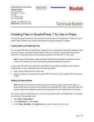
Platesetter Front View<br />
Front door<br />
Right side<br />
door<br />
Loading tray<br />
Figure 1: <strong>Lotem</strong> <strong>400</strong> platesetter (manual) front view<br />
Loading tray – for loading a plate into the platesetter.<br />
Front door – opening is controlled from PC Controller monitor.<br />
Right side door – access to electronic box and PC Controller.<br />
The <strong>Lotem</strong> <strong>400</strong> is now available with a multi cassette unit (MCU) for automated<br />
loading. For details see MCU for <strong>Lotem</strong> <strong>400</strong> <strong>Family</strong> User Guide, 653-00118A.
4 Chapter 1 – Introduction<br />
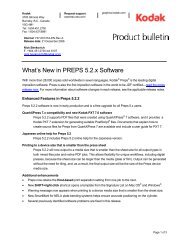
Platesetter Rear View<br />
Plate exit<br />
Rear door<br />
2 on/off<br />
pushbuttons<br />
Main circuit breaker<br />
Figure 2: <strong>Lotem</strong> <strong>400</strong> platesetter rear view<br />
Rear door – opening is controlled from PC Controller monitor.<br />
Plate exit – through which plates are unloaded after processing.<br />
On/Off pushbuttons – to power up and shut down the platesetter.<br />
Main circuit breaker – before you power on the platesetter, make sure main<br />
circuit breaker is on (set to 1). For total disconnection from the mains<br />
supply, set the main circuit breaker to 0.
Typical Customer Site Configuration 5<br />
Typical Customer Site Configuration<br />
A typical customer site configuration with the <strong>Lotem</strong> <strong>400</strong> platesetter is<br />
shown below.<br />
Plate room<br />
Workflow<br />
workstation<br />
PC controller<br />
monitor<br />
Conveyor<br />
<strong>Lotem</strong> <strong>400</strong><br />
Processor<br />
Figure 3: Typical configuration at customer site
6 Chapter 1 – Introduction<br />
The platesetter room may include:<br />
• <strong>Lotem</strong> <strong>400</strong> platesetter<br />
• PC Controller monitor; the user interface of the PC Controller that<br />
controls the platesetter operation.<br />
• Workflow workstation; jobs for the <strong>Lotem</strong> <strong>400</strong> platesetter are processed<br />
by the workstation.<br />
• Conveyor; moves the unloaded plates to the Processor.<br />
• Processor; option not supplied by Creo and intended for plates that<br />
need processing after expose.<br />
Note: The Plate stacker (for collecting unloaded plates) and Pre-heat oven (for<br />
plates that require heating), not supplied by Creo, are not shown in the figure.
Data and Communication Flow 7<br />
Data and Communication Flow<br />
Job data is sent from the workstation, which is connected to the PC<br />
Controller. The figure below shows the data and communication flow<br />
between the workstation and the platesetter.<br />
<strong>Lotem</strong> <strong>400</strong><br />
PC controller<br />
monitor<br />
Data cable (TSP)<br />
Point to point<br />
Workflow<br />
workstation<br />
Data from prepress<br />
Network TCP/IP<br />
100B/T<br />
Figure 4: Communication & data flow between platesetter & workstation
8 Chapter 1 – Introduction<br />
Turning the Platesetter On and Off<br />
To turn on the <strong>Lotem</strong> <strong>400</strong> platesetter:<br />
Important: When power is interrupted, the platesetter shuts down. To<br />
continue working when normal power returns, you must press either of<br />
the two yellow on/off pushbuttons twice (once to “turn off” the<br />
platesetter and once to turn it back on) as shown in Figure 2 on page 4.<br />
The pushbutton lights up and the platesetter restarts.<br />
Note: Turn on the platesetter before turning on the workflow workstation.<br />
1. Check the air pressure gauge (see figure below) in the air pressure unit.<br />
Make sure the air pressure is 6 ATM (88 psi).<br />
Figure 5: Air Pressure unit<br />
2. Make sure the main circuit breaker is on, that is, set to 1 (see Figure 2<br />
on page 4).<br />
3. On the rear panel, press the two (2) on/off pushbuttons so that they<br />
are both lit (see in Figure 2 on page 4).<br />
4. Press the on/off pushbutton on the PC Controller monitor.
Turning the Platesetter On and Off 9<br />
5. Double-click the <strong>Lotem</strong><strong>400</strong> icon on the PC desktop.<br />
6. Turn on the workflow workstation.<br />
To turn off the <strong>Lotem</strong> <strong>400</strong> platesetter:<br />
1. In the PC Controller software, click Routine Functions.<br />
2. From the Routine Functions menu, select Shut Down.<br />
3. In the Confirm message, click Shut Down.<br />
4. From the Start menu of your Windows, click Shutdown.<br />
5. When the message It is safe to turn off your computer<br />
appears, press the on/off pushbutton on the rear panel of the<br />
platesetter.
PC Controller User<br />
Interface<br />
Overview ..........................................................................................12<br />
User Interface ...................................................................................13<br />
Status Indicator.................................................................................14<br />
Operation Toolbar .............................................................................15<br />
Online Machine View........................................................................20
12 Chapter 2 – PC Controller User Interface<br />
Overview<br />
The PC Controller monitor is your interface with the <strong>Lotem</strong> <strong>400</strong><br />
platesetter; it monitors the platesetter operation, is constantly updated<br />
with the machine status and provides machine information. The<br />
platesetter is controlled by the PC Controller located inside the platesetter;<br />
the monitor resides on a nearby table, as shown in Figure 3 on page 5. The<br />
job data is sent from the workstation, that is connected to the PC<br />
Controller (see Figure 4 on page 7).<br />
Figure 6: PC Controller monitor
User Interface 13<br />
User Interface<br />
The PC Controller monitor is your basic working area, where the<br />
application indicators, buttons, popup menus and windows appear.<br />
The workflow-oriented platesetter user interface is intuitively designed,<br />
and minimal computer knowledge is required. The following features<br />
support this design:<br />
• Color-coded Status indicator indicates the machine status. For<br />
example, if a problem occurs while you are away from the monitor<br />
checking exposed plates, the problem indications on the screen are<br />
visible from a distance.<br />
• Large interface indicators can be seen from a distance, so you can be<br />
alerted even when working away from the monitor.<br />
• Monitor screen is divided into functional areas, as shown in the Main<br />
window figure below.<br />
Status indicator<br />
Operation toolbar<br />
Interlock<br />
indicator<br />
Message<br />
area<br />
Online machine view<br />
Figure 7: Main window areas
14 Chapter 2 – PC Controller User Interface<br />
Status Indicator<br />
The Status indicator is fairly large and color-coded for easy identification.<br />
The indicator updates you on machine status even when you are<br />
performing tasks away from the monitor. For example, you can easily see<br />
when the Status indicator changes to Attention.<br />
Start up (green) – machine is performing start up. All machine<br />
components go to Home position.<br />
Off-line (gray) – like Ready, but you cannot expose plates or run<br />
calibration tests; all other functions are available. After Start up and Stop,<br />
the machine automatically goes to Off-line. Click On-Line button on the<br />
Routine Functions menu to set machine to Ready.<br />
Ready (blue) – the machine is ready for operation and in On-Line mode;<br />
you may load a plate and begin the expose job.<br />
Working (green) – the machine is busy exposing the current job. While the<br />
machine is working, you can place another plate on the loading tray or<br />
send additional jobs from the workstation.<br />
Attention (red) – the machine has stopped working and requires your<br />
intervention, or has encountered a problem that requires servicing. A<br />
message appears in the message area and normal operation resumes only<br />
after the problem is solved.<br />
Service (purple) – a door is open or a panel was removed (the Interlock<br />
indicator appears on the Main window) or the machine is being serviced.<br />
If a door is open, the Online machine view shows the open door.
Operation Toolbar 15<br />
Operation Toolbar<br />
Routine Functions Menu<br />
The Operation toolbar to the right of the Status indicator is used to access<br />
all the operational options required when working with the platesetter PC<br />
Controller application. The Operation toolbar includes the Routine<br />
Functions, Utilities and Settings buttons used to open the relevant menus<br />
and the Stop button, as described below.<br />
Click the Routine Functions button to open the Routine Functions menu.<br />
The menu includes operations that are routinely performed by the user<br />
when working with the machine, as described below.<br />
Sub-menu option<br />
Description<br />
Open Front Door<br />
1. Click this button to open the front door.<br />
2. The door locking mechanism is released for 30 seconds. During<br />
these 30 seconds push the door slightly inward.<br />
3. The door releases. Lift the door to open it completely.<br />
When the front door is open, the safety interlocks are activated. As a<br />
result, machine systems such as drum motor and laser system do not<br />
operate. The machine is in Service mode (Status indicator is purple) and<br />
the Interlock indicator appears below the Status indicator with the name<br />
of the open door.<br />
Note: You can interactively open the door by clicking on the front door in the<br />
Online machine view<br />
Open Rear Door<br />
The rear door opening is similar to opening the front door.
16 Chapter 2 – PC Controller User Interface<br />
Sub-menu option<br />
Description<br />
Unload Plate<br />
This operation is available only when there is a plate on the drum and the<br />
machine is not working.<br />
In normal operation this option is not used since plate unloading is<br />
automatic. However, if the plate was not loaded properly or the expose<br />
process was not completed, you can manually initiate plate unloading.<br />
Click Unload Plate.<br />
Messages<br />
Click Messages to open the Message dialog box. When problems are<br />
encountered during machine operation, error messages are listed in the<br />
Message dialog box. The dialog box automatically opens whenever an<br />
error is recorded and the current error message is highlighted. All error<br />
messages recorded during the current run are listed.<br />
Note: To view the full message, double-click the vertical line in Description<br />
heading or manually resize the column.<br />
The Message dialog box has four buttons: Up/Down arrows for scrolling<br />
to previous/next messages; Reset to reset the machine after solving the<br />
problem that caused the error message (see Reset Machine); Help ? to<br />
launch the application online help system.<br />
Reset Machine<br />
Click this button when there is a need to reset the machine. For example,<br />
a problem that caused the machine to stop has been solved. The system<br />
prompts you to confirm the reset. The machine then resets to Ready,<br />
Off-line or Working status, depending on the status prior to the reset.<br />
Note: Reset machine on the Routine Functions menu is the same as the<br />
Reset button in the Message dialog box.
Operation Toolbar 17<br />
Sub-menu option<br />
Description<br />
On-line<br />
When the Status indicator is Off-line, you cannot expose plates.<br />
To expose plates, click On Line and wait until the machine resets to<br />
Ready.<br />
Shut Down<br />
Use this option for normal machine shutdown. See Turning the<br />
Platesetter On and Off on page 8.<br />
Utilities Menu<br />
Click the Utilities button to open the Utilities menu. The menu options are<br />
described below.<br />
Sub-menu option<br />
Description<br />
Expose Params<br />
The Expose Info window lists expose-related machine parameters. You<br />
may open this window anytime before or during exposure.<br />
Log Files<br />
Four windows open: Machine task list, two Log message windows (for<br />
service usage) and Expose queue list (data sent from the workstation).<br />
Machine Info<br />
PC Controller software version<br />
Hardware<br />
Lists the machine hardware parts<br />
Setup Tables<br />
The Plates Setup tables list the Intensity and Speed values for each plate.<br />
You can change the values. For example, in case of under exposure, you<br />
can increase intensity or speed for the resolution value in the expose.
18 Chapter 2 – PC Controller User Interface<br />
Sub-menu option<br />
Description<br />
Diagnostics<br />
Currently not supported.<br />
Remote Support<br />
When you click the Remote Support button, the following appears:<br />
Confirmation will allow the service engineer to work by remote with the<br />
user.<br />
Users<br />
Defines the type of user (some application settings and preferences are<br />
available only for service and R&D). Click Users to open the Define User<br />
dialog box, and choose user type – user, service or R&D. Then enter<br />
your password and click OK.
Operation Toolbar 19<br />
Settings Menu<br />
Click the Setting button to open the Settings sub-menu. The sub-menu<br />
options are described below.<br />
Sub-menu option<br />
Description<br />
Media Definitions<br />
Media definitions is used to define the type of plates you will be using.<br />
(the plate must be defined before it is loaded). This option is also used to<br />
edit the parameters of existing plates or to delete plates you will no<br />
longer use. For details see Media Definition on page 24.<br />
Preferences<br />
Preferences is used to define various settings. In the Preferences dialog<br />
box, you can set the following:<br />
Units – choose cm or inch to set units of measurement for all<br />
measurements, such as plate dimensions and thickness.<br />
Language – only English is implemented.<br />
Stop button<br />
The Stop button on Operation toolbar is used in case of an emergency<br />
stop. The drum and all the machine operations are immediately stopped,<br />
and the plate remains in its current position.
20 Chapter 2 – PC Controller User Interface<br />
Online Machine View<br />
The Online machine view shows the platesetter during operation; it<br />
enables you to see a simulation of machine operation. The main features<br />
are described below.<br />
Operational stage<br />
When the machine is in Working status, you can identify the current<br />
operational stage. You can see the plate loading onto the drum and the<br />
rotating drum. The remaining process time is indicated on the Progress<br />
indicator.<br />
Interlock indication<br />
When a door is open or a panel is removed, a safety interlock is activated.<br />
The Status indicator shows Service (purple) and the Interlock indicator<br />
appears below it with the name of the activated safety interlock. For<br />
example, a door is open, a panel is removed or a laser interlock is activated.<br />
For details on safety interlocks see <strong>Lotem</strong> <strong>400</strong> <strong>Family</strong> Safety Precautions for User,<br />
653-00275A.<br />
Figure 8: Main screen with Service status, interlock indicator and open doors
Online Machine View 21<br />
Attention<br />
When the machine status is Attention, the Online machine view may give<br />
some indication as to the cause of the problem. For example, if the plate is<br />
jammed inside the machine.<br />
Perform interactive operations<br />
You can open the front or rear door by clicking on the relevant door on the<br />
Online machine view. (This is the same as using Open Front door and<br />
Open Rear door on the Routine Functions menu.)<br />
Note: When you move the cursor on the door it becomes green. See figure<br />
below.<br />
Figure 9: Main screen with front door green when the cursor moves on it
Plate Handling<br />
Media Definition ...............................................................................24<br />
Loading Plates...................................................................................26<br />
Plate Geometry .................................................................................30
24 Chapter 3 – Plate Handling<br />
Media Definition<br />
You must define the type of plates you will use before loading them into the<br />
platesetter. This option is also used to edit the parameters of existing plates<br />
or delete plates you will no longer use.<br />
Click Media Definitions in the Settings menu to open the Media<br />
Definition window. Defined plate types are listed under Media list.<br />
Note: The plate names in the window are only examples. The platesetter<br />
supports plates of various specifications and various vendors, and Creo does not<br />
promote specific companies’ plates.<br />
Define new media:<br />
1. Click New.<br />
2. In the Name box, assign the media name. Recommended media name<br />
includes the manufacturer name.<br />
3. From the Manufacturer list box, select the manufacturer’s name.
Media Definition 25<br />
4. From the Type box, select Positive or Negative. This parameter is<br />
important for the Exposure type. For example, for a positive plate<br />
(that is, negative working plate), choose Positive and perform a<br />
negative exposure.<br />
5. In the Height box, type the height in millimeters. Maximum media<br />
height is 622 mm.<br />
6. In the Width box, type the width in millimeters. Maximum width is<br />
750 mm.<br />
7. In the Thickness box, type the media thickness as listed on the plate<br />
packaging. You must verify the media thickness with a micrometer.It<br />
should range: 0.15 – 0.3 mm.<br />
8. The Focus Value is automatically updated according to the media<br />
thickness you entered in step 7.<br />
9. In the Sensitivity box, type the value supplied by the plate vendor.<br />
This value is important for the initial adjustment of the optic system.<br />
10. In the Res/Int Table, select the value for your media.<br />
11. In the Res Mtr Table, select the Res Motor Table according to your<br />
media.<br />
12. Click Save to save the new media. The new plate name will then<br />
appear in the Media list.<br />
To modify the parameters of existing media:<br />
1. From the Media List, click the media whose parameters you want to<br />
modify. The selected media parameters appear in Media Parameters.<br />
2. Modify the parameters as explained in Define new media: on page 24.<br />
You can modify all media parameters, except the plate name (Name<br />
field is grayed).<br />
3. Click Save to save the new parameters.<br />
To delete a media set from the Media list:<br />
‣ From the Media List, click on the requested plate and click Delete.<br />
Note: To change the media name, you must first Delete the media. Then click<br />
New to configure it again.
26 Chapter 3 – Plate Handling<br />
Loading Plates<br />
Loading Plates via the Workstation<br />
The <strong>Lotem</strong> <strong>400</strong> platesetter has a semiautomatic plate loading process.<br />
When an expose job is initiated by the workstation the requested plate is<br />
placed at the center of the loading tray, emulsion side down. When the<br />
Loading plate pushbutton is pressed and the machine is ready to expose,<br />
the plate is automatically loaded into the platesetter.<br />
1. Define an Expose job on the workstation (see Brisque to <strong>Lotem</strong> <strong>Family</strong><br />
Connectivity User Guide, 399Z3R084A).<br />
2. A message is sent from the workstation to the PC Controller<br />
requesting that an appropriate plate be loaded in the platesetter. The<br />
message on the application Main window specifies the plate thickness<br />
and size.<br />
Figure 10: Message on PC Controller sent from workstation<br />
3. Get the requested plate.<br />
4. Place the plate on the loading tray (emulsion side down). Note the<br />
printed vertical scale on the tray; its numbers are plate width sizes.<br />
Make sure to align both sides of plate with the scale markers that<br />
correspond to plate width.
Loading Plates 27<br />
Plate on tray<br />
scale in<br />
inches<br />
scale in<br />
mm<br />
Loading<br />
plate<br />
pushbutton<br />
Figure 11: Loading plate tray<br />
Note: The location of the scale markers is such that the marker is visible on both<br />
sides of the plate when a plate that corresponds to that size is placed on tray. For<br />
example, when a plate that is 15 inches wide is placed correctly the 15 inch<br />
marker on each side is visible.<br />
5. Either click OK on the message (see figure 9) or press the Loading<br />
plate pushbutton to initiate plate loading (see figure 10).<br />
The figures on page 28 show a small and large plate on loading tray.<br />
When the machine is ready to expose, the plate is automatically loaded<br />
onto the drum.<br />
6. After the plate is loaded into platesetter, you can place another plate<br />
on the loading tray, ready for next expose job (if the plate size is<br />
known). The new plate is automatically loaded when the machine is<br />
Working status. If you did not place a new plate on the tray then a
28 Chapter 3 – Plate Handling<br />
message will appear when the machine is ready. Place the plate on the<br />
tray and press OK. A message appears after every separation<br />
requesting you to load the next plate.<br />
Figure 12: A small plate on loading tray<br />
Figure 13: A large plate on loading tray
Loading Plates 29<br />
Loading Plates Manually<br />
To manually load plates:<br />
1. Define the media on the PC Controller (see Media Definition on<br />
page 24).<br />
2. From the Utilities menu, select Hardware.<br />
3. Double-click Loading System.<br />
4. In the Media To Load list, choose the type of media you want to load.<br />
5. Get the plate you want to load.<br />
6. Place the plate on the loading tray (emulsion side down). Note the<br />
printed vertical scale on the tray; its numbers are plate width sizes.<br />
Make sure to align both sides of plate with the scale markers that<br />
correspond to plate width.<br />
7. Push the plate inwards until both edges reach the loading stopper<br />
door inside the platesetter.<br />
8. In the Loading System dialog box, click Load. Make sure Media on<br />
Drum is None. The plate is loaded.<br />
Figure 14: Loading system window
30 Chapter 3 – Plate Handling<br />
Plate Geometry<br />
This section describes aspects of the plate geometry and image area. These<br />
aspects will help you plan for the plate exposure process and define correct<br />
settings for your press and plate, and your image offset.<br />
The figure below shows a negative working plate, where two strips of<br />
emulsion remain – 10 mm at the head margin and 6 mm at the tail margin.<br />
head margin<br />
min 10 mm<br />
max. plate size = 750 x 622<br />
622 mm<br />
max image area = 750 x 606<br />
606 mm<br />
tail margin<br />
min 6 mm<br />
750 mm<br />
head margin<br />
head gripper<br />
Figure 15: Negative working plate – various plate dimensions<br />
Head margin – defined on the workstation, as one of the press format<br />
parameters. It defines the distance from the plate edge until the beginning<br />
of the layout or the exposed image. This parameter is also known as leading<br />
edge to print.<br />
Tail margin – defined on the workstation as one of the press format<br />
parameters. It defines the distance from the back edge of the plate to the<br />
edge of the file or layout.<br />
H (height) – plate height (around the drum).<br />
W (width) – plate width (along the drum width).
Plate Geometry 31<br />
In a negative exposure of a positive working plate, there is always an<br />
emulsion area on the plate that is not exposed, therefore emulsion areas<br />
remain. The size of these areas is determined as follows:<br />
• At the head, the area is equal to the width of the plate and at a height of<br />
up to 10 mm.<br />
• At the tail, the area is equal to the width of the plate and at a height of<br />
up to 6 mm.<br />
The image alignment is determined by the Alignment, as defined in the<br />
Plate Expose window on the workstation. For details, see the Brisque to<br />
<strong>Lotem</strong> <strong>Family</strong> Connectivity User Guide, 399Z3R084.
User Troubleshooting<br />
Generic Troubleshooting Questions ...................................................34<br />
Startup Problems...............................................................................35<br />
Calling Response Center For Support ................................................36<br />
Plate Loading Failure .........................................................................37<br />
Plate Unloading Problems..................................................................49<br />
Exposure Failure Problem ..................................................................51<br />
Communication Problems with TSP Board .........................................52
34 Chapter 4 – User Troubleshooting<br />
Generic Troubleshooting Questions<br />
There are several troubleshooting steps that you should complete before<br />
calling the Response Center. These steps can prevent extensive down-time<br />
by enabling you to solve problems independently. You will find these steps<br />
are fully explained in the relevant troubleshooting document. Ideally, the<br />
customer will have completed these steps before calling the Response<br />
Center, and also reviewed the following questions and written the answers<br />
down. If after completing these steps you find that the problem is not<br />
resolved, please answer the following questions before calling the Response<br />
Center. Write down your answers and have them available during your call.<br />
The questions are as follows:<br />
• When was the last time the machine worked properly?<br />
• What was done since then? For example:<br />
<br />
<br />
<br />
Was the machine moved?<br />
Was the machine cleaned?<br />
Was a new batch or type of plates used?<br />
• Was an error message displayed on screen? If yes, what did it say<br />
(include numbers, if any).<br />
• What is the software version?<br />
• Does the problem happen all the time (with all plates), or just some of<br />
the time? For example:<br />
<br />
<br />
With a particular plate brand, type and/or size?<br />
Only when a few plates are left in the cassette?<br />
• Does the problem seem to be a random occurrence?<br />
• What are the temperature and humidity levels in the plate storage<br />
room? For example:<br />
Do they adhere to the plate manufacture’s guidelines? If not:<br />
• In what ways?<br />
• Does the temperature fluctuate radically?
Startup Problems 35<br />
Startup Problems<br />
PC Does Not Boot<br />
Following are the most common start up problems:<br />
• PC does not boot<br />
• Windows does not start<br />
• Windows does not launch<br />
• <strong>Lotem</strong> application aborts<br />
1. Verify that all power circuit breakers are in the ON position.<br />
2. Verify that both on/off buttons at the rear of the platesetter (yellow<br />
pushbuttons) are in the out position and lit.<br />
3. Verify that the PC monitor power is ON.<br />
Windows Does Not Launch<br />
Windows does not launch and the error message relates to missing or<br />
corrupted files.<br />
1. Continue the startup and follow the screen instructions. Wait until the<br />
Windows startup is complete. Then perform Windows shutdown and<br />
reboot the PC.<br />
2. If the startup fails and the PC hangs:<br />
• Press F1 during initial startup and choose Safe Boot.<br />
• Run a system check/test from AccessoriesDisk/ToolScan/Disk.<br />
3. In some cases, Scan Disk will not resolve the problem. In such cases,<br />
you may need to reload the following files onto your hard disk: first<br />
Windows, then drivers, and finally the <strong>Lotem</strong> application. Please<br />
contact your service representative for details before you proceed.
36 Chapter 4 – User Troubleshooting<br />
Windows Does Not Start<br />
When Windows does not start and the error message relates to boot disk/<br />
diskette:<br />
1. Open the rear door by inserting a long screwdriver into the holes (on<br />
both left and right sides).<br />
2. Open the right side door and make sure that a diskette was not left<br />
inside the diskette drive.<br />
Calling Response Center For Support<br />
Whenever you need to call Creo service representative for help, the<br />
following information should be supplied. This information is important<br />
for addressing your problem.<br />
• In case of an error in the PC Controller application, write down the<br />
first five (5) error messages that are listed in the Message window of the<br />
PC Controller main window.<br />
• In case of error in the Brisque application, write down the Brisque<br />
error number and message.<br />
• In case of loading/unloading failure, write down the plate location, if<br />
known.<br />
• Write down the Brisque Job information (Job type, number of<br />
separations, Screen set that is used and LW/CT resolution).
Plate Loading Failure 37<br />
Plate Loading Failure<br />
Releasing Stuck Plates<br />
CAUTION: When handling the plates, especially if you need to release them,<br />
be sure to wear protective gloves as the plate edges are sharp.<br />
The following are the most common plate loading failures:<br />
• Plate is stuck<br />
• Double Loading<br />
• Drum related errors<br />
• Punch is stuck<br />
The following are the most common error messages:<br />
• Error Message: Plate did not reach punch position<br />
• Error Message: Vacuum didn't grab plate<br />
• Error Message: Drum Fly-off<br />
• Error Message: Illegal plate size<br />
• Error Message: Illegal gripper width<br />
The following sections describe the actions that you should take when the<br />
above failures occur.<br />
Plates may get jammed inside the platesetter during plate loading. As<br />
explained in Loading Plates Manually on page 29, the message sent from<br />
the workstation to the PC Controller requests you to load a plate of<br />
specified size and thickness. If you load a plate with an incorrect height<br />
value, the plate will get jammed and cannot be properly loaded onto the<br />
drum. In this case, you will need to manually remove the jammed plate.<br />
Special precautions are required when performing this procedure.<br />
Note: Before removing a plate, remove objects or clothing that might get caught<br />
in the revolving drum or other moving parts, such as, ties and jewelry. Fold long<br />
sleeves and gather long hair.<br />
Note: Before removing a plate, switch off the main drum power switch on the<br />
Distribution box.
38 Chapter 4 – User Troubleshooting<br />
Note: The plate edges are sharp so the plate should not be handled with bare<br />
hands. Wear gloves before attempting to release the plate.<br />
Note: It is recommended to release the entire plate as one piece; do not<br />
attempt to cut the plate.<br />
Note: Released plates must be disposed; you may not re-use the plate.<br />
Note: Plate remnants left in the platesetter may cause mechanical and laser<br />
radiation hazards!<br />
When plate loading fails because of incorrect plate size, the Status<br />
indicator is Attention and the message window opens with the message<br />
“Illegal plate size”.<br />
To manually release the stuck plate:<br />
1. You first need to open the upper door from the main window: to<br />
interactively open the door, click on the rear door on the Machine<br />
online view. Alternatively, click Open Rear Door from Routine<br />
Functions menu.<br />
2. When the rear door is open, stand at the rear side of the platesetter<br />
and rotate the drum forward, towards the front of the platesetter.<br />
3. Rotate the drum until you can see the detached edge of the plate, that<br />
is, the edge that is not held by the tail grippers.<br />
4. Hold the detached edge of plate and gently pull it towards you until<br />
you can see the other edge of the plate, that is, the edge that is held by<br />
the head grippers.<br />
5. To release the plate from the head grippers: hold both sides of plate<br />
(left and right) and pull the plate abruptly towards you.
Plate Loading Failure 39<br />
6. Verify that the tail gripper did not move. If it did, then move it to the<br />
Preload position (0). To do this,<br />
a. Drag the tail gripper to the preload position (as shown in the<br />
picture below).<br />
b. In the Hardware dialog box, open the Loading system directory.
40 Chapter 4 – User Troubleshooting<br />
c. Double-click Loading system.<br />
d. In the Loading System dialog box, click Restart Plate State.<br />
e. Click Drum Init.<br />
f. Click Pre-load (in the same dialog box) to move the tail gripper to<br />
the correct position according to the defined plate size.<br />
The status indicator shows Ready (blue).<br />
7. Close the rear door.<br />
8. Close the loading system and hardware windows.<br />
9. Click the Reset button in the message window, and then Reset in the<br />
Confirm message that appears.<br />
Machine status is now Ready and you can proceed to loading the correct<br />
plate size.
Plate Loading Failure 41<br />
Double Loading<br />
Tip: Open the front door and look into the loading area in order to find out<br />
whether double loading has occurred.<br />
1. If the plates are in the cassette to punch area:<br />
• Gently try to push them back into the cassette.<br />
• If this is not possible, open the upper cover, remove the plates and<br />
place paper in between them and then place the plates back into<br />
the cassette.<br />
• In the Hardware window, select Loading System/Loading System<br />
to open the Loading System window.<br />
• In the window, click Restart Plate State.<br />
2. If plates are stuck halfway on the drum:<br />
• Open the rear door.<br />
• Then using your hands, slowly rotate the drum away from you<br />
(towards the cassette) until you can see the plate tail edge. (A<br />
metallic noise might be heard, which is caused by the edge being<br />
dragged on the roller system.)
42 Chapter 4 – User Troubleshooting<br />
3. If the plates are held by a tail gripper(s):<br />
Figure 16: Tail gripper<br />
• Release the gripper(s) from the plate.<br />
• Hold the edges of both plates and pull the plates towards you until<br />
the head gripper is visible.<br />
• Then, press on one or two head grippers while pulling the plates<br />
abruptly.<br />
• Completely remove the plates from the drum.<br />
• In the Hardware window, select Loading System/Loading System<br />
to open the Loading System window.<br />
• In the window, click Restart Plate State.<br />
• Move the gripper to Preload position (see Plate Geometry on<br />
page 30). Open the loading system and define a plate and press<br />
pre-load.<br />
4. Occasionally, a batch of plates may be problematic and a source for<br />
excessive static electricity. This may cause plate-loading problems.<br />
Tip: To minimize the probability of double loading, make sure the room<br />
temperature is maintained between 21 to 25 degrees, and humidity is<br />
approximately 55%.
Plate Loading Failure 43<br />
Punch is Stuck<br />
If the punch gets stuck while punching a plate, try the following:<br />
Figure 17: Punch system<br />
1. Remove the plate. If you cannot remove it, the punch pin may still be<br />
in its low position in the plate.
44 Chapter 4 – User Troubleshooting<br />
2. If this is the case, you need to release the punch:<br />
<br />
<br />
<br />
<br />
Make sure the doors are closed.<br />
In the Hardware window, select Punch System/Punch Motor/Punch<br />
Motor xx (where xx is the punch number) and Punch System/<br />
Detector/Punch Motor #Home Pos.Det.<br />
The punch numbers proceed from left to right.<br />
If you are not sure which punch needs to be released, open the front<br />
door and remove the plate and close the door. Then activate the<br />
punches one by one by clicking Start, to see which is the<br />
problematic punch. If the Home Position does not change to ON,<br />
then that is the problematic punch.<br />
If the plate is stuck and you cannot remove it, then activate the<br />
punches one by one by clicking Start, to see which is the<br />
problematic punch. If the Home Position does not change to ON,<br />
then that is the problematic punch.<br />
If you discover a problematic punch, contact your service representative.<br />
Drum Related Errors<br />
Plate loading fails with drum related error Drum did not reach<br />
position or Load Gripper is protected by Load Gripper<br />
Protector. There may be several causes to this error message. Check the<br />
following possibilities:<br />
1. Verify that all covers and panels are properly closed. Make sure that no<br />
interlock is active (that is, an interlock indicator does not appear on<br />
the main application window, and the machine status is not Service).<br />
2. Verify that the air compressor supply to the platesetter is adequate<br />
(minimum setting of the air compressor should be 6 Bar).<br />
3. From the Hardware window, select Loading System/Loading System.<br />
In the Loading System dialog box, click Drum Init.
Plate Loading Failure 45<br />
Error Message: Plate Did Not Reach Punch Position<br />
Plate loading fails with error message: Plate did not reach punch<br />
position.<br />
1. Verify that the plates are properly centered in the cassette (both side<br />
brackets touch the plate sides) and the rear bracket is approximately<br />
1 mm from plate edge.<br />
2. Check if the plate edge is bent, cut or coated with glue. This may cause<br />
the short pins to fail a plate reading when the pins are supposed to<br />
touch the plate (these are the centering system pins and/or the pins<br />
near the punch blocks). Try rotating the plate 180 degrees. This may<br />
help to verify if the plate edge is the cause of the problem.<br />
3. Look through the cassette entrance towards the punch block units.<br />
4. If you can see a punch pin in the middle of the punch slot, this means<br />
that a plate may get stuck on its way to the punch. In this case, contact<br />
your service representative.<br />
punch slot<br />
Figure 18: Punch
46 Chapter 4 – User Troubleshooting<br />
Error Message: Vacuum Did Not Grab Plate<br />
Plate loading fails with error message Vacuum did not grab plate.<br />
Open the front door and check the plate location. The cause and solution<br />
to this problem depends on plate location:<br />
1. Verify that the air compressor supply to the platesetter is adequate<br />
(minimum setting of the air compressor should be 6 Bar).<br />
2. Open the cassette door. If you can see the plate inside the cassette,<br />
verify that the plate edge is not under the two side brackets. In this<br />
case, the plate cannot be loaded. Try to reposition the plate in the<br />
cassette or add more plates into the cassette.<br />
Figure 19: Centering system<br />
3. Verify that the loading bar is horizontal to the plate (see below). Push<br />
the bar toward the drum until it touches the two vertical metal<br />
brackets. The loading bar should be parallel to the brackets on both<br />
axes. If it is not parallel, contact your service representative.
Plate Loading Failure 47<br />
Figure 20: XY Bar<br />
4. If the plate is partially out of the cassette, check that all the Vacuum<br />
suction cups on the XY bar are intact, complete and are not torn. If<br />
there is a problem with the suction cups, contact your service<br />
representative.<br />
5. If the plate is halfway onto the punch blocks, examine the front edge<br />
of the plate. If there are bends or dents in the plate, these may be as a<br />
result of the plate hitting one of the punch blocks as it is loaded from<br />
the cassette. Remove the plate and rotate it in the cassette.<br />
Error Message: Drum Fly-off<br />
1. Open the rear door, and manually remove the plate.<br />
2. Move all tail grippers to the end of their slots (near the head grippers).<br />
Make sure that the tail grippers are not moved beyond the head<br />
gripper holes.<br />
3. Verify that the load/unload rollers are in their proper position (they<br />
did not separate from the springs).<br />
4. Close the doors.<br />
5. From the Hardware window, select Loading System/Loading System,<br />
and click the following: Restart Plate State, Drum and New Plate.
48 Chapter 4 – User Troubleshooting<br />
6. Resend the job from the Brisque.<br />
Error Message: Illegal Plate Size<br />
Error Message: Illegal Gripper Width<br />
There may be several causes to this error message. Do the following:<br />
• Measure the plate in the cassette.<br />
• Verify that the plate size defined in the Off-line/Current Cassette dialog<br />
box is the plate size that was actually loaded into the cassette. Plate size<br />
should be within +/-1 mm of the dimensions defined in the Media<br />
Definition dialog box.<br />
• Clean the centering pins.<br />
• Check the plate edges where the centering pins touch, see if there are<br />
bumps, dents, dirt, glue etc... - this could prevent any electrical contact<br />
from occurring.<br />
There may be several causes to this error message. Check the following<br />
possibilities:<br />
1. Make sure no paper accompanied the plate to the centering system.<br />
2. Open the front door and manually remove the plate from the drum.<br />
For instructions, see Releasing Stuck Plates on page 37.<br />
3. Move all tail grippers to the end of their slots (near the head gripper).<br />
Make sure not to move them beyond the head gripper holes.<br />
4. Close the front door.<br />
5. From the Hardware window, select Loading System/Loading System.<br />
6. In the Loading System window that is displayed, click New Plate.<br />
7. Clean the two red LED sensors located on both sides of the drum<br />
chassis using a dry cloth (see below).
Plate Unloading Problems 49<br />
Figure 21: Side to side detector<br />
Plate Unloading Problems<br />
Plate Does Not Unload<br />
Plate unloading problems may be caused by one of the following:<br />
• Plate does not unload from the platesetter<br />
• Unload failure after plate restart<br />
1. Make sure that the previous plate entered the processor correctly.<br />
2. If it did not, this plate may be blocking the conveyor sensor. Verify<br />
that the processor is in Ready state, and clear any error message on the<br />
processor panel.<br />
3. If there is still a problem, contact the processor technician.<br />
4. Move the previous plate into the processor. Then, from the Routine<br />
Functions menu, click Unload Plate to manually unload the current<br />
plate.<br />
5. Check that there are no error messages relating to Vibration or Fly<br />
Off. If there are such messages, please contact your service<br />
representative.
50 Chapter 4 – User Troubleshooting<br />
6. Try to manually unload the plate. Then load and unload a different<br />
plate size. If this goes smoothly then there may be a specific problem<br />
with the original plate size.<br />
Figure 22: Unloading system<br />
7. Load the plate into the processor. Then examine the plate to see if it<br />
was partially exposed, or not exposed at all. If it was partially exposed,<br />
this can indicate a problem with the exposure sequence and not a<br />
plate-unloading problem.
Exposure Failure Problem 51<br />
Unload Failure After Plate Restart<br />
If you have a problem performing Restart Plate State while there is a plate<br />
on the drum, then you will not be able to expose the plate or unload it,<br />
because Restart Plate State resets the plate status to No plate on drum. To<br />
resolve this problem, click Force Plate On Drum to force the system to<br />
acknowledge the plate on the drum. Then, you can either expose the plate<br />
or unload it.<br />
Important: Never use Force Plate On Drum before performing a visual<br />
check that there is actually a plate on the drum.<br />
Exposure Failure Problem<br />
Exposure Does Not Start<br />
Exposure does not start at all and the error messages relates to the Host.<br />
There may be several causes to this error message.<br />
1. Verify the machine is ON and in Ready mode.<br />
Note: Make sure there is no error message on the PC Controller.<br />
2. On Brisque, go to Devices > Platesetter; select <strong>Lotem</strong> > <strong>Lotem</strong> <strong>400</strong>.<br />
3. Click the Reconfigure button.<br />
4. In the Queue Manager, a red blinking icon appears on the upper part<br />
of the dialog box indicating an error. From the Tools menu, select<br />
Operate Control > Plate Expose > <strong>Lotem</strong> <strong>400</strong>.<br />
5. Click OK.<br />
If the blinking icon disappears, then send another expose job. If not, in<br />
the In Queue area, select the problematic error message. Double-click<br />
it to receive an explanation of the problem.
52 Chapter 4 – User Troubleshooting<br />
Communication Problems with TSP Board<br />
1. Verify that the Data cable is securely connected to the workstation.<br />
2. Check that the Network or the Point-to-Point cable between the<br />
platesetter and the workstation is properly connected.<br />
3. Check if you can ping the platesetter from the workstation:<br />
• Open the terminal window on the workstation<br />
• On the PC, open Settings/Control Panel/Network/TCPIPP/<br />
Properties and type ping 192.9.200.2.<br />
To stop the ping sequence type: CTRL+C.
Index<br />
A<br />
Active interlock name, 20<br />
Air pressure unit<br />
gauge, 8<br />
Attention status, 14, 21<br />
Automatic plate loading, 27<br />
B<br />
Brisque, 26<br />
Brisque Impose, 2<br />
C<br />
Conveyor, 6<br />
Customer site configuration, 5<br />
D<br />
Data & communication flow, 7<br />
Define user dialog box, 18<br />
Defining new plates, 24<br />
Deleting plates, 25<br />
E<br />
Emergency stop, 19<br />
Emulsion area, 31<br />
Error messages, 16<br />
Expose Info window, 17<br />
Expose queue list, 17<br />
Exposed image area, 30<br />
F<br />
Front door, 3<br />
H<br />
Head grippers, 38<br />
Head margin, 30<br />
See also Margins<br />
I<br />
Incorrect plate size, 38<br />
Interactive operations, 21<br />
Interlock indication, 20<br />
Interlock indicator, 14<br />
J<br />
Jammed plate<br />
precautions, 37<br />
releasing, 37<br />
L<br />
Language, 19<br />
Leading edge to print, 30<br />
Loading plate on tray, 26, 29<br />
Loading plate pushbutton, 26<br />
Loading Plates<br />
manually, 29<br />
via workstation, 26<br />
Loading tray, 3, 26<br />
markers, 26, 29<br />
Log Files, 17<br />
Log message window, 17<br />
<strong>Lotem</strong> <strong>400</strong><br />
Front End, 2<br />
front view, 3<br />
plate size, 2<br />
power up, 8<br />
product overview, 2<br />
rear view, 4<br />
shutdown, 9<br />
<strong>Lotem</strong> <strong>400</strong> with MCU, 2<br />
M<br />
Machine parameters, 17<br />
Machine reset, 16<br />
Machine simulation, 20<br />
Machine status, 14<br />
Machine task list, 17<br />
Main circuit breaker, 4<br />
Main window, 13<br />
active (green) door, 21<br />
Manual drum rotatation, 38<br />
Manual plate unloading, 16<br />
Manually loading plats, 29<br />
Message dialog box, 16<br />
Messages, 16<br />
N<br />
Negative plate, 25<br />
Negative working plate, example, 30<br />
O<br />
Off-line status, 14, 17<br />
On/Off pushbuttons, 4<br />
Online help, 16<br />
Online machine view, 20<br />
Open front door<br />
interactively, 21<br />
Open rear door<br />
interactively, 21<br />
Operation menu, 15<br />
P<br />
PC Controller<br />
user interface, 13<br />
PC Controller monitor, 6, 12<br />
Plate automatic loading, 27<br />
Plate exit, 4<br />
Plate Expose on Brisque, 31<br />
Plate geometry, 30<br />
Plate height, 30<br />
Plate stacker, 6<br />
Plate width, 30<br />
Plates<br />
defining, 24<br />
deleting, 25<br />
existing names, 24<br />
loading, 37<br />
manufacturer, 24<br />
placing on loading tray, 26, 29<br />
positive/negative, 25<br />
release jammed plate, 37<br />
sensitivity, 25<br />
thickness, 25<br />
unloading, 49<br />
Platesetter<br />
online view, 20<br />
shutdown, 9<br />
Positive plate, 25<br />
Preferences, 19<br />
Pre-heat oven, 6
54 <strong>Lotem</strong> <strong>400</strong> <strong>Family</strong> User Guide<br />
Press Formats<br />
on PC controller, 30<br />
Problems, 49<br />
Process time indication, 20<br />
Processor, 6<br />
Progress indicator, 20<br />
R<br />
Ready status, 14<br />
Rear door, 4<br />
Res. Int. Table, 25<br />
Reset button, 40<br />
Reset machine, 16<br />
Right side door, 3<br />
Routine Functions, 15<br />
S<br />
Safety interlocks, 20<br />
Save Plate, 25<br />
Scale markers, plate, 26, 29<br />
Sensitivity, 25<br />
Service mode, 15<br />
Service status, 14, 20<br />
Setting, 19<br />
Start up status, 14<br />
Status indicator, 14<br />
Stop button, 19<br />
T<br />
Tail grippers, 38<br />
Tail margin, 30<br />
See also Margins<br />
U<br />
Units of measurement, 19<br />
User interface<br />
features, 13<br />
main window, 13<br />
User types, 18<br />
Utilities, 17<br />
W<br />
Working status, 14