
You also want an ePaper? Increase the reach of your titles
YUMPU automatically turns print PDFs into web optimized ePapers that Google loves.
Networking<br />
Parallel processing<br />
Computer to plate<br />
<strong>EverSmart</strong> <strong>Jazz</strong><br />
Reliable proofing<br />
Workflow<br />
Stochastic screening<br />
Digital printing<br />
Stochastic screening<br />
User Guide - Mac Platform<br />
English<br />
Version<br />
High volume film out<br />
Parallel proc<br />
Plate ready<br />
Catalog No.<br />
399Z52678A
IMPORTANT NOTICE<br />
This document is delivered subject to the following conditions and restrictions:<br />
This document contains proprietary information of Scitex<br />
Corporation Ltd.<br />
Such information is hereby supplied solely for the purpose<br />
of assisting authorized users of Scitex products.<br />
Without the express prior written permission of Scitex, no part of<br />
the contents hereof may be used for any other purpose, disclosed<br />
to any person or firm, or reproduced by any means.<br />
The text and drawings herein are for the purposes of illustration<br />
and reference only. The specifications on which they are based are<br />
subject to change without notice.<br />
Catalog No. 399Z52678A<br />
Copyright © 1997 by<br />
Scitex Corporation Ltd.<br />
All Rights Reserved<br />
First edition: May 1999 (SW version 2.0.0)<br />
Important Notice
Trademarks<br />
Scitex, the Scitex logo, <strong>EverSmart</strong>, <strong>EverSmart</strong> Pro, <strong>EverSmart</strong><br />
Supreme, <strong>EverSmart</strong> DOT ® , <strong>EverSmart</strong> <strong>Jazz</strong>, <strong>EverSmart</strong> <strong>Jazz</strong>+,<br />
Dolev, Max DR, XY Stitch, ResoLUT PS (PS/W), Scitex Remake,<br />
Spontane, Whisper, Scitex LW, Scitex NLW, Scitex CT, Scitex<br />
PSImage, Scitex APR, Scitex Remake and Brisque are trademarks<br />
of Scitex Corporation Ltd. or its wholly-owned subsidiaries and<br />
may be registered in certain jurisdictions.<br />
PostScript® and Adobe PhotoShop® are trademarks of Adobe<br />
Systems, Incorporated, are registered in the U.S. Patent and<br />
Trademark Office and may be registered in other jurisdictions,<br />
as well.<br />
QuarkXPress is a registered patent and trademark of Quark, Inc.<br />
Apple, ColorSync and Power Macintosh are registered trademarks<br />
Apple Computer, Inc.<br />
All other company or product names are the trademarks or<br />
registered trademarks of their respective holders.<br />
US Patents<br />
This product is covered by one or more of the following US patents:<br />
4.350.996 4.365.256 4.456.924 4.500.919 4.834.520 4.853.709<br />
4.897.737 4.931.637 4.992.862 5.079.721 5.103.407 5.111.308<br />
5.113.249 5.119.440 5.122.871 5.124.547 5.150.225 5.153.769<br />
5.155.782 5.157.516 5.200.816 5.208.888 5.221.997 5.227.895<br />
5.247.174 5.247.352 5.283.140 5.285.297 5.296.935 5.299.020<br />
5.313.278 5.323.248 5.325.217 5.328.032 5.331.439 5.333.064<br />
5.339.176 5.343.059 5.355.446 5.359.458 5.367.388 5.384.648<br />
5.384.899 5.412.491 5.412.737 5.420.702 5.473.733 5.481.379<br />
5.488.906 5.497.252 5.508.828 5.509.561 5.519.792 5.519.852<br />
5.526.107 5.526.143 5.532.728 5.561.691 5.568.595 5.576.754<br />
5.579.115 5.592.309 5.594.556 5.600.448 5.608.822 5.615.282<br />
5.623.001 5.636.330 5.649.220 5.650.076 5.652.804 5.691.823<br />
5.691.828 5.696.393 5.699.174 5.708.736 5.739.819 5.742.743<br />
5.764.381 5.813.346<br />
<strong>EverSmart</strong> <strong>Jazz</strong> User Guide - Mac Platform
ABOUT THIS MANUAL<br />
This manual is a complete guide to the operation of the <strong>EverSmart</strong><br />
<strong>Jazz</strong> scanners. The application described in this manual applies to<br />
software version 2.0.0.<br />
The <strong>EverSmart</strong> scanners are supplied with the <strong>EverSmart</strong> scanning<br />
software that includes the Scitex automation and image manipulation<br />
features. An optional software upgrade, <strong>EverSmart</strong> Expert<br />
scanning application, that offers the user enhanced tools for full<br />
control over image quality is available.<br />
The user guide contains the following chapters:<br />
• 1-Introduction is an overview of the <strong>EverSmart</strong> <strong>Jazz</strong> and the<br />
main operational features.<br />
• 2-Preparation describes preparing and mounting originals in<br />
the scanner, and the power up/shutdown process.<br />
• 3-Tools & Palettes describes the user interface, including tools<br />
for controlling the foreground/background operations, and<br />
tools for defining and editing an image.<br />
• 4-Basic Scan describes the basic CMYK scan procedure for color<br />
transparencies, including: setup and preview options, and<br />
performing final scan.<br />
• 5-Tone Reproduction, includes End Points, for defining the<br />
effective density range and removing color cast, and Gradation,<br />
for further tonal adjustment and color balance.<br />
• 6-Color, describes the color functions. Color Correction for<br />
HSL/CMYK Selective and Global changes; Gray Control to<br />
modify the grays; Input Gray Levels to modify the RGB input<br />
values, and the Separation setup functions.<br />
• 7-Sharpness, describes the Sharpness function, editing the<br />
Sharpness controls and performing max detail prescan.<br />
About this Manual
• 8-Special Workflows, describes the scan procedures used for<br />
special purposes and for originals other than color transparency.<br />
For example, negatives, line-art, RGB scan and ICC flow.<br />
• 9-Setup, describes setup options and operation mode<br />
preferences, such as tone reproduction, densitometer and final<br />
file formats.<br />
Document Conventions<br />
The Image Correction Examples booklet (Catalog No. 399Z50389A)<br />
illustrates the main functionality of the application in full color<br />
images. Throughout this user guide, specific references are given<br />
to relevant images in the booklet.<br />
References<br />
User Interface<br />
Elements<br />
Software Functions<br />
and Buttons<br />
➤ followed by text<br />
References to other sections of this<br />
document or to other documents are set<br />
in italic type. For example: Refer to<br />
Chapter 4, Basic Scan.<br />
Dialog boxes and other named user<br />
interface elements are set in italic type.<br />
For example: Setup menu.<br />
Named commands and buttons that you<br />
activate are set in bold type. For example:<br />
From the Setup menu, choose Gray<br />
Control.<br />
An action you perform.<br />
• followed by text Listed item.<br />
✎ followed by text A note for your attention.<br />
✔ followed by text A recommended operational tip you can<br />
use.<br />
! followed by text Reference to relevant color example in the<br />
Image Correction Examples booklet<br />
(Catalog No. 399Z50389A).<br />
Document Conventions
TABLE OF CONTENTS<br />
ABOUT THIS MANUAL<br />
1. INTRODUCTION<br />
Overview . . . . . . . . . . . . . . . . . . . . . . . . . . . . . . . . . . . . . . . . . . . 1.1<br />
Front View . . . . . . . . . . . . . . . . . . . . . . . . . . . . . . . . . . . . . . . . . . 1.3<br />
Operational Features . . . . . . . . . . . . . . . . . . . . . . . . . . . . . . . . . . 1.3<br />
2. PREPARATION<br />
Operating Panel . . . . . . . . . . . . . . . . . . . . . . . . . . . . . . . . . . . . . . 2.1<br />
Power Up/Shutdown . . . . . . . . . . . . . . . . . . . . . . . . . . . . . . . . . 2.2<br />
Mounting Originals . . . . . . . . . . . . . . . . . . . . . . . . . . . . . . . . . . . 2.3<br />
Direct Mount . . . . . . . . . . . . . . . . . . . . . . . . . . . . . . . . . . . . . . . . 2.3<br />
User Defined Mask . . . . . . . . . . . . . . . . . . . . . . . . . . . . . . . . . . . 2.4<br />
Slide Holder . . . . . . . . . . . . . . . . . . . . . . . . . . . . . . . . . . . . . . . . . 2.9<br />
3. TOOLS & PALETTES<br />
Overview . . . . . . . . . . . . . . . . . . . . . . . . . . . . . . . . . . . . . . . . . . . 3.1<br />
Preview Browser . . . . . . . . . . . . . . . . . . . . . . . . . . . . . . . . . . . . . 3.3<br />
Scan Palette . . . . . . . . . . . . . . . . . . . . . . . . . . . . . . . . . . . . . . . . . 3.6<br />
Queue Window . . . . . . . . . . . . . . . . . . . . . . . . . . . . . . . . . . . . . . 3.7<br />
Windows Palette . . . . . . . . . . . . . . . . . . . . . . . . . . . . . . . . . . . . . 3.9<br />
Image Display Window . . . . . . . . . . . . . . . . . . . . . . . . . . . . . . . 3.10<br />
Display Area . . . . . . . . . . . . . . . . . . . . . . . . . . . . . . . . . . . . . . . . . 3.11<br />
Tools & Display Option . . . . . . . . . . . . . . . . . . . . . . . . . . . . . . . . 3.12<br />
Image Palette . . . . . . . . . . . . . . . . . . . . . . . . . . . . . . . . . . . . . . . . 3.19<br />
Keyboard Controls . . . . . . . . . . . . . . . . . . . . . . . . . . . . . . . . . . . . 3.20<br />
Keyboard Shortcuts . . . . . . . . . . . . . . . . . . . . . . . . . . . . . . . . . . . 3.22<br />
4. BASIC SCAN<br />
Entering Application . . . . . . . . . . . . . . . . . . . . . . . . . . . . . . . . . . 4.1<br />
Setup Mode . . . . . . . . . . . . . . . . . . . . . . . . . . . . . . . . . . . . . . . . . 4.2<br />
Layout Display . . . . . . . . . . . . . . . . . . . . . . . . . . . . . . . . . . . . . . . 4.9<br />
Performing Preview . . . . . . . . . . . . . . . . . . . . . . . . . . . . . . . . . . . 4.12<br />
Preview Mode . . . . . . . . . . . . . . . . . . . . . . . . . . . . . . . . . . . . . . . 4.13<br />
Crop Prescan . . . . . . . . . . . . . . . . . . . . . . . . . . . . . . . . . . . . . . . . 4.18<br />
Scan . . . . . . . . . . . . . . . . . . . . . . . . . . . . . . . . . . . . . . . . . . . . . . . . 4.19<br />
Table of Contents<br />
i
5. TONE REPRODUCTION<br />
6. COLOR<br />
7. SHARPNESS<br />
8. SPECIAL WORKFLOWS<br />
9. SETUP<br />
End Points . . . . . . . . . . . . . . . . . . . . . . . . . . . . . . . . . . . . . . . . . . 5.1<br />
Show/Hide End Points . . . . . . . . . . . . . . . . . . . . . . . . . . . . . . . . 5.2<br />
Editing End Points . . . . . . . . . . . . . . . . . . . . . . . . . . . . . . . . . . . . 5.2<br />
Auto Image Analysis . . . . . . . . . . . . . . . . . . . . . . . . . . . . . . . . . . 5.6<br />
Gradation . . . . . . . . . . . . . . . . . . . . . . . . . . . . . . . . . . . . . . . . . . . 5.8<br />
Editing Gradation . . . . . . . . . . . . . . . . . . . . . . . . . . . . . . . . . . . . 5.9<br />
Selecting Color Tables . . . . . . . . . . . . . . . . . . . . . . . . . . . . . . . . . 6.1<br />
Color Correction . . . . . . . . . . . . . . . . . . . . . . . . . . . . . . . . . . . . . 6.2<br />
Gray Control . . . . . . . . . . . . . . . . . . . . . . . . . . . . . . . . . . . . . . . . 6.8<br />
Input Gray Levels . . . . . . . . . . . . . . . . . . . . . . . . . . . . . . . . . . . . 6.11<br />
Separation Setup . . . . . . . . . . . . . . . . . . . . . . . . . . . . . . . . . . . . . 6.14<br />
Overview . . . . . . . . . . . . . . . . . . . . . . . . . . . . . . . . . . . . . . . . . . . 7.1<br />
Sharpness Controls . . . . . . . . . . . . . . . . . . . . . . . . . . . . . . . . . . . 7.2<br />
Editing Current Scan . . . . . . . . . . . . . . . . . . . . . . . . . . . . . . . . . . 7.6<br />
Sharp Setup . . . . . . . . . . . . . . . . . . . . . . . . . . . . . . . . . . . . . . . . . 7.10<br />
Color Negatives . . . . . . . . . . . . . . . . . . . . . . . . . . . . . . . . . . . . . . 8.1<br />
RGB Scan . . . . . . . . . . . . . . . . . . . . . . . . . . . . . . . . . . . . . . . . . . . 8.4<br />
Oil Mounting . . . . . . . . . . . . . . . . . . . . . . . . . . . . . . . . . . . . . . . . 8.6<br />
Line-art Mode . . . . . . . . . . . . . . . . . . . . . . . . . . . . . . . . . . . . . . . 8.8<br />
B/W Mode . . . . . . . . . . . . . . . . . . . . . . . . . . . . . . . . . . . . . . . . . . 8.10<br />
Printed Material . . . . . . . . . . . . . . . . . . . . . . . . . . . . . . . . . . . . . . 8.11<br />
ICC Profile . . . . . . . . . . . . . . . . . . . . . . . . . . . . . . . . . . . . . . . . . . 8.12<br />
General Preferences . . . . . . . . . . . . . . . . . . . . . . . . . . . . . . . . . . . 9.1<br />
Expert Preferences . . . . . . . . . . . . . . . . . . . . . . . . . . . . . . . . . . . . 9.6<br />
Sharp Setup . . . . . . . . . . . . . . . . . . . . . . . . . . . . . . . . . . . . . . . . . 9.7<br />
File Format Setup . . . . . . . . . . . . . . . . . . . . . . . . . . . . . . . . . . . . . 9.7<br />
Separation Setup . . . . . . . . . . . . . . . . . . . . . . . . . . . . . . . . . . . . . 9.14<br />
Densitometer Setup . . . . . . . . . . . . . . . . . . . . . . . . . . . . . . . . . . . 9.15<br />
ICC Flow Setup . . . . . . . . . . . . . . . . . . . . . . . . . . . . . . . . . . . . . . 9.15<br />
Additional Settings . . . . . . . . . . . . . . . . . . . . . . . . . . . . . . . . . . . 9.16<br />
ii<br />
Table of Contents
1<br />
INTRODUCTION<br />
INTRODUCTION<br />
Overview<br />
This chapter provides:<br />
• Overview of the <strong>EverSmart</strong> <strong>Jazz</strong> scanners<br />
• Main operational features<br />
The <strong>EverSmart</strong> <strong>Jazz</strong> scanners are tabletop scanners for producing<br />
high quality color separations. The <strong>EverSmart</strong> <strong>Jazz</strong> scanners are<br />
designed for maximum input flexibility, enabling you to scan the<br />
following:<br />
• Various types of originals: color transparencies and reflectives,<br />
positives, negatives, black and white, and line-art.<br />
• High resolution line-art scan, required for printers, packaging<br />
and Kanji script applications.<br />
• A moiré elimination feature allows scanning printed material.<br />
• Original size ranges from 35 mm up to 305x432 mm (12"x17").<br />
• Unlimited thickness of reflectives and up to 5mm (3/16")<br />
thickness of transparencies.<br />
The <strong>EverSmart</strong> <strong>Jazz</strong> scanners are operated by a Power Macintosh<br />
PCI and incorporates XY stitch scanning technology. XY is the two<br />
dimensional movement of the scanner head, and automatic<br />
positioning of the scanner head for optimal scanning. This<br />
technology enables: maximum uniform quality over the entire<br />
scanner board; maximum scale and resolution for all original sizes;<br />
the scanning of large originals and large crops in high scale values;<br />
and high resolution line-art scanning for the entire board as, for<br />
example, scanning a 4x5" transparency at 2540% with the<br />
<strong>EverSmart</strong> <strong>Jazz</strong>+. Another example is the ability to obtain uniform<br />
resolution and quality when images are placed at the edges and in<br />
the center of the board.<br />
Overview<br />
1.1
Optical settings and machine calibrations are handled by the<br />
scanner.<br />
The intuitive, workflow-oriented user interface is designed for easy<br />
usage. The scanner has built-in automatic features for optimal<br />
scanning results. The interface enables multi-level image editing,<br />
ranging from automatic scanning to professional scanning controls.<br />
Image editing is performed on the low resolution preview; changes<br />
are applied to the final high resolution scan.<br />
The <strong>EverSmart</strong> <strong>Jazz</strong> scanners offer enhanced productivity, and<br />
extended functionality when using the image editing tools.<br />
Note: Throughout this manual, all descriptions apply to both <strong>EverSmart</strong> <strong>Jazz</strong> and<br />
<strong>EverSmart</strong> <strong>Jazz</strong>+ scanners. Features that are unique to one of the scanners, are specified<br />
as such.<br />
Operating the <strong>EverSmart</strong> <strong>Jazz</strong> scanners require:<br />
• Power Macintosh with PCI bus.<br />
• CD drive (required for software installation).<br />
• The software requires 64 MB RAM for the scanning application,<br />
not including memory needed for the system and other<br />
applications you wish to work with.<br />
• At least 1 GB of free hard disk space. However, we recommend<br />
that you install a much larger hard disk.<br />
• Color monitor of at least 17" (21" is recommended), with a<br />
display capability of millions of colors (24-bit color).<br />
• Macintosh system version 8.5 or higher (full system including<br />
all system extensions).<br />
1.2<br />
Introduction
Front View<br />
Top door<br />
INTRODUCTION<br />
✎ Functional description of the<br />
Operating panel appears in<br />
Chapter 2, Preparation.<br />
Operating panel<br />
Operational Features<br />
Most of your operations are performed on the Macintosh, so for<br />
proper operation, you should be familiar with basic Macintosh<br />
concepts.<br />
The application utilizes conventional Macintosh tools and most<br />
work is performed with the mouse. The mouse techniques of<br />
point, click, drag, press and double-click are used. The Macintosh<br />
desktop is your basic working area, where the image display<br />
window, palettes, dialog boxes and menus appear.<br />
Front View<br />
1.3
Main Features<br />
The main application features are listed below.<br />
• Mounting originals<br />
Originals can be mounted directly in the scanner, or via<br />
specially designed masks. A special slide holder is available for<br />
35mm slides.<br />
• User interface<br />
The multi-level user interface offers various tools for image<br />
editing, application control and preference setups. At the most<br />
basic level, an automatic workflow is possible, including<br />
cropping, selection of suitable tables and scanning. A more<br />
advanced level offers basic image editing, including color<br />
correction and sharpness tools.<br />
The user interface includes elements such as Layout display for<br />
defining the scan area before preview, Image display window for<br />
interactive image editing, Preview Browser for controlling the<br />
operation stage, Queue Manager and palettes for selecting<br />
functions.<br />
• Multi-preview<br />
To enhance scanner efficiency and productivity, several<br />
originals may be mounted, edited and scanned in a single run.<br />
• Multi-crop<br />
Multi-crop enables defining and editing many crops on a single<br />
image. Each crop can be edited and prescanned separately.<br />
1.4<br />
• Main editing functions<br />
• Tone Reproduction functions for editing the tonal range of<br />
the image.<br />
• Color Correction enables intuitive HSL as well as CMYK<br />
color corrections. The range of colors to be affected by your<br />
changes may be controlled.<br />
• Interactive sharpness editing on the max detail image (in the<br />
final scan resolution). This saves post-processing and<br />
rescanning time.<br />
Introduction
INTRODUCTION<br />
• Tools when editing preview<br />
• Image update when applying changes in interactive<br />
functions.<br />
• Split screen to compare the before/after display after image<br />
update.<br />
• Floating densitometer to measure the color at the pointer’s<br />
position on the image.<br />
• The Sample points function for measuring sample points.<br />
• Scitex Screen Match to see the final output colors on screen.<br />
• Output formats<br />
The high resolution final scan file is stored on the computer<br />
hard disk or scanned directly to a server. A wide range of file<br />
formats is available, such as Scitex CT, TIFF and EPS. The<br />
format should suit the application you intend to use.<br />
Operational Features<br />
1.5
LIGHT<br />
2<br />
PREPARATION<br />
Operating Panel<br />
This chapter describes:<br />
• The scanner operating panel<br />
• Power up and shutdown procedures<br />
• Mounting originals in the scanner<br />
The Operating panel is located at the upper right corner of the<br />
scanner and is mainly used during power up. The panel has a<br />
pushbutton (with LED) and one indicator, as shown below.<br />
PREPARATION<br />
STATUS<br />
Functional description of the Operating panel:<br />
• Light - pushbutton with LED. The LED indicates the Main power<br />
switch setting:<br />
Green Power is on.<br />
Off Power is off.<br />
Note: When you press the pushbutton for at least 30 seconds the scanner resets to the<br />
lamp replacement position.<br />
Operating Panel 2.1
✎ Do not open the Top door<br />
when the Status LED is blinking.<br />
Power<br />
Up/Shutdown<br />
• Status - LED indicating the status of the scanner:<br />
Green Scanner is ready for operation.<br />
Blinking Scanner is busy or during selftest.<br />
Green<br />
Red A fault is detected.<br />
Off When the Top door is open or the Base glass is not in<br />
position.<br />
➤ Turn on your Macintosh computer.<br />
➤ Turn on the scanner, by switching on the Main Power switch on<br />
the right panel. The following sequence occurs:<br />
• On the Operating panel, the Light LED turns green and the<br />
Status LED turns red for a few seconds.<br />
• The Status LED blinks green, during system selftests.<br />
• When the Status LED is steady green, the scanner is ready for<br />
operation.<br />
If the Status LED remains red or blinking green, this indicates a<br />
failure. In this case, do the following:<br />
➤ Turn the scanner off and on again.<br />
➤ If the LED is still red, call your Service engineer.<br />
Shutdown is performed by quitting the application and then<br />
switching off the Main Power switch.<br />
2.2<br />
Preparation
Mounting Originals<br />
✎ Before mounting an original,<br />
make sure the Base glass, Top glass<br />
and originals are clean.<br />
Direct Mount<br />
This section describes the various methods for mounting originals<br />
in the scanner.<br />
Methods for mounting originals:<br />
• Mounting originals directly in the scanner<br />
• Using user defined masks<br />
• Using 35mm slide holders<br />
Originals are mounted in the scanner by placing them directly on<br />
the Base glass. You can mount one original for single preview or<br />
several originals for multi-preview.<br />
PREPARATION<br />
✎ When scanning a thick reflective,<br />
such as a book, it is possible to scan with<br />
the Top door open.<br />
For single preview:<br />
➤ Tape the original to the Base glass, placing the top right corner of<br />
the original near the 0,0 corner of the glass (lower right corner).<br />
For transparency, place with emulsion side down; for reflective,<br />
place with image side down.<br />
➤ It is recommended that if your original is a non-standard format,<br />
you should note the size of the original by checking the vertical<br />
and horizontal scales of the glass, and write it down. It is<br />
important to know the size when using the Layout display<br />
window to modify the scan area. See Chapter 4, Basic Scan,<br />
Setup mode.<br />
Note: For standard formats, such as 6x6cm or 4x5”, this is unnecessary.<br />
For multi-preview:<br />
In multi-preview, all originals are taped to the Base glass and scanned<br />
in a single run. The originals must be of the same type<br />
(transparency or reflective), but may be of different sizes and media<br />
(positive and negative).<br />
➤ Tape the first original near the 0,0 corner of the glass, same as<br />
for single preview (see above).<br />
➤ Tape the other originals proceeding toward the lower left corner<br />
of the Base glass, making sure the originals do not overlap. If<br />
necessary, continue to the next row. It is recommended to place<br />
the originals in an orderly way, and not to spread them<br />
randomly over the board.<br />
Mounting Originals 2.3
➤ If you intend to use the Layout display window, you should note<br />
the total size of the area occupied by the originals by checking<br />
the vertical and horizontal scales of the glass. See Chapter 4,<br />
Basic Scan, Setup mode.<br />
The figure below shows direct mount of multi- previews.<br />
User Defined Mask<br />
2.4<br />
The originals are placed on masks which are then mounted on the<br />
Base glass. Your scanner is supplied with several identical User<br />
defined masks, suitable for transparency and reflective originals.<br />
Working with the scanner is more convenient and productive with<br />
the User defined mask, therefore using these masks is recommended.<br />
The advantages of using a user defined mask include:<br />
• Preparing the originals in advance on a different worktable,<br />
while the scanner is busy with other scans.<br />
• Easier positioning of the originals using the mask grid lines.<br />
• The Base glass is kept clean (no tape marks).<br />
• Defining multi-preview custom made formats. The defined<br />
user formats will appear in the Format list of the application.<br />
After preview, each image is displayed as a separate preview.<br />
Preparation
Working with user defined masks includes:<br />
• Preparing the mask<br />
• Defining user formats<br />
• Using user formats<br />
Preparing the mask<br />
The User defined mask is an A3 (11x17”) opaque sheet; one side of<br />
the mask is for transparency, the other for reflective (as labeled on<br />
the mask). A set of barcode windows appears at one edge; the first<br />
and last barcode windows are always open.<br />
PREPARATION<br />
For transparency:<br />
➤ Mark outlines of the originals on the transparency side of the<br />
mask, according to the format you want to define. The<br />
procedure for preparing the outlines is similar to direct<br />
mounting in multi-preview (see Direct Mount, Multi-preview,<br />
above). The first original outline should be near the 1,0 point at<br />
the lower right corner of the mask.<br />
➤ Use a sharp knife to cut out a window for each original. Make<br />
sure not to cut the mask barcodes.<br />
Mounting Originals 2.5
9<br />
8<br />
7<br />
6<br />
5<br />
4<br />
3<br />
2<br />
1<br />
0<br />
9<br />
8<br />
6<br />
3<br />
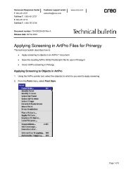
The figure below shows the user defined mask with cut windows<br />
for five (5) transparencies.<br />
❊ # ! $ # ✉ ! ❞ # ✇ ❢ ) ! ❝ ❜ ) ✳ ❞ # ❡ ❢<br />
30<br />
29<br />
28<br />
37 36 35 34 33 32 31 30 29 28 27 26 25 24 23 22 21 20 19 18 17 16 15 14 13 12 11 10<br />
7 5 4 2 1 0<br />
27<br />
26<br />
25<br />
43 42 41 40 39 38<br />
24<br />
23<br />
22<br />
21<br />
20<br />
19<br />
18<br />
17<br />
16<br />
15<br />
14<br />
13<br />
12<br />
11<br />
10<br />
9<br />
8<br />
6<br />
:❢)!;❜:❧!$❜;❢<br />
3<br />
4<br />
9<br />
8<br />
7<br />
6<br />
❚❋❙!❊❋5❏❖❋❊!7❇❚9<br />
!❙❇❖❚◗❇❙❋❖❉!!❚❏❊❋<br />
❉❜✉✴!❖#✴!509D1L005<br />
37 36 35 34 33 32 31 30 29 28 27 26 25 24 23 22 21 20 19 18 17 16 15 14 13 12 11 10<br />
7 5 4 2 1 0<br />
5<br />
4<br />
3<br />
2<br />
1<br />
0<br />
❜@❢ ✉)❜$:@❜)❢$❞A ❢;✈C:❥#$ :❥❡❢ ❡#E$<br />
43 42 41 40 39 38<br />
30<br />
29<br />
28<br />
27<br />
26<br />
25<br />
24<br />
23<br />
22<br />
21<br />
20<br />
19<br />
18<br />
17<br />
16<br />
15<br />
14<br />
13<br />
12<br />
11<br />
10<br />
7<br />
6<br />
5<br />
4<br />
3<br />
2<br />
1<br />
➤ Mount the mask (without originals) in the scanner with the<br />
transparency side facing up; insert the mask’s registration holes<br />
into the registration pins of the glass.<br />
Note: The 0,0 corner of the mask is approximately above the 0,0 corner of the Base glass.<br />
2.6<br />
Preparation
For reflective:<br />
➤ Tape the reflectives to the reflective side of the mask, according<br />
to the format you want to define. Make sure the image side is<br />
up and in the correct orientation.<br />
The first original should be near the 0,0 point at the lower left<br />
corner of the mask. Taping the originals is similar to direct<br />
mounting in multi-preview (see Direct Mount in multi-preview,<br />
above), but here you proceed from left to right. Make sure not to<br />
cover the barcode windows.<br />
PREPARATION<br />
✎ The 0,0 corner of the mask is<br />
approximately above the 0,0 corner of<br />
the Base glass.<br />
➤ To mount in the scanner, turn the mask over so that the<br />
transparency label of the mask faces up; insert the mask<br />
registration holes into the registration pins of the glass.<br />
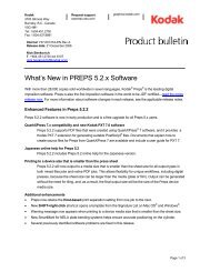
The figure below shows the prepared mask mounted for<br />
reflective scan.<br />
Transparency side<br />
✎ The reflective is taped to the other<br />
side of the mask. Therefore it is not<br />
shown in this figure.<br />
Mounting Originals 2.7
Defining a user defined format<br />
After mounting the prepared mask, follow the procedure described<br />
below to define transparency and reflective formats:<br />
➤ In the Setup dialog box, choose the All Board format.<br />
➤ Perform Preview.<br />
The Preview display window shows the entire mask.<br />
In transparency, the prepared windows are shown. In reflective,<br />
the taped originals are shown.<br />
✎ The system automatically adds<br />
1.5 mm around your crops.<br />
➤ Crop each window/original in the Preview display window.<br />
➤ From the File menu, choose Save User Defined. The Save User<br />
Defined menu appears.<br />
➤ From the Save User Defined menu, choose an option, depending<br />
on the format you want to define.<br />
➤ In the window that appears, enter the name of the new user<br />
defined format.<br />
If you define a new format under an existing format name, the new<br />
format replaces the previous one. To delete a user format, delete<br />
the format file from the Scitex Tables folder.<br />
Using user defined formats<br />
When using the mask for transparency, make sure the originals are<br />
taped to their windows, emulsion side down.<br />
After application restart, the user defined formats appear in the<br />
Format options in the Setup dialog box. Select the desired format<br />
when scanning according to this format. See Chapter 4, Basic Scan<br />
for details on the scan procedure.<br />
2.8<br />
Preparation
Slide Holder<br />
The slide holder is designed for scanning up to 20 35mm slides<br />
(framed 35mm transparencies). The slide holder is shown below.<br />
The holder has five (5) rows, each can hold four (4) slides. If<br />
necessary, a second holder can be used for scanning up to 40 slides.<br />
Using the slide holder<br />
➤ To insert slides, hold the holder with the printed side facing up.<br />
Insert the first slide, emulsion side down and in the correct<br />
orientation, into the bottom row. Push it all the way to the end<br />
of the row.<br />
➤ Insert the other three slides in the same row.<br />
➤ When the first row is full, continue to the next row, and so on.<br />
Make sure each slide is in its correct orientation. See figure<br />
below.<br />
Note: For efficient scanner work it is recommended that the bottom row is filled first,<br />
and that each row is filled starting at the end of the row.<br />
PREPARATION<br />
Inserting slides into the slide holder<br />
Mounting Originals 2.9
➤ Mount the holder in the scanner with the printed side facing up;<br />
insert the two (2) right registration holes of the holder into the<br />
two right registration pins of the Base glass (the left hole and pin<br />
are not used). The right side of the holder should be aligned<br />
with the right side of the glass.<br />
➤ For more than 20 slides, use the second slide holder. Insert the<br />
slides in the second holder in the same manner as in the first<br />
holder.<br />
➤ Mount the second slide holder in the scanner next to the first<br />
holder; insert the left registration hole of the holder into the left<br />
registration pin of the Base glass. Make sure the jigsaw edges of<br />
the two holders interlock. See figure below.<br />
Two slide holders mounted in the scanner<br />
➤ In Setup mode, choose 35mm slide holder or 2 x 35mm slide<br />
holder from the Format options in the Setup dialog box,<br />
depending on the mounted holders. See Chapter 4, Basic Scan<br />
for details on the scan procedure.<br />
2.10<br />
Preparation
3<br />
TOOLS & PALETTES<br />
In this chapter you will learn how to use the application tools and palettes. The<br />
keyboard controls and shortcuts appear at the end of the chapter.<br />
Overview<br />
✎ The Layout display is described in<br />
Chapter 4, Basic Scan.<br />
The application tools are divided into:<br />
• Tools controlling the foreground operations:<br />
• Preview Browser<br />
• Scan palette<br />
• Queue window<br />
• Windows palette<br />
• Layout display<br />
✎ The Setup dialog box is described<br />
in Chapter 4, Basic Scan.<br />
• Tools for defining and editing an image:<br />
• Setup dialog box<br />
• Image display window with its tools and display options<br />
• Image palette<br />
As with other Macintosh applications, the window must be active<br />
if you want to use it. Click the window to activate it. (The Setup<br />
dialog box and the palettes are always active).<br />
TOOLS & PALETTES<br />
Overview 3.1
The following figure is a schematic view of your desktop, showing<br />
the various windows and tools.<br />
Menu bar<br />
Setup dialog<br />
box<br />
Image display<br />
window<br />
Image palette<br />
Scan palette<br />
Preview browser<br />
Windows palette<br />
Queue window<br />
3.2<br />
Tools & Palettes
Preview Browser<br />
The Preview Browser controls the operational stage of the previews.<br />
It also gives the status of each original in the scanner. The figure<br />
below shows the Preview Browser.<br />
Preview Browser window - Show Preview family<br />
Each window in the Preview Browser represents an image. An<br />
empty gray window indicates that the image has not been<br />
previewed. After Preview, Crop Prescan or Max Detail an image<br />
thumbnail appears in the window.<br />
For example, the preview family shown in the above figure shows the thumbnails of a<br />
preview, two crop prescans and two max details.<br />
TOOLS & PALETTES<br />
Use the Preview Browser to control the following operations:<br />
• To display an image in the Image display window, double click<br />
its image thumbnail.<br />
• Selecting images into the Queue window for preview or final<br />
scan. For preview, click the empty gray window. For scan, click<br />
the image thumbnail (this is possible only if the Image display<br />
window is closed).<br />
Note: To select more than one image, click each image while pressing Shift.<br />
Alternatively, encompass the required images with a rectangle while holding down and<br />
dragging the mouse button.<br />
Preview Browser 3.3
The Preview Browser provides the following status information:<br />
• Format and number of originals in the scanner, and the file<br />
names of scanned images.<br />
• Specific icons indicate if preview, crop prescan, max detail or<br />
final scan were performed. Blue icons mean that the image was<br />
interactively modified (see figure below).<br />
• An arrow appears below the thumbnails of images currently in<br />
the queue, waiting to be scanned.<br />
• The thumbnail of an image currently displayed in the Image<br />
display window is dimmed.<br />
The figures below show the image thumbnail and various icons<br />
that may appear in the Preview Browser window.<br />
3.4<br />
Tools & Palettes
✎ These screens appear in the Help<br />
menu, under the Apple in the Menu bar.<br />
The three display options of the Preview Browser:<br />
Click the relevant icon to choose the display option.<br />
TOOLS & PALETTES<br />
Show All; expanded Preview Browser, showing all thumbnails (all<br />
previews, crop prescans and max details).<br />
Show Previews; show only Previews (one thumbnail per preview).<br />
Show Preview family; show one Preview and its crop prescans and<br />
max details (see figure at beginning of this section).<br />
Preview Browser 3.5
Scan Palette<br />
The Scan palette is used to perform preview, crop prescan and final<br />
scan, and restart the application. The Scan palette is always<br />
displayed on the desktop when the application is open. The echo<br />
line, at the bottom of the palette, describes the icon at the pointer’s<br />
position. The active icons depend on the current mode of operation.<br />
To select a function, click its icon. When an image is displayed in<br />
the Image display window, the selected function is performed on the<br />
image; when an image is not displayed, the function is performed<br />
on selected preview thumbnails in the Preview Browser.<br />
The Scan palette includes:<br />
Preview icon; active in Setup mode, when there is an image to be<br />
previewed.<br />
Prescan icon; active in Preview mode, when a crop (not yet<br />
prescanned) is defined on the displayed Preview. To prescan all<br />
crops on the Preview, press the key and click the multiprescan<br />
icon that appears.<br />
Scan icon; active in Preview mode, when there is a preview or crop<br />
to be scanned. To scan all crops on the Preview, press the<br />
key and click the multi-scan icon that appears.<br />
Restart icon, to return the application to Setup mode.<br />
Note: The Scan palette functions can also be selected from the Scan menu in the<br />
Menu bar.<br />
3.6<br />
Tools & Palettes
Queue Window<br />
The Queue window manages the background operation of the<br />
scanner, that is, manages your scanning requests.<br />
Images selected from the Preview Browser for preview or scan, enter<br />
the Queue window. Crop prescan and max detail requests also<br />
enter the queue. The item is scanned when it reaches the top of the<br />
queue, and a Progress indicator appears below this item. You can<br />
edit the queue, as explained below.<br />
✎ When you enter the application or<br />
after Restart, the queue is empty.<br />
TOOLS & PALETTES<br />
Queue window with: max detail currently being scanned;<br />
one preview, crop prescan group, and one final scan.<br />
The queue order is according to a fixed priority. The priority order<br />
is: max detail, preview, crop prescan, and final scan. Within each<br />
priority group, items are arranged according to the order in which<br />
they entered the queue.<br />
To minimize the Queue window, press the zoom box (upper right).<br />
The window then shows only the item currently being scanned and<br />
a Progress indicator. In the full Queue window, the scroll bar on the<br />
right side is used to scroll the window.<br />
Queue Window 3.7
Each queue item has the following:<br />
• Serial number, indicating position in the queue. The item<br />
currently being scanned is number 1 with an arrow, and colored<br />
green. Serial numbers are constantly updated, as items enter or<br />
leave the queue and/or you edit the queue.<br />
• Image file name.<br />
• An icon indicating if the item is waiting in the queue for<br />
preview, crop prescan, max detail or final scan.<br />
Editing the queue:<br />
• To rearrange the queue, select and drag the item to its new<br />
position. All other items are automatically rearranged. In<br />
Prescan All or Scan All, items belonging to the same Preview<br />
are grouped together (enclosed by a box). You cannot divide<br />
the group, or move a group item.<br />
Note: If grouped items are processed when a max detail enters the queue, the group is<br />
divided. The max detail enters the top of the queue and the unprocessed group items<br />
are scanned after the max detail.<br />
• To delete an item or a group waiting in the queue, select it and<br />
press the key. You cannot delete items within the<br />
group.<br />
• To delete an item currently being scanned (the top most item),<br />
select it and press . The system prompts for one of<br />
two options: delete the item from the queue, or re-enter it into<br />
the queue. If you choose to re-enter, the item enters the queue<br />
according to its priority. For example, a preview is re-entered as the last item<br />
in the preview group.<br />
3.8<br />
Tools & Palettes
Windows Palette<br />
The Windows palette opens and activates the following application<br />
windows:<br />
• Setup dialog box<br />
• Preview Browser<br />
• Scanner Queue<br />
• Layout display<br />
In the Windows palette, click the relevant icon to open the requested<br />
window (if it is closed) and activate it. This is also useful if the<br />
window is hidden by other windows.<br />
If the Windows palette is not open or not shown, select Windows<br />
palette from the Windows menu in Menu bar.<br />
To close the Windows palette, click its close box.<br />
TOOLS & PALETTES<br />
Windows Palette 3.9
Image Display Window<br />
The Image display window is used for interactive work with the<br />
image. The window includes the display area, and various tools and<br />
display options that are arranged along the left and bottom sides of<br />
the display area. The figure below shows the Image display window.<br />
UCR indicator<br />
Split screen<br />
Tools<br />
Display<br />
area<br />
File information<br />
Floating<br />
densitometer<br />
Display<br />
separations<br />
Split screen<br />
3.10<br />
Tools & Palettes
Display Area<br />
Split Screen<br />
✎ The densitometer reading shows both<br />
the before and after values. See Floating<br />
Densitometer, further on in this chapter.<br />
After Preview, the first Preview image is automatically displayed in<br />
the display area. To display a prescanned image, double click its<br />
image thumbnail in the Preview Browser.<br />
For the displayed image you can:<br />
• select an editing function. In interactive functions, you can<br />
view applied changes and compare the before/after display. See<br />
Split Screen, below.<br />
• select a cropping or sampling tool.<br />
• choose a display option.<br />
In addition, the letters U, G or A appear in the upper right side of<br />
the display area if UCR, GCR or UCA is active during preview.<br />
See Chapter 6, Color, Separation Setup.<br />
Split screen is a convenient tool during interactive editing, for<br />
comparing the image before and after update. When you open an<br />
interactive function, two handles appear at the right side of the<br />
Image display window; the upper handle for horizontal split, the<br />
bottom handle for vertical split.<br />
➤ Drag the horizontal (or vertical) handle to the location at which<br />
you want to split the image. In horizontal split, the area above<br />
the marker is before Apply, the area below the marker is after<br />
Apply. In vertical split, the area to the left is before, the area to<br />
the right is after.<br />
➤ For comparison purposes, you might want to display the same<br />
image area in the two sections of the split window. Using the<br />
scroll bars, scroll the split image so that the same image area is<br />
shown in each section.<br />
➤ Move the handle to reposition the marker; double click the<br />
handle to cancel the split screen and restore the full display.<br />
TOOLS & PALETTES<br />
Image Display Window 3.11
Tools and Display<br />
Options<br />
This section describes the cropping and sampling tools, and the<br />
display and information options that appear along the left and<br />
bottom sides of the display area. These are used when viewing the<br />
image and when performing interactive editing.<br />
When the Preview is first displayed in the Image display window, a<br />
crop frame encloses the image. This is the Full image crop, set<br />
according to the selected format. The area enclosed by the crop<br />
frame is the final scan area. Using the cropping tools, you can<br />
change the crop size and position.<br />
Note: The following elements are described in the order in which they are arranged, starting<br />
from the upper left corner.<br />
This is the system default pointer, used to change the position and<br />
size of the crop frame.<br />
➤ Select the pointer and move it inside the crop frame.<br />
➤ When you press the mouse button, the pointer changes to a<br />
Hand. Drag the Hand to move the frame, and release the mouse<br />
to set the new position.<br />
To change the crop size:<br />
➤ Move the pointer to a frame corner or to the center marker of<br />
one of its sides. The pointer changes to a set of arrows, pointing<br />
in the directions that you may move the frame.<br />
➤ Press the mouse button and drag the frame side or corner;<br />
release the mouse to set the frame size.<br />
Cropping<br />
To define and draw a new crop.<br />
➤ Select the tool and click a point in the image to mark the top left<br />
corner of the crop.<br />
➤ Press and drag the mouse button to the desired lower right<br />
corner. Release the mouse to set the crop.<br />
3.12<br />
Tools & Palettes
➤ To move or change the crop size, use the system default pointer<br />
(see previously).<br />
Note: To reset the crop to the Full image crop, double click the Cropping icon, or click<br />
the Reset Crop tool (see further on).<br />
Scaling<br />
To set the enlargement of the final scan, using the Two-point<br />
method. In the Two-point method, the system calculates the scale<br />
based on the input and output sizes. The input size is the actual<br />
distance between two points on the original; the output size is the<br />
distance between the two points in the final scan; the scale is the<br />
ratio between the output and input sizes.<br />
➤ Select the Scaling tool and click the first point in the image (do<br />
not release the mouse).<br />
➤ Drag the mouse to the second point and release. The Scaling<br />
dialog box opens. The Input Size is the original distance<br />
between the two marked points.<br />
TOOLS & PALETTES<br />
➤ In the Output Size field, enter the output distance between the<br />
points (that is, the desired distance in the final scan).<br />
➤ Click OK. The system calculates the new value and updates the<br />
Scale value in the Setup dialog box.<br />
Reset Crop<br />
Click this tool to set the crop to the Full image crop.<br />
Tools and Display Options 3.13
Max Detail<br />
To perform a max detail prescan. This option is useful for<br />
examining the results of sharpness, and/or edit the sharpness<br />
parameters. For details, see Chapter 7, Sharpness, Max Detail.<br />
Sample Points<br />
Show/Hide End Points<br />
Active when the Preview window is shown. This tool is used to<br />
temporarily show or hide the End Points. For details, see Chapter 5,<br />
End Points.<br />
Sampling points from the image is possible when performing<br />
interactive image editing. Two tools are relevant to this function:<br />
Sampler and Show/Hide Sample Points. See following description.<br />
Sampler<br />
The Sampler is active in interactive editing functions, such as<br />
Gradation and End Points. It is used to sample points from the<br />
image and see the effect of your changes.<br />
➤ When an edit dialog box is open, click the Sampler tool. The<br />
Sample Points dialog box appears.<br />
Sample Points dialog box - before sampling<br />
➤ Using the Sampler, click a point on the image.<br />
Note: To sample points, the Sampler must be active. If inactive, click the Sampler at the<br />
upper left corner.<br />
The CMYK or RGB values and the color patch of the selected<br />
point are shown. This is a floating sample point, as it changes<br />
when you click the Sampler on other points.<br />
3.14<br />
Tools & Palettes
➤ Click Add to set the point as a fixed point that remains on the<br />
image. The dialog box expands, and the color patch and values<br />
appear in the first fixed point section.<br />
You can select additional sample points in the same manner.<br />
As you Add points, the dialog box expands to display the new<br />
fixed points.<br />
✎ The sample points are deleted when<br />
you exit the application.<br />
Sample Points dialog box - after sampling<br />
➤ You can continue sampling floating points; each new point<br />
replaces the current floating point.<br />
➤ To delete a fixed point, select the relevant section in the dialog<br />
box and click the Trash icon.<br />
TOOLS & PALETTES<br />
Before image editing changes, the After colors of the sample points<br />
are identical to the Before ones. However, when using an editing<br />
function, such as Gradation, your changes are shown in the After<br />
colors.<br />
➤ To close the Sample Points dialog box, click its close box.<br />
(In addition, the dialog box automatically closes when you exit<br />
the editing function.) The fixed sample points remain marked<br />
on the image when the Sample Points dialog box is closed (see<br />
Show/Hide Sample Points, below).<br />
Tools and Display Options 3.15
➤ To open the Sample Points dialog box, click the Sampler tool.<br />
The dialog box opens with the existing fixed sample points.<br />
Show/Hide Sample Points<br />
Active after sample points are selected with the Sampler (see above).<br />
This tool is used to temporarily show or hide the sample points on<br />
the image.<br />
➤ If the sample points are not shown, click the icon to show the<br />
points on the image. To open the Sample Points dialog box or to<br />
add/delete points, you must select the Sampler tool (see above).<br />
➤ If the sample points are shown, click the icon to temporarily<br />
hide them. The points are not deleted; if you click the icon<br />
again, they reappear.<br />
Lineart/B/W Display<br />
Active only in Lineart mode, where two display options are<br />
available. Click the requested icon:<br />
Line-art (for black and white pixels only)<br />
B/W (for black, grays and white).<br />
Note: In B/W mode, there are no display options.<br />
Show/Hide Sharp Effects<br />
Active after Max Detail, and only if the max detail is displayed in<br />
the Image display window.<br />
The results of sharpness editing can be viewed only in max detail<br />
and only if the sharp effects are shown. The max detail image is<br />
automatically displayed with the sharp effects on. Click the icon to<br />
show or hide these effects, as desired. For details, see Chapter 7,<br />
Sharpness, Max Detail.<br />
3.16<br />
Tools & Palettes
File Information<br />
The file size appears at the bottom left corner of the Image display<br />
window. The file size in KB (thousands of bytes) is the size of the<br />
final scan file, based on current scan file settings.<br />
➤ Press the File Size field to open the File Information window.<br />
Floating Densitometer<br />
The floating densitometer, at the bottom of the Image display<br />
window, shows the values at the pointer’s current location. The<br />
densitometer reading depends on the selected Mode and on the<br />
defined densitometer setup (see Chapter 9, Setup, Densitometer<br />
Setup).<br />
When using the split screen in interactive editing, the densitometer<br />
reading shows both the before and after values for each separation.<br />
TOOLS & PALETTES<br />
Tools and Display Options 3.17
Display Separations<br />
Only for CMYK and RGB Color modes. The Display separation<br />
fields appear at the bottom of the Image display window, to the right<br />
of the floating densitometer.<br />
The available display options are determined by the selected Mode<br />
in the Setup dialog box:<br />
For CMYK color: CMYK, Cyan, Magenta, Yellow, Black<br />
✎ In B/W and Line-art modes, only<br />
the black separation is displayed.<br />
For RGB color: RGB, Red, Green, Blue<br />
For the displayed image, click the icon of the separation you want<br />
to display. Choose all separations (CMYK or RGB) or a single<br />
separation.<br />
When you change the Mode, the Display separation fields are<br />
updated accordingly.<br />
3.18<br />
Tools & Palettes
Image Palette<br />
The Image palette appears after Preview and if an image is<br />
displayed. Its icons represent the main image editing functions.<br />
The echo line at the bottom of the palette, describes the icon at the<br />
pointer’s position. To select a function, click its icon. The function<br />
dialog box appears and the palette closes temporarily until you exit<br />
the dialog box.<br />
✔ Split screen is available for all<br />
interactive functions accessed in this<br />
palette. See Split Screen previously<br />
in this chapter.<br />
Image palette features:<br />
• Active icons depend on the Mode and Media of the displayed<br />
image. For example, Filmtype is active only for color negatives.<br />
• The icons are arranged, from left to right in a recommended<br />
order in which you should use the functions. End Points is the<br />
first icon, since it is the first function you should use if image<br />
editing is necessary.<br />
The Image palette icons (from left to right):<br />
End Points, in Color and B/W modes to adjust the End Points.<br />
TOOLS & PALETTES<br />
Filmtype, only for color negatives to modify/save Filmtype tables.<br />
Gradation, in Color and B/W modes to create/modify Gradation<br />
tables.<br />
Sharpness to edit the Sharpness table.<br />
Color Correction, only in Color modes to edit the Color table.<br />
Line-art, only in Line-art mode to set the Line-art Controls.<br />
Image Palette 3.19
Keyboard Controls<br />
✎ All keyboard controls are listed<br />
under Help in the Apple menu.<br />
The following keyboard controls are available in the application.<br />
Control<br />
To see only the crop area. Press the key to display the<br />
area outside the crop in white.<br />
Option/Alt<br />
Press the key to change the Prescan and Scan icons in<br />
Scan palette to Prescan All and Scan All.<br />
Shift in image display window<br />
To maintain the crop proportions when changing the crop size.<br />
When you press , the frame increases/decreases in size, but<br />
the height/width ratio does not change.<br />
Shift in Preview Browser<br />
To select multiple items in the Preview Browser window. Press<br />
and click on the items.<br />
Shift in Queue Window<br />
To select multiple items in the Queue window. Press and<br />
click on the items.<br />
Shift in Sample Points dialog box<br />
To add fixed sample points. Press and click on the sample<br />
points.<br />
Shift in End Points dialog box<br />
In Set White (Dark) Pt, if you press while setting the<br />
White (Dark) point, the Sampler remains active.<br />
✎ If the active crop is a Full picture<br />
crop, it cannot be deleted.<br />
Delete in Image display window<br />
To delete the active crop.<br />
Delete in Setup dialog box<br />
To delete the value in the active text field.<br />
3.20<br />
Tools & Palettes
Delete in Queue Window<br />
To delete selected items from the queue.<br />
Tab in Image display window<br />
To cycle among the crops until the desired crop is active.<br />
Tab in Setup dialog box<br />
To move to the next text field.<br />
TOOLS & PALETTES<br />
Keyboard Shortcuts 3.21
Keyboard Shortcuts<br />
✎ All keyboard shortcuts are listed<br />
under Help in the Apple menu.<br />
3.22<br />
The following keyboard shortcuts are available in the application.<br />
< >B B/W or Line-art display in Line-art mode<br />
< >D Duplicate Crop<br />
< >E Open the End Points function<br />
< >F Show/Hide Sharp Effects<br />
< >G Open the Gradation function<br />
< >H Perform Crop Analyze<br />
< >J Open the Color Correction function<br />
< >K Open the Operation Modes Preferences<br />
< >M Open the Sharp function<br />
< >N Open the Negative Balance function for Negatives<br />
< >P Perform Preview<br />
< >Q Quit application<br />
< >R Restart application<br />
< >S Save Params for Scan<br />
< >T Set the Line-art threshold in Line-art mode<br />
< >U Unlock Crop<br />
< >W Close Window<br />
< >+/- Increase/decrease the Max Detail area<br />
< >0 Show All Separations<br />
< >1 Show Cyan Separation<br />
< >2 Show Magenta Separation<br />
< >3 Show Yellow Separation<br />
< >4 Show Black Separation<br />
Tools & Palettes
4<br />
BASIC SCAN<br />
In this chapter, you will learn how to perform a basic scan of a color transparency,<br />
including:<br />
• Entering the application<br />
• Setup mode, including Setup dialog box and Layout display<br />
• Performing a preview and Preview mode options<br />
• Performing a final scan<br />
Note: Other types of originals have unique options and settings. See Chapter 8, Special<br />
Workflows.<br />
Entering Application<br />
➤ Make sure that your scanner and Macintosh are on.<br />
➤ Double click the <strong>EverSmart</strong> <strong>Jazz</strong> icon located in the<br />
<strong>EverSmart</strong> <strong>Jazz</strong> folder.<br />
The <strong>EverSmart</strong> <strong>Jazz</strong> Opening display appears on screen for a few<br />
seconds, followed by the Setup dialog box and Menu bar. You have<br />
now entered the scanning application.<br />
Note: If the application cannot locate the Scitex Tables folder, a folder selection dialog box<br />
appears. In the dialog box, select Scitex Tables folder and click Set.<br />
➤ Mount the originals that you want to scan in the scanner. See<br />
details in Chapter 2, Preparation, Mounting Originals.<br />
Whenever you want to close the application, from the File menu in<br />
the Menu bar, choose Quit.<br />
BASIC SCAN<br />
Entering Application 4.1
Setup Mode<br />
When you first enter the application, the Setup dialog box in Setup<br />
mode appears, as shown below.<br />
✎ The ICC Flow icon appears in the<br />
dialog box if this option is used. See<br />
Chapter 8, Special Workflows, ICC<br />
Profile.<br />
✎ Restart in the Scan palette can be<br />
used to re-enter Setup mode.<br />
Setup dialog box - Setup mode<br />
The Setup dialog box defines the various parameters to be used<br />
during the Preview process.<br />
The Setup dialog box is divided into three sections:<br />
• Original and format parameters<br />
• Size and scale parameters<br />
• Image adjustment parameters<br />
4.2<br />
Basic Scan
Setup Parameters<br />
Type<br />
➤ From the Type list, choose Transparent or Reflective, according<br />
to the type of original.<br />
➤ For transparent, choose one of the options:<br />
• Regular - for masked or direct mount originals<br />
• Framed - for framed originals<br />
• Mixed - not yet available<br />
➤ For reflective, choose one of the options:<br />
• Regular - for reflectives with a smooth surface<br />
• Pasteup - for reflectives that have something pasted on<br />
them, such as a label.<br />
Mode<br />
➤ From the Mode list, choose Color CMYK, Color RGB, B/W or<br />
Line-art depending on desired output.<br />
Choose Color CMYK for printing systems; choose Color RGB for<br />
multi-media systems that require RGB values.<br />
Choose B/W to create a B/W file from a color image, taking into<br />
consideration all the image colors, or to create a B/W file from a<br />
B/W image. One separation is created in the final scan.<br />
Choose Line-art for a Line-art scan, where the created image is in<br />
black and white only.<br />
Note: You can switch between the Color and B/W modes also after Preview. In Line-art,<br />
you cannot change the mode.<br />
The RGB, B/W and Line-art scans are described in Chapter 8,<br />
Special Workflows.<br />
BASIC SCAN<br />
Setup Mode 4.3
Format<br />
✎ Creating user formats with the user<br />
defined mask is described in Chapter 2,<br />
Preparation, User Defined Mask.<br />
The application is supplied with standard formats, according to the<br />
selected Mode option. Format options for Color RGB/CMYK and<br />
B/W modes are shown below. Line-art mode is discussed in<br />
Chapter 8, Special Workflows, Line-art Mode. In addition to the<br />
standard formats, user defined formats that you have created are<br />
also listed. The various formats are detailed below.<br />
➤ From the Format list, choose your format; if your format is not<br />
listed, use the Layout display to modify the scan area (see Layout<br />
display, further on) or choose a format closest to your format<br />
and modify it after Preview.<br />
✎ All standard formats are defined<br />
starting at the 0,0 corner of the Base<br />
glass.<br />
The Preview Browser is set according to selected format, and the<br />
format name appears in the Preview Browser. In single preview<br />
formats (such as 35mm), a single preview window is shown. In<br />
multi-preview formats, the number of windows depends on<br />
number of previews.<br />
✎ When you first enter the<br />
application, the Format and Preview<br />
Browser are set according to the<br />
previous run.<br />
Transparency<br />
Reflective<br />
Strip 80mm (transparency)<br />
This option is used to scan many originals of a width up to 80mm<br />
in a shorter scanning period. The originals are placed along a<br />
80mm wide strip, starting at the 0,0 lower right corner and<br />
extending the entire length of the Base glass. The scanner prescans<br />
the entire strip and displays the originals as a single preview.<br />
4.4<br />
Basic Scan
35mm, 6x6, 6x7, 4x5, 8x10H/V (transparency)<br />
Single preview formats for originals that correspond to the format<br />
size.<br />
All Board (transparency/reflective)<br />
In All Board, the entire board is scanned and the originals are<br />
displayed as a single preview.<br />
35mm slide holder / 2 x 35mm slide holder<br />
Multi-preview formats for 35mm slides that are mounted in the<br />
scanner using a specially designed slide holder. See Chapter 2,<br />
Preparation, Mounting Originals for details on using the holder.<br />
Choose 35mm slide holder when one slide holder is mounted (up<br />
to 20 slides); choose 2 x 35mm slide holder when two holders are<br />
mounted (up to 40 slides).<br />
✎ Custom format appears if you<br />
modified the scan area in the Layout<br />
display in the current run without using<br />
save (see Layout display further on in<br />
this chapter).<br />
User defined formats<br />
User defined formats are custom made transparency and reflective<br />
formats. User defined formats for masked originals are described<br />
in Chapter 2, Preparation, Mounting Originals, User Defined Mask.<br />
User defined formats for unmasked originals are described further<br />
on in the Layout display.<br />
Media<br />
From the Media list, choose Positive or Negative, according to your<br />
original. In multi-preview, if you have positive and negative<br />
originals, choose the option that is relevant to most of the originals,<br />
and then choose the correct option after Preview.<br />
BASIC SCAN<br />
Setup Mode 4.5
Smooth<br />
In some cases, a certain amount of smoothening is required:<br />
• The dot pattern might be visible in printed material.<br />
Descreening blurs the dot pattern without degrading the<br />
image.<br />
• Lines might appear with jagged edges. Anti-alias minimizes<br />
the pixel contrast at the edges, causing them to be smoother and<br />
blend in the background. It can also remove unwanted moiré.<br />
Smooth options include:<br />
• None, no smoothening effect.<br />
• Descreen1 to Descreen10, descreening levels for printed<br />
material (see Chapter 8, Special Workflows, Printed Material).<br />
• Anti-alias normal, Anti-alias strong, two levels of anti-alias for<br />
lines.<br />
The effect of smooth can be seen in the final scan or in max detail<br />
(see Chapter 7, Sharpness, Interactive Sharpness Editing).<br />
Unit of Measurement<br />
Choose inches, mm, points or picas as the unit of measurement for<br />
the Crop Height/Width and Scan Height/Width fields.<br />
Scale<br />
Sets the enlargement by which the scanner scans the original.<br />
A scale of 100% means no change.<br />
The Scale and Resolution values are related.<br />
For the <strong>EverSmart</strong> <strong>Jazz</strong>, the maximum scale/resolution for all<br />
formats is 2000% at 12 DPM (300 DPI).<br />
For the <strong>EverSmart</strong> <strong>Jazz</strong>+, the maximum scale/resolution for all<br />
formats is 2540% at 12 DPM (300 DPI).<br />
4.6<br />
Basic Scan
Mirror<br />
Check the Mirror box to create a mirror image of the scanned<br />
original. Note: When mounting a duplicate, place it emulsion side down and use<br />
Mirror to obtain a correct image<br />
Resolution<br />
Resolution specifies the number of dots (pixels) per millimeter or<br />
inch of the final image, and is related to the halftone screen.<br />
When setting the resolution, you should consider the screen.<br />
For higher or finer screens, the resolution value should be higher to<br />
capture the additional information.<br />
The minimum output resolution is 2 DPM (51 DPI).<br />
Resolution and Scale are related, as explained in Scale, above.<br />
For the <strong>EverSmart</strong> <strong>Jazz</strong>, the maximum resolution for all formats is<br />
236 DPM (6000 DPI). For the <strong>EverSmart</strong> <strong>Jazz</strong>+, the maximum<br />
resolution for all formats is 300 DPM (7620 DPI).<br />
A rule of thumb formula, commonly used to determine the final<br />
resolution, is as follows:<br />
Halftone screen per inch (or per mm) x 2.0 = resolution in dots per inch (DPI) or<br />
per mm (DPM).<br />
For example, an image to be output as an 150 LPI halftone is calculated: 150 x 2.0 = 300<br />
DPI. Therefore, the resolution is set at 300 DPI.<br />
Choose DPM (dots per millimeter) or DPI (dots per inch) as the<br />
resolution unit of measurement, and enter the requested resolution<br />
value.<br />
End Points, Gradation, Color Table and Sharpness<br />
Make sure the End Points are set to AutoNormal, and the<br />
Gradation, Color Table and Sharpness are set to their default tables.<br />
Note: Filmtype appears only for color negatives. See Chapter 8, Special Workflows, Color<br />
Negatives.<br />
BASIC SCAN<br />
Setup Mode 4.7
SmartSet<br />
You can choose from among several, pre-defined SmartSet tables<br />
that are related to certain subjects, and can be applied to scans.<br />
Each SmartSet table is constructed to accommodate a broad range<br />
of variables within a general subject matter. Every SmartSet table is<br />
comprised of several different tables that normally would have to<br />
be loaded manually.<br />
SmartSet Tables:<br />
• End Points<br />
• Gradation<br />
• Color<br />
• Sharpness<br />
• Filmtype<br />
Note: Filmtype appears only for color negatives. See Chapter 8, Special Workflows, Color<br />
Negatives.<br />
SmartSet in the Setup window<br />
Make your selection in SmartSet according to the main subject of<br />
your scan. The application loads an appropriate group of tables.<br />
You can define a new SmartSet by loading different tables. The<br />
SmartSet name changes to Custom, and then you can save the<br />
new SmartSet with a name you choose.<br />
You can also customize additional tables according to your own<br />
requirements and save them for later use.<br />
To save a SmartSet, you must save any table that is labeled Custom<br />
with a new name. In other words, you cannot save a SmartSet with<br />
a table labeled Custom.<br />
The SmartSet tables can incorporate any of the application features<br />
that are described in Chapters 5, 6 and 7.<br />
4.8<br />
Basic Scan
Layout Display<br />
The Layout display reflects the selected Format option (see Format<br />
previously). You can use the Layout display to modify the scan area<br />
before preview. In some cases, this can reduce the scan time, and the<br />
displayed preview image is larger. The Layout display is useful in<br />
the following cases:<br />
• When the mounted originals are not according to pre-defined<br />
formats, which include the standard application formats and<br />
created user defined formats.<br />
• In multi-preview formats, when you want to scan only some of<br />
the originals.<br />
To use the Layout display:<br />
✎ The Layout display automatically<br />
appears if you checked the Open<br />
Layout Display after Restart in<br />
Operation Modes, under the Setup<br />
menu.<br />
➤ After selecting a Format option, click the Layout display icon in<br />
the Windows palette. The Layout display appears, showing the<br />
Base glass and a window(s) representing the selected format.<br />
➤ In single preview formats, you can change the scan area size: click<br />
and drag one of the window corners (marked by an arrow);<br />
release to define a new window. This window marks the<br />
effective scan area, and/or:<br />
Change the scan area location: click inside the window and<br />
move it to the desired location.<br />
Note: Since the Layout display does not show the mounted originals, it is helpful to<br />
note and write down the size and location when mounting the originals in the scanner<br />
(see Chapter 2, Preparation, Mounting Originals).<br />
➤ In multi-preview formats, e.g., 35mm slide holder, select the<br />
windows you want to scan by clicking each window while<br />
pressing , or encompassing the required windows with<br />
a rectangle while holding down and dragging the mouse<br />
button.<br />
BASIC SCAN<br />
Note: Using the Layout display is easier than selecting from the Preview Browser,<br />
because the Layout display shows an accurate mapping of the slide holder, thus<br />
making it easier to select the exact windows for scan.<br />
Sharpness 4.9
➤ Click the Preview icon in the Scan palette to send the defined<br />
window(s) to the Queue window for preview.<br />
The Layout display with a window representing the 4x5” format<br />
is shown below.<br />
Layout display showing the 4x5” format<br />
4.10<br />
Basic Scan
To update or save the format:<br />
In single preview, Format in the Setup dialog box automatically<br />
becomes custom when you modify the scan area in the Layout display,<br />
and the Preview Browser is updated accordingly.<br />
➤ In Multi-preview formats, click Set in the Layout display to update<br />
the Format and Preview Browser. The Format and Preview Browser<br />
become custom.<br />
➤ In single and multi-preview formats, you can save the modified<br />
format. To do so, click Save in the Layout display and enter the<br />
new format name in the window that appears. The Format and<br />
Preview Browser are updated with the new name. The new format<br />
is not deleted when you exit the application, and is available for<br />
future use.<br />
BASIC SCAN<br />
Sharpness 4.11
Performing Preview<br />
After setting the necessary parameters in the Setup dialog box, you<br />
can preview the originals. Preview creates a low resolution scan of<br />
the image.<br />
➤ Click the Preview icon in the Scan palette, or choose Preview<br />
from the Scan menu in the Menu bar.<br />
All originals in the scanner are sent to the queue for preview. If<br />
you modified the effective scan area using the Layout display, only<br />
originals within this area will be previewed. In the Preview Browser,<br />
a Preview icon with an arrow indicates that the item is in the queue.<br />
A Progress Indicator is displayed during the preview process.<br />
When the preview is completed, the first original appears in the<br />
Image display window (shown below). You are now in Preview<br />
mode, described in the next section.<br />
4.12<br />
Basic Scan
Preview Mode<br />
This section describes how to prepare the Preview for final scan,<br />
including:<br />
• Setup dialog box options<br />
• Preview cropping and multi-crop<br />
• Saving user defined formats<br />
• Performing Crop Prescan<br />
• Performing final scan<br />
In Preview mode, the following items appear on the desktop:<br />
• A low resolution image of the first original is shown in the<br />
Image display window.<br />
• The Setup dialog box is set to the displayed Preview.<br />
• An image thumbnail of each Preview appears in the Preview<br />
Browser, with the Preview name and the Preview icon. The<br />
thumbnail of the displayed Preview is dimmed.<br />
• The Scan and Image palettes with the relevant active tools.<br />
Setup dialog box<br />
✎ The image thumbnail in the Preview<br />
Browser does not change after you<br />
change the Mode or Media options.<br />
In the Setup dialog box - Preview mode, you can perform the<br />
following:<br />
➤ In Color or B/W modes, you can switch between Color<br />
RGB/CMYK and B/W modes (you cannot choose Line-art).<br />
➤ In multi-preview with positive and negative originals, the<br />
selected Media might not be correct for the displayed Preview. In<br />
this case, choose the correct option, Positive or Negative and<br />
click Apply.<br />
➤ You can change the Scale value, by entering a new value or<br />
using the Scaling tool (on left side of display area).<br />
➤ You can choose another End Points, Gradation, Sharpness or<br />
Color tables.<br />
Whenever the image can be updated, Apply becomes active.<br />
For example, after defining a crop, Apply performs a crop analysis and selects new end<br />
points, or after changing the Color table, Apply updates the image with the new table.<br />
BASIC SCAN<br />
Preview Mode 4.13
Crop and Multi-Crop<br />
✎ If the crop extends beyond the<br />
display area boundaries, the extended<br />
area is scanned in black.<br />
When the Preview is first displayed, the Full image crop is defined,<br />
enclosing the entire image. The system assigns a default name<br />
Scan_X_1 to this crop, where X is the Preview number. You can<br />
modify the crop and create additional crops.<br />
Cropping the Preview<br />
➤ You can modify the Full image crop, decrease its size or move it<br />
to a different location (see Chapter 3, Tools & Palettes, Tools &<br />
Display Options).<br />
➤ To define a new crop, use the cropping tools (see the reference<br />
above) or enter new Crop Height/ Width values.<br />
Note: The Full image crop no longer exists after it is modified or a new crop is created.<br />
If you change the Crop Height/Width proportionally, using the<br />
key, the Scale value changes but the Scan Height/Width<br />
remain constant.<br />
If you change Scale, the Crop Height/Width or Scan Height/Width<br />
change accordingly, depending on which was modified last.<br />
A Warning icon appears in the Setup dialog box if the scan cannot<br />
be performed according to the defined settings, because these<br />
settings exceed the scanner limitations. For example:<br />
• Crop is too small (less than 65 pixels in the output width).<br />
• More than 32,000 pixels in the output width, and 65,000 in the<br />
output height.<br />
• Scale is higher than the maximum value; in resolution 12 DPM<br />
(300 DPI) more than 2000% for <strong>EverSmart</strong> <strong>Jazz</strong> and 2540% for<br />
<strong>EverSmart</strong> <strong>Jazz</strong>+.<br />
• Resolution is less than 2 DPM (51 DPI).<br />
• When the entire image is scanned in maximum scale and with a<br />
scan margin.<br />
4.14<br />
Basic Scan
➤ To edit the crop, use the options described previously in the<br />
Setup dialog box section.<br />
➤ After editing the crop, you may define the final scan parameters.<br />
From the File menu in the Menu bar, choose Save Params for<br />
Scan. Define the scan parameters in the Scan dialog box (see<br />
Scan dialog box further on).<br />
➤ To define a second crop, repeat the procedure used for the first<br />
crop. You can also use the Duplicate Crop option in the Edit<br />
menu, or the keyboard shortcut < D>. The active crop is<br />
duplicated and positioned at a fixed offset from the previous<br />
crop. The new crop becomes the active crop, and may be edited<br />
(as explained for the first crop).<br />
➤ Repeat the above procedure for as many crops as you wish to<br />
define on the Preview. The figure below shows an example of<br />
two crops defined on a single Preview.<br />
SCAN_1_1<br />
BASIC SCAN<br />
Preview Mode 4.15
Multi-crop Features<br />
• Each crop has a complete set of parameters as if it were a single<br />
crop.<br />
• Crop analysis is performed for each crop, and the White/Dark<br />
points are selected according to the image data of the crop.<br />
• To edit or change a crop, it must be active. To activate a crop,<br />
use the key to cycle among the crops until the desired<br />
crop is active, or click inside the crop area.<br />
• Only one crop can be active at a given time. An active crop is<br />
indicated by the following features:<br />
• The crop parameters are shown in Setup dialog box.<br />
• In the Preview display window, the crop name, crop handles<br />
and Top left indicator appear; the crop frame flashes.<br />
Note: If a crop is enclosed by a larger crop and you want to activate the smaller crop,<br />
press the key until the smaller crop is active. If two crops overlap, click inside<br />
the area that does not overlap.<br />
• If you edit the crop and use Apply, the changes are applied to<br />
the entire Preview display. However, in the final scan these<br />
changes are effective only to the specific crop.<br />
Crop Parameters<br />
Some crop parameters must be identical for all the Preview crops,<br />
and some may be changed for specific crops. When defined, the<br />
new crop inherits the parameters of the active crop, excluding the<br />
Crop Height/Width and Scan Height/Width. In Duplicate Crop,<br />
Crop Height/Width and Scan Height/Width are also inherited.<br />
Note: A Custom table is not inherited. The new crop inherits the table on which the Custom<br />
table was based. If SCAN_1_1, has a Custom Color table based on LUT1, SCAN_1_2<br />
inherits LUT1.<br />
4.16<br />
You may change the following parameters of crops of the same<br />
preview: Media, Mode, Scale and Resolution, Crop H/W and Scan<br />
H/W, final scan format, and Gradation, Color table and Sharpness<br />
(also Filmtype for negatives).<br />
Basic Scan
Deleting Crops<br />
➤ Make sure the Preview display window is active.<br />
➤ Activate the crop you want to delete.<br />
➤ From the Edit menu, choose Delete Crop, or press the <br />
key.<br />
Note: If the Setup dialog box is active instead of the Preview display window and you use<br />
the key, the value in the active text field in the Setup dialog box is deleted.<br />
If the crop to be deleted is currently in the queue, a message is<br />
displayed and the crop is not deleted. If a Crop Prescan or Max<br />
Detail has been performed, a message is displayed and the crop is<br />
deleted only after OK.<br />
After the crop is deleted, the next crop becomes active. If there are<br />
no other crops, the Full image crop becomes active.<br />
Save User Formats<br />
After Preview, you can save the preview crops as user defined<br />
formats.<br />
➤ Define the necessary crops on the Preview.<br />
➤ From the File menu, choose Save User Defined. The Save User<br />
Defined menu appears.<br />
➤ From Save User Defined menu choose an option, depending on<br />
the format you want to define.<br />
➤ In the window that appears, enter the name of the new format.<br />
The format name will appear in the Format list after scan restart.<br />
BASIC SCAN<br />
Preview Mode 4.17
Crop Prescan<br />
Crop Prescan is recommended if the crop size is smaller than one<br />
third (1/3) the size of the Preview. Using Crop Prescan, a more<br />
accurate image analysis is obtained for the crop. The low<br />
resolution crop image is displayed in the Crop Prescan window,<br />
showing more details and/or colors of the crop.<br />
To perform Crop Prescan:<br />
➤ Activate the crop for which you want to use Crop Prescan.<br />
➤ Click the Prescan icon in the Scan palette. Press while<br />
clicking the icon to send all the Preview crops to the Queue<br />
window for prescan.<br />
After Crop Prescan, an image thumbnail of each crop prescan<br />
appears in the Preview Browser, with its file name and the Prescan<br />
icon.<br />
➤ To display the Crop Prescan image, double click its image<br />
thumbnail.<br />
The Crop prescan image is displayed and the Setup dialog box is set<br />
accordingly. The Crop Prescan window is shown below.<br />
➤ If required, you may edit the crop, as explained in previous<br />
section. But you cannot change its size after Crop Prescan.<br />
4.18<br />
Basic Scan
Scan<br />
✎ You should postpone the final scan,<br />
if further image editing is necessary (see<br />
following chapters).<br />
The Scan function scans the image to disk, resulting in a high<br />
resolution image. The scan is performed according to the Setup<br />
dialog box settings and defined scan parameters. To view the<br />
scanned image, use an image editing application. You should<br />
select a final scan format that suits the application you intend to<br />
use.<br />
In the basic workflow described in this chapter, scan is performed<br />
after cropping the Preview and setting necessary parameters in the<br />
Setup dialog box. Crop Prescan is performed if the crop is small<br />
(see Preview Mode and Crop Prescan previously).<br />
To scan the preview:<br />
✔ Use Save Params for Scan under<br />
File in the Menu bar for defining the<br />
scan parameters when editing the<br />
crop and before selecting Scan.<br />
➤ In the Scan palette, click the Scan icon, or:<br />
from the Scan menu in the Menu bar choose Scan, and from<br />
the Scan All menu, choose Active crop.<br />
➤ In multi-crop, press while clicking the Scan icon to<br />
scan all crops on the Preview, or:<br />
choose Scan All from the Scan All menu.<br />
➤ If the scan parameters have not been defined, the Scan dialog<br />
box appears for all crops that do not have defined scan<br />
parameters (see Scan dialog box further on).<br />
The selected items are sent to the Queue window for scan. In the<br />
Preview Browser, a Scan icon with an arrow appears below the<br />
image thumbnail of the Preview (the arrow disappears after the<br />
scan). In multi-crop, all crops enter the Queue window as a group,<br />
and the Preview display window closes.<br />
While the scan is performed, you can display and edit other crops<br />
or previews (that are not in the Queue window).<br />
If the Beep option in Operation Modes Preferences (under Setup in<br />
Menu bar) was selected, the scanner beeps three times when each<br />
scan is completed.<br />
BASIC SCAN<br />
Crop Prescan 4.19
To scan the crop prescan:<br />
To scan the crop prescan, the Crop Prescan image must be displayed<br />
in the Image display window. The scan process is the same as for<br />
Previews (see above).<br />
To select scan items from Preview Browser:<br />
➤ Make sure the Image display window is closed.<br />
➤ In the Preview Browser, press and select the Previews<br />
that you want to scan.<br />
➤ Click the Scan icon in the Scan palette, or choose Scan from<br />
the Scan menu.<br />
If scan parameters have been defined for all selected items, the<br />
items enter the Queue window for scan. If the preview has crop<br />
prescans, these also enter the queue. The scan process is the same<br />
as for single Preview.<br />
If scan parameters have not been defined, the Scan dialog box<br />
appears for all undefined previews and crops.<br />
4.20<br />
Basic Scan
Scan dialog box<br />
The parameters in the Scan dialog box must be defined before the<br />
scan is performed.<br />
✎ When you enter the Scan dialog<br />
box, the listed file format is the format<br />
used in the previous scan of the current<br />
mode.<br />
In the Scan dialog box, do the following:<br />
➤ Enter the Scan file name in the Save Scan as field. Use the<br />
default name or enter a new name.<br />
➤ Choose the file format. Available formats depend on the<br />
selected Mode. The selected format should be according to the<br />
application you intend to use with the scanned file. See File<br />
Formats below.<br />
➤ Set the destination folder of the scanned image.<br />
➤ Click OK to send the item to the Queue window for scan.<br />
BASIC SCAN<br />
Scan 4.21
File Formats<br />
The following file formats are available:<br />
✎ TIFF, PSImage, EPSF and<br />
Photoshop have additional settings,<br />
accessed by the Settings button.<br />
These formats also appear in the Setup<br />
menu in Menu bar. See the relevant<br />
formats in Chapter 9, Setup.<br />
4.22<br />
• Scitex (HandShake CT and LW, and Scitex New LW)<br />
Output is four separations (CMYK). PICT preview is not<br />
available.<br />
• EPSF (Encapsulated PostScript File)<br />
PICT preview is available. Output is four separations (CMYK)<br />
32 bits/pixel, three separations (RGB) 24-bit/pixel, a DCS 5 file<br />
format, or an ICS 5 file format.<br />
• TIFF (Tagged Image File Format)<br />
Output is one RGB file 24 bits/pixel, or one CMYK file 32<br />
bits/pixel, or CMY file 24 bits/pixel. PICT preview is not<br />
available.<br />
• PICT<br />
Native graphic language of the Macintosh. In the application,<br />
PICT files are stored as PICT2. Output is one RGB file 24<br />
bits/pixel.<br />
• PSImage<br />
PostScript format for integration with Dolev PS plotter, enables<br />
APR in Scitex environment. PICT preview has predefined<br />
image size and resolution. Output is four separations (CMYK).<br />
• Photoshop (Version 2.0 or 2.5)<br />
Output is four separations (CMYK) 32 bits/pixel or three<br />
separations (RGB) 24-bit/pixel. PICT preview is not available.<br />
• Targa<br />
Widely used in video editing. Suitable for Macintosh, PC and<br />
other platforms. Output is 24-bits/pixel uncompressed<br />
(referred to as Targa 24). Available only for RGB mode.<br />
Basic Scan
Available formats according to selected Mode option:<br />
Format CMYK RGB B/W Line-art<br />
EPSF<br />
yes<br />
yes<br />
yes<br />
yes<br />
TIFF<br />
yes<br />
yes<br />
yes<br />
yes<br />
PS Image<br />
yes<br />
no<br />
yes<br />
no<br />
Photoshop<br />
yes<br />
yes<br />
yes<br />
no<br />
Scitex CT<br />
yes<br />
no<br />
yes<br />
no<br />
Scitex LW<br />
no<br />
no<br />
no<br />
yes<br />
PICT<br />
no<br />
yes<br />
yes<br />
yes<br />
Targa<br />
no<br />
yes<br />
no<br />
no<br />
Note: RGB, B/W and Line-art scans are described in Chapter 8, Special Workflows.<br />
BASIC SCAN<br />
Scan 4.23
5<br />
TONE REPRODUCTION<br />
In this chapter you will learn about the Tone Reproduction functions and<br />
performing image tonal changes, including:<br />
• Change the White and Dark points<br />
• Adjust exposure<br />
• Remove unwanted color cast<br />
• Adjust contrast<br />
• Adjust brightness<br />
• Adjust color balance<br />
The Tone Reproduction function includes two main functions:<br />
• End Points, for defining the effective density range of the<br />
original and removing color cast.<br />
• Gradation, for further tonal adjustment (brightness and<br />
contrast) and for color balance.<br />
End Points<br />
Selecting End Points Tables<br />
This section describes the End Points function. During Preview, the<br />
scanner performs an image analysis of each crop and automatically<br />
selects the White and Dark points. The White point is the whitest<br />
neutral point in the image with detail; the Dark point is the darkest<br />
neutral point in the image with detail. End points editing can be<br />
performed after Preview.<br />
The End Points field, in the Setup dialog box, shows the active End<br />
Points table. Several tables are supplied with the application.<br />
Two file types are listed in the End Points pop-up: one with the<br />
prefix Auto_ and the other with the prefix Fixed-_.<br />
• If you select a file with the prefix Auto_, the system selects<br />
the white points and dark points from the image. To create an<br />
Auto_table, use Auto Image Analysis. (see page 5-9)<br />
• If you select a table with the Fixed-_prefix, the system selects<br />
white points and dark points with fixed values, and Image<br />
Analysis is ignored. You can save a Fixed-_table in the End<br />
Points Correction Tool dialog box.<br />
End Points<br />
5.1<br />
TONE<br />
REPRODUCTION
Show/Hide End Points<br />
You can now have a visual indicator (end point marker) for white<br />
points and dark points selections with Show/Hide End Points. A<br />
yellow and a red icon appear when you activate Show/Hide End<br />
Points. These correspond to the lightest and darkest points<br />
respectively. In addition, a black circle icon might be displayed if<br />
a white point exists in the preview. The black circle icon represents<br />
the white point picked up by the system.<br />
If you manually set the white point, a different icon appears at the<br />
point you select. You can activate or deactivate this feature by<br />
clicking the Show/Hide End Points tool on the Preview window.<br />
Editing End Points<br />
End Points editing is performed after Preview and after cropping.<br />
Note: If you intend to use Crop Prescan, you should postpone end points editing until after<br />
the Crop Prescan.<br />
➤ After Preview, click the End Point icon in the Image palette<br />
(or choose End Points from the Image menu in the Menu bar).<br />
The End Points dialog box appears.<br />
5.2<br />
End Points dialog box - White point<br />
Tone Reproduction
➤ End Points editing is performed separately for White and Dark<br />
points. In the dialog box, choose the White or Dark Point tab,<br />
depending on which point you want to edit.<br />
✎ This section describes White point<br />
editing, but it applies to Dark point as<br />
well.<br />
! See Image Correction Examples,<br />
Fig. 6: Removed cast & increased<br />
brightness.<br />
White/Dark point controls<br />
➤ You can manually select a new White point by marking it on<br />
the image, or by defining its density value.<br />
➤ For White point only, you can use Neutralize to change the<br />
image color balance.<br />
➤ You can adjust the Cast Removal and Exposure.<br />
The above options are detailed below.<br />
Set White Pt<br />
Set White Pt adjusts the brightness and color balance of the image.<br />
Click the Set White Pt button. Using the picker, mark the White<br />
point on the image. You can view the values of the point in the<br />
Values section (see Values further on). If you want to choose<br />
another point, click the button again and mark a point.<br />
Note: If you press the key, you can pick several different points.<br />
! See Image Correction Examples,<br />
Figs. 1&2: Brighter highlights &<br />
increased contrast.<br />
! See Image Correction Examples,<br />
Fig. 4: Brighter highlights, color balance<br />
unchanged.<br />
White Density<br />
White Density changes the image brightness, without affecting the<br />
color balance.<br />
The top indicator in the White Density slider marks the density of<br />
the White point, according to the image analysis. The density<br />
value appears to the right of the slider.<br />
To change the density, move the slider or enter a new density<br />
value. The higher the White point density value, the lighter the<br />
highlights become. This may cause some details to be lost in the<br />
highlight areas.<br />
Note: The Dark point density listed below the slider is informative only.<br />
End Points<br />
5.3<br />
TONE<br />
REPRODUCTION
! See Image Correction Examples,<br />
Fig. 5: Remove cast without affecting<br />
brightness.<br />
Neutralize (for White point only)<br />
Neutralize changes the color balance without affecting the<br />
brightness.<br />
Click the Neutralize button. Using the picker, mark the point that<br />
you wish to use as a reference point for neutralizing the image.<br />
You can view the values of the point in the Values section (see<br />
Values below). If you want to choose another point, click the<br />
button again and mark a point.<br />
Remove Cast<br />
The top indicator in the Remove Cast slider is set to the system<br />
preference, used during Preview. For more cast removal, move the<br />
indicator to the right; for less cast removal, move the indicator to<br />
the left.<br />
✎ Automatic overrides the active End<br />
Points table.<br />
✔ Use the Sampler tool and Sample<br />
Points function to view your changes on<br />
selected reference points.<br />
Automatic<br />
Click Automatic to reset the White point to the automatic selection<br />
of the scanner. Previous changes, including neutralize and remove<br />
cast, are canceled.<br />
Values<br />
Relevant when using Set White Pt and Neutralize (not relevant in<br />
Automatic). Press the Down arrow to open the Values section.<br />
The following values appear for the selected point:<br />
• Current CMYK values (RGB values for Color RGB mode).<br />
• After CMYK values, based on the active LUT.<br />
The color patch shows the Current/After colors.<br />
5.4<br />
Tone Reproduction
Relevant when CMYK values are shown in the Values section.<br />
Press the Down arrow to open the RGB Input section. This section<br />
lists the density values of the original, as if measured by a standard<br />
densitometer.<br />
✎ For further corrections, use the<br />
Gradation controls. See Gradation,<br />
further on in this chapter.<br />
Exposure control<br />
Exposure is used to change the image brightness after Preview.<br />
When you enter the End Points function, the slider is set at 5.0 for<br />
positives; the slider setting may be different for negatives.<br />
If the image is too bright, move the indicator to the left to darken<br />
the image, or enter a value lower than 5.0.<br />
If the image is too dark, move the indicator to the right to lighten<br />
the image, or enter a value higher than 5.0.<br />
✔ Use the split screen feature to view<br />
the image before/after changes.<br />
Option buttons in End Points:<br />
Apply Active after each change, to update the image.<br />
OK Update the current setting of White/Dark points, save<br />
changes and exit the function. The End Points field in<br />
the Setup dialog box is updated accordingly. See<br />
Selecting End Points Tables (previously in this chapter)<br />
for details.<br />
Reset All Reset the White/Dark points to Automatic, the<br />
Exposure to default 5, and Remove Cast to the set<br />
default.<br />
Save Save the White/Dark points values in a table, taking<br />
into account exposure and cast corrections. This<br />
option is useful to override the image analysis or for<br />
rescan purposes.<br />
Cancel Cancel applied changes.<br />
End Points<br />
5.5<br />
TONE<br />
REPRODUCTION
Auto Image Analysis<br />
✎ Expert Preferences is active<br />
only in the <strong>EverSmart</strong> Expert<br />
scanning application.<br />
Auto Image Analysis is used to adjust the image analysis results,<br />
so that they suit your preferences. You can also change the default<br />
value for Remove Cast.<br />
This is an Expert mode option. It can be accessed only if you have<br />
checked the Expert mode option in the Operation modes dialog box,<br />
under General Preferences, Setup menu (see in Chapter 9, Setup).<br />
➤ From the Expert Preferences menu under Setup, choose Auto<br />
Image Analysis. The following dialog box appears.<br />
The dialog box contains two sections: End Points (for Reflective<br />
and Transparent) and Remove Cast. See following description.<br />
5.6<br />
Tone Reproduction
End Points<br />
Use End Points to adjust the automatic selection of the end points.<br />
That is, your changes are offsets from the automatic selection.<br />
➤ Press the requested tab: Transparent or Reflective.<br />
➤ Choose one of the End Points tables from the pop-up list. The<br />
selected table provides values optimized for the subject.<br />
White/Dark Point Sliders<br />
To customize the automatic selection by defining density values,<br />
which will consistently offset the values obtained from the image<br />
analysis. The N on the slider indicates the Normal (automatic)<br />
setting. You can move the slider, or enter the offset value (in<br />
density) relative to Normal in the input field to the right of the<br />
slider. The End Points field in the Auto Image Analysis dialog box<br />
becomes Custom.<br />
✎ In the Setup dialog box, the End<br />
Points field shows AutoNormal if End<br />
Points in Image Analysis is Normal, and<br />
AutoCustom for all other cases.<br />
From preview (active after Preview in current run)<br />
To customize the automatic end points selection based on a<br />
reference Preview, to be used for future scans.<br />
➤ Preview the image you want to use as a reference. In Preview<br />
mode, select the End Points function.<br />
➤ In the End Points dialog box, manually select the end points or<br />
define their density values. For details, see Editing End Points in<br />
previous section.<br />
➤ Click OK to save and exit.<br />
➤ In the Auto Image Analysis dialog box, click the From Preview<br />
button. The sliders are set according to the end points setting in<br />
the reference Preview, and the offset values (relative to the<br />
Normal option) appear. The End Points field in Auto Image<br />
Analysis dialog box becomes Custom.<br />
End Points 5.7<br />
TONE<br />
REPRODUCTION
Remove Cast<br />
Sets the color cast removal preference. To change the default<br />
settings, set the sliders for transparent and reflective, for the<br />
highlights and shadows separately, or enter a value in the input<br />
field to the right of the slider. The value 0 means no cast removal;<br />
100 is maximum cast removal.<br />
Saving End Points Tables<br />
Use Save to save all of the changes you make in Auto Image<br />
Analysis. Every table saved here will have an Auto_ prefix. The<br />
tables can be used in the Setup dialog box in the End Points table.<br />
Gradation<br />
Gradation Tables<br />
✎ If you did not create Gradation<br />
tables, only G_Default@ is listed.<br />
5.8<br />
Gradation is used for brightness, contrast and color balance<br />
adjustments, throughout the tone range of the entire image or in<br />
specific tone ranges. Gradation changes are performed after<br />
Preview and after end points editing.<br />
Gradation in the Setup dialog box lists the name of the active<br />
Gradation table or Custom.<br />
You may apply another Gradation table, or edit the active table<br />
and save your changes. Gradation is an interactive function, that is,<br />
changes are automatically applied to the displayed image.<br />
The gradation Save option is used to create tables. The default<br />
table is G_Default@. You can modify the default table and save it<br />
under a new name, but you cannot overwrite it.<br />
Custom is listed when gradation changes are not saved under a<br />
new table name, and is available only for the current run.<br />
To apply another Gradation table:<br />
➤ In the Setup dialog box, press on the Gradation field to display<br />
the list of available Gradation tables.<br />
➤ Choose a table from the Gradation list.<br />
➤ Click Apply to update the image.<br />
Tone Reproduction
Editing Gradation<br />
You can edit the active Gradation table, listed in the Setup dialog<br />
box (you cannot edit G_Default@).<br />
➤ Click the Gradation icon in the Image palette, or choose<br />
Gradation from the Image menu in the Menu bar. The Gradation<br />
dialog box appears.<br />
Gradation 5.9<br />
TONE<br />
REPRODUCTION
✎ In Black/White mode, only the black<br />
separation curve appears.<br />
Gradation Graph<br />
The horizontal axis represents the tone values of the image before<br />
gradation changes. The vertical axis represents the tone values of<br />
the image after gradation changes. All four separations (CMYK)<br />
are shown, but if they have identical curves, the graphs appear as<br />
if there is only one curve.<br />
50<br />
50<br />
Default curve: Input equals Output<br />
! See Image Correction Examples,<br />
Fig. 8: Brightness change.<br />
Brightness<br />
Brightens or darkens the image. Increasing brightness, brightens<br />
the image and results in a concave brightness curve. Decreasing<br />
brightness, darkens the image and results in a convex brightness<br />
curve.<br />
➤ Set the Brightness slider to the right to increase brightness or to<br />
the left to decrease brightness, or:<br />
Use the right nudge button to increase brightness by 1 unit or<br />
the left nudge button to decrease brightness by 1 unit.<br />
The brightness value appears to right of the Brightness slider<br />
(values 0 - 100).<br />
5.10<br />
Tone Reproduction
! See Image Correction Examples,<br />
Fig. 9: Contrast change.<br />
Contrast<br />
Increase the image contrast, by making the highlights lighter and<br />
the shadows darker, or decrease the contrast by making the<br />
highlights darker and the shadows lighter.<br />
➤ Set the Contrast slider to the right to increase contrast (S shaped<br />
curve), or to the left to decrease contrast (inverted S shaped<br />
curve), or:<br />
Use the right nudge button to increase contrast or the left nudge<br />
button to decrease contrast.<br />
The contrast value appears to the right of the Contrast slider (values<br />
0 - 100).<br />
Cont Center<br />
Contrast increases the image contrast mainly in the midtones.<br />
Using Cont Center, you can adjust where the contrast is mainly<br />
increased. To enhance contrast in highlights, the contrast center is<br />
shifted toward the highlights; to enhance contrast in shadows, the<br />
contrast center is shifted toward the shadows.<br />
➤ First set the image contrast by adjusting the Contrast slider (see<br />
previously).<br />
➤ Then use Cont Center to adjust where the contrast is mainly<br />
increased: set the Cont Center slider to the right to enhance<br />
contrast in highlights or to the left to enhance contrast in<br />
shadows, or:<br />
Use the right nudge button to enhance contrast in highlights, or<br />
the left nudge button to enhance contrast in shadows.<br />
Your change affects the gradation graph, by moving the point<br />
where the curve changes from convex to concave.<br />
Gradation 5.11<br />
TONE<br />
REPRODUCTION
! See Image Correction Examples,<br />
Fig. 10: Single separation change.<br />
Separation Controls<br />
Specify the active separations, that is, the separations affected by<br />
gradation editing. Choose one, more or all separations. Choosing<br />
a specific separation and a specific gradation control enables<br />
changing the color balance for a specific tonal range.<br />
Show All<br />
Check this box to display all the separation curves in the gradation<br />
graph, and not just the selected ones.<br />
Gradation Controls<br />
The gradation controls are used to adjust brightness in specific<br />
tone ranges. The five gradation controls are: Strt, Hlt, Mid, Shd,<br />
End. The Up/Down nudge buttons increase/decrease the graph<br />
value of the active separation(s) for a specified section.<br />
If only one separation is active, the gradation (tone) value is listed,<br />
ranging from 0 to 99. Otherwise, “—” is displayed.<br />
Strt (Start)<br />
Moves the point of origin of the curve at the highlight end, along<br />
the horizontal or vertical axis.<br />
Up button All points between 0 and 15 might increase.<br />
Increments become smaller as the points progress<br />
toward shadows. Highlights are darker, reducing<br />
global contrast.<br />
Down button All points between 0 and 15 might decrease.<br />
Changes become smaller as the points progress<br />
toward the shadows. Highlights are lighter,<br />
increasing global contrast.<br />
5.12<br />
Tone Reproduction
Hlt (Highlight) (1/4 tone)<br />
Changes brightness mainly in the highlights.<br />
Up button Darkens highlights, resulting in a convex curve.<br />
Down button Lightens highlights, resulting in a concave curve.<br />
Mid (Midtones)<br />
Changes brightness mainly in the midtones.<br />
Up button Darkens the image, resulting in a convex curve.<br />
Brightness increases from highlights to midtones;<br />
decreases from midtones to shadows.<br />
Down button Lightens the image, resulting in a concave curve.<br />
Brightness decreases from highlights to midtones;<br />
increases from midtones to shadows.<br />
Shd (Shadows) (3/4 tone)<br />
Changes brightness mainly in the shadows.<br />
Up button Darkens image, resulting in a convex curve.<br />
Down button Lightens image, results in a concave curve.<br />
End<br />
Moves the endpoint of the curve at the shadow end, along the<br />
horizontal or vertical axis.<br />
Up button All points between 100 and 85 might increase.<br />
Increments become smaller as points progress<br />
toward highlights. Shadows are darker, increasing<br />
global brightness.<br />
Down button All points between 100 and 85 might decrease.<br />
Changes become smaller as points progress toward<br />
highlights. Shadows are lighter, reducing global<br />
brightness.<br />
Gradation 5.13<br />
TONE<br />
REPRODUCTION
Option buttons in Gradation dialog box:<br />
Save Save the Gradation settings in a table. You should<br />
save the table in the default Scitex tables folder.<br />
Reset Sep Reset the Gradation dialog box settings. The gradation<br />
curves are displayed in a straight 45˚ line, and the<br />
Brightness, Contrast and Cont Center values are 50.<br />
OK Update the current Gradation table and exit the<br />
function. The Gradation table, listed in the Setup<br />
dialog box, becomes Custom.<br />
5.14<br />
Tone Reproduction
6<br />
COLOR<br />
COLOR<br />
This chapter is about the color and gray controls, including:<br />
• Selecting and applying Color tables<br />
• Color Correction; includes intuitive HSL and CMYK controls<br />
for performing color corrections. You can control the range of<br />
colors that will be affected.<br />
• Gray Control; modifies the gray balance by changing the<br />
CMYK values of the grays.<br />
• Input Gray Levels; modifies the RGB values of the White/Dark<br />
points and midtone of the Color table (LUT), thus changing<br />
its contrast.<br />
• Separation setup; includes the UCR/GCR/UCA functions.<br />
Selecting Color Tables<br />
✎ It is recommended to prepare a<br />
backup of the Color tables folder.<br />
The application contains five default Color tables. These tables are<br />
automatically loaded, and used for different Type, Mode and<br />
Media options. You can select and apply another table.<br />
Default Color tables include:<br />
• POS_Default@<br />
• NEG_Default@<br />
• REF_Default@<br />
• BW_Default@<br />
• LW_Default@<br />
In addition, you are provided with a set of Color tables for each<br />
mode. These tables are designed to meet various user preferences<br />
and printing conditions.<br />
➤ To apply a Color table, select the requested table from the Color<br />
table list in the Setup dialog box.<br />
➤ Click Apply to update the image with the new Color table.<br />
Selecting Color Tables<br />
6.1
To find the best Color table for your needs:<br />
• Scan a color transparency with several possible Color tables.<br />
• Prepare color proofs.<br />
• Compare the color proofs to choose the best Color table.<br />
Color Correction<br />
The Color Correction function enables you to change the colors of<br />
an image. The requested color is selected from the image, and<br />
changed using the HSL and CMYK controls. When one of the<br />
controls (HSL or CMYK) is modified, the other control is<br />
automatically updated. In addition, you can control the range of<br />
your color correction.<br />
➤ Click the Color Correction icon in the Image palette, or choose<br />
Color Correction from the Image menu in the Menu bar. The<br />
Color Correction dialog box appears. Note: The HSL color palette in the<br />
dialog box is empty until you select a color.<br />
The Color Correction dialog box has two tabs, Selective and Global.<br />
• Selective provides a good solution for most situations. You can<br />
pick and choose specific colors from the image that you can<br />
change in a highly selective manner.<br />
• Global offers a choice of preset color ranges that are depicted by<br />
color-coded buttons. Each of the buttons represents a specific<br />
color group. For example, if you press the green button and you<br />
make a change, all the greens will be affected. Global is used to<br />
correct color in a broad and general way.<br />
6.2<br />
Color
COLOR<br />
➤ Select the tab(s) that most suit(s) the method with which you<br />
would like to effect color correction. If you intend to use both<br />
Selective and Global, to achieve optimum results, always use<br />
Global first.<br />
➤ For Selective, using the picker, select a color from the image. The<br />
dialog box is updated with the selected color, as shown below.<br />
✎ The Table field in the dialog box<br />
lists the name of the active Color<br />
table.<br />
Selective Color Correction dialog box with reference point<br />
Color Correction<br />
6.3
➤ For Global, using the cursor, select the color coded button that<br />
represents the range of colors you want to correct. The dialog<br />
box is updated with the selected color, as shown below.<br />
Global Color Correction dialog box with selected color<br />
The controls of the Color Correction dialog box are described below.<br />
HSL color palette<br />
This section includes the HSL color controls (from right to left):<br />
• Basic hue control. The white frame marks the area with the hues<br />
that are closest to the selected color; this area is enlarged in the<br />
Fine hue control (see below). The selected color is located in the<br />
middle of the frame area. The colors shown in this slider reflect<br />
only hue changes (saturation and luminance are fixed). This<br />
control is used for major interactive hue changes.<br />
6.4<br />
Color
COLOR<br />
• Fine hue control is a magnification of the hue area of the selected<br />
color (the area framed in the Basic hue control). The colors in this<br />
control reflect hue, saturation and luminance changes. This<br />
control is used for fine interactive hue changes.<br />
• H, S, L numeric input fields show the selected color values. This<br />
control is used for fine numeric hue, saturation and luminance<br />
changes.<br />
• Luminance/Saturation control, where the luminance is the vertical<br />
axis and the saturation is the horizontal axis. The small circle<br />
marks the selected color. This control is used for interactive<br />
saturation and luminance changes.<br />
CMYK Controls<br />
• CMYK before/after values. This control is used for fine numeric<br />
CMYK changes. These changes affect the HSL controls.<br />
• CMYK before/after color patches of the selected color (before<br />
changes the before/after are identical). These patches reflect any<br />
color change you perform.<br />
The colors shown in the HSL and CMYK controls represent the<br />
colors of the active Color table. Color corrections are performed by<br />
modifying the above controls, as explained below.<br />
! See Image Correction Examples,<br />
Figs. 12, 13 & 14: Color corrections with<br />
default range.<br />
To perform Color corrections, use the following:<br />
• Select Color Correction. The Color Correction window appears.<br />
• Select either the Selective or the Global tab.<br />
• In Selective, pick a color from the image.<br />
• In Global, press one of the 7 color buttons.<br />
• Change HSL values visually with the Basic hue, Fine hue and<br />
Luminance/Saturation controls.<br />
• Change HSL values numerically with the HSL numeric input<br />
fields.<br />
• Change CMYK values with the CMYK controls.<br />
Color Correction 6.5
✔ To view changes before Apply, click<br />
the After box. When you move the<br />
pointer to the Image display window, it<br />
drags a patch in the After color.<br />
✔ Use the Sampler tool and Sample<br />
points function to view your changes.<br />
✎ Custom range setting is<br />
available only in the <strong>EverSmart</strong><br />
Expert scanning application.<br />
In some cases, a combination of the above controls is required to<br />
achieve the desired result. When the HSL or CMYK controls are<br />
modified, the other controls are updated accordingly.<br />
➤ To perform major hue changes, move the frame of the Basic hue<br />
control.<br />
➤ To perform fine hue changes, move the marker of the Fine hue<br />
control.<br />
➤ To perform saturation and luminance changes, move the circle<br />
of the Luminance/Saturation controls. Moving toward the right<br />
increases saturation; moving downward increases luminance.<br />
Note: For fine saturation/luminance changes use the numeric input fields (see below).<br />
➤ Alternatively or in addition, you can enter new values in the<br />
HSL numeric input fields. This method might be more suitable<br />
for fine changes. Value ranges are:<br />
Hue: 1 - 360; Saturation: 1 - 128; Luminance: 1 - 255.<br />
➤ To change the CMYK values, enter new values in the After fields<br />
or use the CMYK nudge buttons. The After color patch is<br />
updated accordingly.<br />
➤ You can use a combination of the above controls. You can also<br />
change the Range option (as described below) while performing<br />
your color corrections.<br />
Range<br />
The Range control defines, in HSL values, the effective range of your<br />
color changes. In other words, it defines which hues, saturation/<br />
luminance levels will be affected by your change. R_Default@ is the<br />
default Range setting; additional settings are supplied for other<br />
changes. To change the default range setting, choose one of the<br />
supplied settings from the Range pop-up list.<br />
You can also create custom made ranges by setting the Range<br />
controls. Press the Range arrowto display the Range controls:<br />
6.6<br />
Color
COLOR<br />
The Range controls include the Hue, Sat and Lum sliders (modifying<br />
one slider does not affect the other sliders). The marker on each<br />
slider indicates the selected color.<br />
! See Image Correction Examples,<br />
Figs. 16, 17 & 18: By adjusting the Range<br />
controls you can control the specific blues<br />
that will be affected.<br />
✎ Each of the option buttons effects<br />
changes in both tabs, Selective and<br />
Global.<br />
✔ Use the split screen feature to view<br />
the image before/after changes.<br />
To create custom made ranges:<br />
If you cannot achieve the desired effect with the existing ranges,<br />
you can create your own range settings. Since range is<br />
independent, changing its controls does not affect the HSL/CMYK<br />
controls.<br />
➤ Set the Hue, Sat and/or Lum sliders, by moving one or both<br />
controls of each slider you want to modify. When the two slider<br />
controls are set closer together, the range effect is more limited.<br />
Note: As you modify the HSL sliders, the Range field becomes Custom.<br />
➤ Use the range Save button to save custom Range settings. The<br />
saved file contains the offset values relative to the current<br />
selected color. When a new color is selected, the saved relative<br />
offsets are loaded and applied to the new color.<br />
The effect of applied color changes depends on the scope of the<br />
change and on the Range. For example, if you perform a major<br />
change, but the Range is very limited, then your change will<br />
mainly affect the selected color, but hardly affect other colors.<br />
Option buttons in Color Correction:<br />
Apply Active after each change, to update the image.<br />
OK Update the current image and exit the function.<br />
Changes are saved in the Color table which becomes<br />
Custom.<br />
Reset Last Cancel the last Apply, that is, the last change that was<br />
applied to the image.<br />
Save Save color changes in the Color table.<br />
Cancel Cancel all changes and exit.<br />
Color Correction 6.7
Gray Control<br />
Gray balance is important for obtaining good printing results. This<br />
requires that the gray balance of the Color table match the gray<br />
balance of your printing system. Gray Control modifies the gray<br />
balance of the Color table by changing the CMY (output) values for<br />
the grays. The values and shape of the black (K) curve are also<br />
controlled. Changes affect the grays and unsaturated colors.<br />
The grays are defined by several Control points: three main points,<br />
and in the <strong>EverSmart</strong> Pro also four secondary ones. It is<br />
recommended to have the values of the Control points of your<br />
printing system when using Gray Control.<br />
➤ From the Image menu in the Menu bar, choose Gray Control.<br />
The Gray Control dialog box appears.<br />
✎The Table field in the dialog box<br />
lists the name of the active Color<br />
table.<br />
6.8<br />
Color
COLOR<br />
Gray Control includes the following:<br />
• Separation curves of C, M, Y and K values along the gray axis<br />
of the Color table. These curves change interactively as you edit<br />
the Gray Control parameters.<br />
• Mode determines the number of Control points you wish to edit.<br />
Choose one of the following:<br />
• 3-Points, includes the three main points (White point, Dark<br />
point and midtone). Note: Black Start Pt, Black Contrast and CMY<br />
Contrast are available only in this mode.<br />
• More Points includes the three main points and four<br />
secondary points.<br />
In 3-Points, the curves are always smooth; in More Points, the<br />
curves may not be smooth. When changing to 3-Points, the curves<br />
become smooth without affecting the White/Dark points and<br />
midtone values.<br />
• Black Start Pt [0 - 90]<br />
In 3-Points only, this parameter sets the cyan value from which<br />
black appears. For example, if Black Start Pt = 20, then for any gray point with<br />
cyan value above 20, the black value is above 0.<br />
• Black Contrast [-100, 100]<br />
In 3-Points only, this parameter sets the rate of change of the<br />
black separation along the gray axis. Positive/negative values<br />
indicate an increasing/decreasing rate of change.<br />
• CMY Contrast [-100, 100]<br />
In 3-Points only, this parameter sets the rate of change of the<br />
CMY separations along the gray axis. Positive/negative values<br />
indicate an increasing/decreasing rate of change.<br />
• Effective Range [0 - 100]<br />
Determines the effect of changes on other colors of the Color<br />
table. The higher the range value, the more saturated colors are<br />
affected. For range = 0 (min.), only the grays are affected. For<br />
range = 100 (max.), all colors are affected.<br />
Gray Control 6.9
• CMYK values of Control points<br />
The number of active Control points depends on selected Mode<br />
option. The CMYK values of the control point affect the gray<br />
control curves.<br />
✎ More Points option is<br />
available only in the <strong>EverSmart</strong><br />
Expert scanning application.<br />
✔ Use the Sampler tool and Sample<br />
Points function to view your changes on<br />
selected reference points.<br />
Using Gray Control:<br />
➤ From the Mode pop-up list, choose 3-Points or More Points,<br />
depending on the number of Control points you wish to edit.<br />
➤ Check the requested CMYK values of the Control point and edit<br />
them. For a correct gray balance, you should enter the values of<br />
your printing system.<br />
➤ Select and edit additional Control points, as necessary.<br />
➤ Verify the Effective Range value.<br />
➤ For 3-Points only, you can define the Black Start Pt value and<br />
edit the CMY/Black Contrast values of the CMY and black<br />
separations.<br />
➤ To use a reference point while performing changes, press the<br />
Reference point arrow. The following section appears:<br />
✔ To view changes before Apply, click<br />
the New box. When you move the<br />
pointer to the Image display window, it<br />
drags a patch in the New color.<br />
Using the picker, mark a reference point on the image. You can<br />
now evaluate changes before Apply, by viewing the CMYK<br />
Original/New values and color patches.<br />
6.10<br />
Color
COLOR<br />
✔ Use the split screen feature to view<br />
the image before/after changes.<br />
Option buttons in Gray Control:<br />
Apply Active after each change, to update the image.<br />
OK Update the current image and exit the function. Changes<br />
are saved in the Color table which becomes Custom.<br />
Reset Cancel all applied changes.<br />
Save Save color changes in the Color table.<br />
Cancel Cancel all changes and exit.<br />
Input Gray Levels<br />
Input Gray Levels controls the number of gray levels below and<br />
above the White and Dark points, and affects the Color table<br />
contrast.<br />
The grays are arranged on the RGB axis, ranging from 0 to 255.<br />
Editing the RGB values of the White and Dark points changes their<br />
position on this axis, thus affecting the number of gray levels below<br />
the White point and above the Dark point.<br />
The range between the White and Dark points is divided by the<br />
midtone into highlights and shadows. Therefore, changing the<br />
RGB value of the midtone affects the Color table contrast.<br />
This function is useful in special cases, when the required amount<br />
of gray levels beyond the end points is non-standard.<br />
For example, for reflectives that do not have values brighter than the paper base, where the<br />
current White point values may be 3%C, 2%M, 2%Y and 0%K, move the White point slider<br />
until the values in the White point After fields are 0,0,0,0.<br />
Input Gray Levels 6.11
➤ From the Image menu in the Menu bar, choose Input Gray<br />
Levels. The Input Gray Levels dialog box appears.<br />
✎The Table field in the dialog box<br />
lists the name of the active Color<br />
table.<br />
RGB slider<br />
The RGB slider (top of the dialog box) shows the RGB values of the<br />
White point (at the right end), Midtone (in the middle) and Dark<br />
point (at the left end).<br />
✎ Increasing the RGB values of the<br />
points makes the picture brighter;<br />
decreasing the values makes the<br />
picture darker.<br />
The permitted range of RGB values for each point:<br />
• Dark point range is 0 - 75. Default is 16.<br />
• Midtone range is 90 - 165. Default is 128.<br />
• White point range is 180 - 255. Default is 240.<br />
6.12<br />
Color
COLOR<br />
✔ Use the Sampler tool and Sample<br />
Points function to view your changes on<br />
selected reference points<br />
✔ Use the split screen feature to view<br />
the image before/after changes.<br />
CMYK Before/After values<br />
The CMYK Before/After values of the Dark point, Midtone and<br />
White point appear below the RGB slider. Within each point and<br />
for each separation, the number on the left is the before value; the<br />
number on the right is the after value.<br />
➤ In most cases, you should verify that the RGB values of the<br />
White/Dark points and midtone are set to their defaults.<br />
➤ If you need to edit the RGB values, use the controls of the RGB<br />
slider: move the indicator, use the nudge buttons or enter the<br />
value in the input field. The CMYK After values change<br />
interactively.<br />
Option buttons in Input Gray Levels:<br />
Apply Active after each change, to update the image.<br />
OK Update the current image and exit the function. Changes<br />
are saved in the Color table which becomes Custom.<br />
Reset Cancel all applied changes.<br />
Save Save color changes in the Color table.<br />
Default Reset RGB values to their default values (listed<br />
previously). The CMYK values are also set to their<br />
defaults. Click Apply to apply the defaults.<br />
Cancel Cancel all changes and exit.<br />
Input Gray Levels 6.13
Separation Setup<br />
Separation Setup includes the UCR, GCR and UCA functions.<br />
When cyan, magenta and yellow separations are printed, the two<br />
significant colors of CMY determine the hue, that is, the basic color,<br />
such as red, blue, etc. The least significant color of CMY determines<br />
the saturation or grayness; it does not add color. In other words, at<br />
certain values of CMY, the cyan, magenta and yellow separations<br />
contain gray. Therefore, we can substitute percentages of black for<br />
the three process colors.<br />
The UCR/GCR/UCA functions are non-interactive, that is, you can<br />
see the results only in the final scan, not on display. However, the<br />
densitometer values reflect these functions.<br />
UCR (Under Color Removal)<br />
UCR replaces a certain amount of CMY with black, and affects<br />
mainly the neutral (gray) colors of the Color table.<br />
GCR (Gray Component Replacement)<br />
GCR performs the same function as UCR, but affects most of the<br />
colors (neutrals and colors) of the Color table. Saturated colors are<br />
not affected.<br />
The gray component in all colors is calculated and replaced with<br />
black. That is, a certain amount of the process color (C, M or Y)<br />
that has the gray component is replaced with black. As a result,<br />
although all three process inks are used, lower values of CMY and<br />
higher value of black are required.<br />
✎ If UCR, GCR and/or UCA are<br />
selected, a U or G and/or A appears<br />
in the Image display window.<br />
UCA (Under Color Addition)<br />
Using UCR/GCR can cause some loss of density and contrast in<br />
the shadows. UCA compensates for this loss by adding some of<br />
the color that was removed in UCR or GCR.<br />
UCA can also be used to change the color balance in the shadows.<br />
6.14<br />
Color
COLOR<br />
UCR/GCR Advantages<br />
• Better color saturation<br />
• Sharper reproduction due to detail in black separation<br />
• Vivid colors even on poor quality paper<br />
• Reduction in the consumption of expensive CMY inks<br />
• Shorter drying and make-ready time on press<br />
• Fewer ink trapping problems<br />
• Higher stability of neutral tones (grays)<br />
Using UCR/GCR<br />
➤ From the Setup menu in the Menu bar, choose Separation Setup.<br />
The Separation Setup dialog box appears.<br />
Separation Setup 6.15
➤ Depending on your choice, choose UCR or GCR. To scan<br />
without UCR or GCR, choose Off.<br />
Separation curves<br />
The CMYK curves along the gray scale of the active Color table are<br />
shown. These curves change interactively as you edit the<br />
parameters described below (the densitometer values also reflect<br />
these parameters).<br />
Note: These parameters are inactive if Off is selected in the Separation Setup dialog box.<br />
Black Start Point [0 - 90]<br />
The cyan value that is the starting point of UCR/GCR. From this<br />
point onward, the gray component is replaced by black.<br />
The higher this value, the less effect UCR/GCR will have.<br />
Maximum Black [0 - 100]<br />
The maximum percentage of black in the Dark point.<br />
! See Image Correction Examples,<br />
Figs. 20 & 21: Two examples of GCR.<br />
✎ Percent and Ink Coverage are<br />
related; if one is defined, there is no<br />
need to define the other. Ink<br />
Coverage is usually used in UCR,<br />
and Percent in GCR.<br />
Old Ink<br />
Informative only. Displays the C+M+Y+K values of the Dark point<br />
in the Color table, before performing UCR/GCR.<br />
Ink Coverage [100 - Old Ink value]<br />
The desired amount of ink coverage (that is, C+M+Y+K values) of<br />
the darkest point in the Color table after performing UCR/GCR.<br />
Percent [0 - 100]<br />
The percentage of the gray component that is reduced from CMY.<br />
In UCR, if Percent = 100 then all gray values are replaced by black.<br />
6.16<br />
Color
COLOR<br />
Using UCA<br />
After performing UCR/GCR, you may use UCA to increase the<br />
density and contrast in the shadows that were affected by the<br />
UCR/GCR function.<br />
UCA may also be used as a stand-alone function without<br />
UCR/GCR, when you want to change the color balance in the<br />
shadows.<br />
➤ Select the UCA option to display the UCA basic parameters.<br />
✎ The Extended option is<br />
available only in the <strong>EverSmart</strong><br />
Expert scanning application.<br />
➤ Set the UCA parameters, as described below.<br />
UCA Start Point<br />
Determines the starting point for UCA; this should be a point in<br />
the shadows. The area from this point toward the shadows will be<br />
affected by the UCA function.<br />
! See Image Correction Examples,<br />
Fig. 22: Using GCR with UCA.<br />
Strength<br />
The strength of the UCA effect. If set at 100, UCA has maximum<br />
effect, thus canceling the entire effect of UCR/GCR. For low values<br />
of strength, UCA has minimal effect.<br />
Check the Extended option, if further fine-tuning is required (in<br />
addition to the Strength value).<br />
✎ UCA is defined for a particular<br />
setting of UCR/GCR, so the UCR/GCR<br />
parameters are grayed when UCA is<br />
used. To modify UCR/GCR, you must<br />
first uncheck UCA.<br />
In the UCA Extended field, set the CMYK values of the Dark point.<br />
➤ After setting the UCR/GCR/UCA functions, click OK. The<br />
settings will be applied to the Color table in the final scan.<br />
Separation Setup 6.17
7<br />
SHARPNESS<br />
Overview<br />
This chapter describes:<br />
• the Sharpness function<br />
• the Sharpness controls<br />
• editing Sharpness<br />
During the scanning and printing processes, the picture sharpness<br />
is decreased. The Sharpness function compensates for this<br />
sharpness loss. Sharpness is applied automatically by the scanner,<br />
and can also be adjusted by the user.<br />
The scanner increases the picture sharpness by comparing the light<br />
intensity of each pixel to the light intensity of its surrounding area:<br />
• If the pixel is darker than the surrounding pixels, the scanner<br />
darkens it more to achieve a sharper contrast.<br />
• If the pixel is lighter than the surrounding pixels, the scanner<br />
lightens it more to achieve a sharper contrast.<br />
• If the light intensity of the pixel is the same as that of the<br />
surrounding pixels, no action is taken.<br />
Sharpening affects the borders between adjoining areas of different<br />
brightness. After sharpening, a thin outline (contour) composed of<br />
a light and dark strip emphasizes the border between the lighter<br />
and darker areas. The figure below shows the results of<br />
sharpening.<br />
SHARPNESS<br />
before<br />
after<br />
Overview 7.1
Sharpness Controls<br />
The Sharpness function includes several controls, that may be<br />
edited. The controls are located in the Sharpness dialog box and<br />
include two main types:<br />
• Basic controls<br />
• Extended controls<br />
Basic Controls<br />
The Basic controls determine the global sharpness level. To access<br />
the basic controls, press the Basic tab in the Sharp dialog box.<br />
✎ The Extended tab is active<br />
only in the <strong>EverSmart</strong> Expert<br />
scanning application.<br />
✎ Format and Scale are described in<br />
Sharp Setup further on.<br />
Sharpness dialog box - basic<br />
! See Image Correction Examples,<br />
Figs. 23 & 24: Changing the Sharp<br />
control.<br />
! See Image Correction Examples,<br />
Figs. 25 & 26: Changing the Smooth<br />
control.<br />
7.2<br />
Sharp<br />
The Sharp control defines the strength of the contours produced by<br />
the Sharpness function, relative to the background. Sharp ranges<br />
from 0 (no sharp) to 10 (max sharp).<br />
Smooth<br />
The Smooth control defines the degree of smoothness of the image<br />
surface. Smooth ranges from 0 (no smooth) to 10 (max smooth).<br />
Sharpness
Extended Controls<br />
The Extended controls include controls that define the global sharp<br />
level. Editing these controls requires advanced knowledge about<br />
the sharpness function, and is recommended for experienced users.<br />
To access the extended controls, press the Extended tab in the<br />
Sharpness dialog box.<br />
SHARPNESS<br />
✎ The basic and extended controls are<br />
related. That is, the two settings affect<br />
each other.<br />
✎ Format and Scale are described in<br />
Sharp Setup further on.<br />
Sharpness dialog box - extended<br />
Extended Controls 7.3
! See Image Correction Examples,<br />
Figs. 27 & 28: Changing the Filter<br />
control.<br />
! See Image Correction Examples,<br />
Figs. 29 & 30: Changing the Radius<br />
control.<br />
Filter<br />
Filter defines the color channel used as a reference for image<br />
sharpening. In single color filters, the RGB channels are sharpened<br />
according to the brightness variation of the single channel.<br />
Therefore, the colors are not sharpened in the same degree.<br />
In Green, sharpening is according to the green channel variations;<br />
the red and blue channels are modified accordingly.<br />
In Red-Green, the red and green channels are sharpened, each<br />
according to its variation, and the blue channel is sharpened<br />
according to the green channel.<br />
In All, all colors are sharpened in a balanced form, since each<br />
channel is sharpened according to its brightness variation.<br />
Radius<br />
Radius defines the thickness of the contour produced by<br />
sharpness. The higher the radius, the thicker the contour. Radius<br />
ranges from 2 for thin contours to 7 for thick contours. The<br />
selected Radius affects the active Effect options (see Effect below).<br />
Effect<br />
Defines the sharpening effect on the texture. There are a total of<br />
five Effect levels, but the active options depend on the Radius<br />
selected previously.<br />
In Harsh, the sharpening enhances small texture details.<br />
In Smooth, the sharpening shows only large details. Intermediate<br />
options are Harsh-Med, Medium and Med-Smooth.<br />
Intensity<br />
Determines the extent of the contours, produced by the Sharpness<br />
function, relative to the background. Intensity is set separately for<br />
the highlights and the shadows:<br />
• Hlt for white contour<br />
• Shd for dark contour<br />
7.4<br />
Sharpness
Intensity ranges from 0 - No Sharp to 10 - Max Sharp. The higher<br />
the value, the stronger the contour. That is, a larger difference<br />
between the contour and background. In Hlt = 0 and Shd = 0 there<br />
is no sharpening.<br />
Grain<br />
Grain is seen in the image when the emulsion particles of the film<br />
are visible at certain enlargements.<br />
The Grain control reduces the grain sharpness, that is, pixels<br />
within the grain are sharpened less than the rest of the picture. The<br />
surface then appears smoother and more even. Grain includes two<br />
separate controls, each ranging from 0 to 10:<br />
SHARPNESS<br />
✎ A high Grain value might decrease<br />
the global sharpness.<br />
Threshold<br />
Value<br />
Amount of pixel variation in the background,<br />
below which the effect is considered grain, and<br />
above which it is considered texture or edge. The<br />
higher the threshold, the larger the differences that<br />
are considered grain.<br />
Amount of sharpness reduction performed on the<br />
area that is considered grain, relative to the<br />
background. The higher the value, the more<br />
reduction performed.<br />
! See Image Correction Examples,<br />
Figs. 31 & 32: Changing the Clip<br />
control.<br />
Clip<br />
A certain combination of two colors, such as blue and brown and a<br />
particular Filter, can create a noticeable contour. Clip can reduce<br />
these contours. In other words, Clip limits the extreme levels of<br />
brightness or darkness of contours produced in strong levels of<br />
Intensity. The extent of clipping is set separately for the highlights<br />
and shadows, thereby enabling independent reduction of the bright<br />
and dark contours.<br />
Clip ranges from 0 - No Effect to 10 - Full Effect (no sharpening).<br />
Extended Controls 7.5
Editing Current Scan<br />
Editing Sharpness in current scan is one of the methods for editing<br />
sharpness (Sharp Setup is the second method, see further on).<br />
Editing sharpness for current scan includes:<br />
• Applying Sharpness tables<br />
• Interactive sharpness editing<br />
Applying Sharpness<br />
Tables<br />
Interactive Sharpness<br />
Editing<br />
Sharpness is applied to the image using Sharpness tables. Several<br />
such tables are supplied with the application and S_Default@ is<br />
the default table. Additional tables, based on the default table,<br />
provide different effects. For example, smoother or sharper effects.<br />
Each scanner type, <strong>EverSmart</strong> <strong>Jazz</strong> and <strong>EverSmart</strong> <strong>Jazz</strong>+, has its own<br />
unique set of tables.<br />
To apply another Sharpness table to the active displayed crop:<br />
➤ In the Setup dialog box, open the Sharpness pop-up list and<br />
choose one of the listed tables. If you did not create Sharpness<br />
tables, only the supplied ones are available.<br />
➤ Click Apply to update the image.<br />
After Preview, you can edit the active Sharpness table. Changes<br />
apply to current scan only, that is, to the current Format, Media and<br />
Scale. Interactive sharpness editing is possible only in Max Detail,<br />
so you should first perform a max detail prescan. In addition, you<br />
can see the effects of smoothening (descreening and anti-alias) on<br />
the max detail display.<br />
7.6<br />
Sharpness
✎ There can be only one max detail<br />
per crop. The first max detail is deleted<br />
if you request another one.<br />
Performing Max Detail<br />
Max Detail is a prescan of a limited image area in the final scan<br />
resolution. This option is useful when you wish to examine the<br />
results of Sharpness, and/or interactively edit the sharpness<br />
controls. You can apply sharpness changes to the max detail<br />
image, and evaluate the results.<br />
➤ In Preview mode, when the Preview or Crop Prescan image is<br />
displayed, click the Max detail icon in the Toolbox. See Chapter 3,<br />
Tools & Palettes, Cropping Tools.<br />
➤ Move the pointer to the Image display window.<br />
The Max detail pointer is surrounded by a frame, that marks the<br />
area that will be enlarged in Max Detail. The frame size depends<br />
on the Scale and Resolution values defined in the Setup dialog box.<br />
➤ Position the Max detail pointer on the image area that you wish<br />
to see in maximum detail.<br />
➤ You can slightly modify the frame size and thereby the size of<br />
the Max Detail area. To increase or decrease the frame size,<br />
press the
➤ To display the Max detail image, double click its thumbnail in<br />
the Preview Browser. See the Max detail display window below.<br />
✎ The cropping tools are inactive.<br />
✔ Use the split screen feature<br />
to view the before/after changes<br />
of Smooth or Sharp.<br />
Max Detail display window<br />
Effects of Smooth<br />
In some cases, when a certain amount of digital descreening is<br />
required, Smooth may be used. The jagged edges of lines are<br />
smoothened, and the dot pattern in printed material is blurred. The<br />
unwanted effects of moiré are also reduced.<br />
The effects of smooth can be viewed on the max detail image.<br />
Printed material is described in Chapter 8, Special Workflows, Printed<br />
Material. The following describes the use of smooth for jagged<br />
edges in lines.<br />
➤ If required, choose Anti-alias norm or Anti-alias strong from<br />
the Smooth pop-up list in the Setup dialog box.<br />
➤ Perform a max detail prescan, as described in previous section.<br />
7.8<br />
Sharpness
The max detail image automatically shows the effects of smooth<br />
and the queue is suspended. If the results are unsatisfactory, you<br />
can immediately repeat the max detail:<br />
➤ Choose another value from the Smooth list.<br />
➤ Click Show in the Setup dialog box to repeat the max detail<br />
rescan.<br />
The system rescans the max detail area with the new smooth<br />
value, and the new max detail replaces the previous one.<br />
SHARPNESS<br />
✎ To overwrite the S_Default@ table,<br />
you must first save it under a new<br />
name.<br />
Sharpness Editing in Max Detail<br />
The max detail image is automatically displayed with Sharp<br />
Effects active, so you can examine and edit the sharpness.<br />
➤ In the Image palette, click the Sharp icon. The Sharp dialog box<br />
appears.<br />
➤ Edit the Sharpness controls.<br />
➤ Click Apply to update the image and view results.<br />
➤ Click OK to update the active table. The changes affect the<br />
current scan only and are not saved. The table becomes Custom.<br />
➤ Click Save to save changes in a new table for future use.<br />
➤ Click the Hide Sharp Effects tool to hide the sharp results. (This<br />
tool is active only in Max Detail).<br />
Editing Current Scan 7.9
Sharp Setup<br />
Sharp Setup is another method for Sharpness editing, and is used for<br />
extensive editing of the Sharpness tables. Sharp Setup enables you to<br />
create and modify Sharpness tables for all Format and Scale<br />
categories. Changes are saved in the table for future use.<br />
Format options include:<br />
• Positive<br />
• Negative<br />
• Reflective<br />
• Reflective Descreen<br />
Each Format/Scale category contains a specific setting of the<br />
Sharpness controls: Intensity, Grain, Radius, Filter, Effect and Clip<br />
(described previously in Sharpness Controls).<br />
➤ From the Setup menu, choose Sharp Setup - General. The Lineart<br />
option is selected in Line-art mode (see Chapter 8, Special<br />
Workflows, Line-art mode).<br />
Note: If the current table is Custom, Sharp Setup is not active. You must choose another<br />
Sharpness table.<br />
7.10<br />
Sharpness
➤<br />
In the Sharpness dialog box, press the Basic or Extended tab,<br />
depending on the scope of editing you wish to perform.<br />
SHARPNESS<br />
Sharpness dialog box (basic) in setup<br />
➤ From the Format list, choose the option you wish to edit.<br />
Format specifies the format and media of the original (the<br />
format options are listed previously).<br />
➤ From the Scale list, choose the scale range that you wish to edit.<br />
(The sharpness performed on an image depends on the scale of<br />
the image).<br />
➤ For the selected Format/Scale category, edit the Sharpness<br />
controls. See Sharpness Controls, previously.<br />
➤ Edit the Sharpness controls for as many Format/Scale categories<br />
of the Sharpness table as needed.<br />
➤ After editing, click Save to save changes in the Sharpness table.<br />
You can enter a new table name, or overwrite the existing table.<br />
The new/modified table includes the settings for all Format and<br />
Scale categories.<br />
Sharp Setup 7.11
8<br />
SPECIAL WORKFLOWS<br />
Previous chapters focused mainly on color transparencies. This chapter describes<br />
other types of originals.<br />
The basic scan procedure is described in Chapter 4, Basic Scan and<br />
the image editing functions are described in Chapters 5 through 7.<br />
However, additional scan modes are available for special purposes<br />
and other types of originals.<br />
✔ Use Save Settings when defining<br />
special workflows. Then use Load<br />
Settings when you want to use one of<br />
these workflows. See Chapter 9, Setup,<br />
Save/Load Settings.<br />
Color Negatives<br />
This chapter includes:<br />
• Color negatives<br />
• RGB scan<br />
• Oil mounting<br />
• Line-art scan<br />
• B/W images<br />
• Printed material<br />
• ICC Profile<br />
Scanning negative originals requires special considerations because<br />
negatives have a built-in orange color layer, and the tones and<br />
colors are reversed. For example, light areas appear dark and red<br />
appears cyan.<br />
Negative Balance is a function designed specifically for color<br />
negatives. During preview or final scan, the scanner automatically<br />
adjusts the color balancing according to the film type. See details<br />
below.<br />
SPECIAL WORKFLOWS<br />
Using Negative Balance<br />
In the Setup dialog box in Setup mode, when Media is set to<br />
Negative, Filmtype appears in the dialog box with the default<br />
Filmtype table N_Default. The application is supplied with<br />
additional tables, suited for various types of film.<br />
➤ In the Setup dialog box, choose the Filmtype table suitable for<br />
your film type. If your film type is unknown or does not exist<br />
in the Filmtype list, choose N_Default. Click Apply.<br />
Color Negatives<br />
8.1
✎ End Points editing should be<br />
performed after applying the Filmtype<br />
table. See Filmtype and End Points,<br />
further on.<br />
➤ If necessary, edit the end points using the End Points function<br />
(see Chapter 5, Tone Reproduction, End Points). Note: In the End Points<br />
dialog box, Neutralize and Remove Cast are inactive.<br />
Under standard conditions, applying the correct Filmtype table is<br />
sufficient. However, for non-standard conditions, you might need<br />
to manually balance the image, as described below.<br />
➤ Click the Negative Balance icon in the Image palette. The Negative<br />
Balance dialog box appears.<br />
✔ Use the Sampler tool and Sample<br />
Points function to see the effect of your<br />
changes.<br />
8.2<br />
➤ Using the picker, mark a reference point on the image. For<br />
example, mark a point that should be neutral. The Before color<br />
and CMY values are shown.<br />
➤ From the Adjust pop-up list, choose Global, Highlight,<br />
Midtone or Shadow, depending on the scope of your change:<br />
• Choose Global if you want to change the entire image<br />
(Neutralize is active), or:<br />
• Choose Highlight, Midtone or Shadow to limit the change<br />
to a selected tone range (Neutralize is inactive).<br />
Special Workflows
! See Image Correction Examples,<br />
Figs. 35 & 36: Using Neutralize.<br />
! See Image Correction Examples,<br />
Figs. 37 & 38: Modifying skintone.<br />
➤ For Global change:<br />
• Click Neutralize to neutralize the image according to the<br />
reference point, or:<br />
• Modify the CMY values of the reference point using the<br />
CMY sliders. Maximum range is -30 to +30 of current value;<br />
each point has a specific range for each separation.<br />
➤ To change a selected tone range (Highlight, Midtone or<br />
Shadow), change the values of the relevant reference point<br />
using the CMY sliders (same as for Global, see above).<br />
Note: To obtain the desired results in local changes, the reference point and Adjust<br />
option must correspond. For example, choose the Highlight option if the reference<br />
point is in the highlights.<br />
✔ Use the split screen feature to view<br />
the image before/after changes.<br />
Option buttons in Negative Balance:<br />
Apply Active after each change, to update the image.<br />
OK Update the current image and exit the function.<br />
The Filmtype table becomes Custom.<br />
Reset Last Cancel the last Apply, that is, the last change that was<br />
applied to the image.<br />
Save Save color balance in a Filmtype table.<br />
Cancel Cancel applied changes.<br />
If additional changes are required, use other functions such as<br />
Gradation and Color Correction. See relevant sections in Chapters<br />
5 and 6.<br />
SPECIAL WORKFLOWS<br />
Filmtype and End Points<br />
Although End Points and Filmtype are independent functions,<br />
they are related. End points editing is performed on the active<br />
Filmtype table, so you should apply the Filmtype table before<br />
editing the end points. If you try to apply another Filmtype table<br />
after editing the end points, the system prompts that end points<br />
changes will be lost. However, you can edit the Filmtype table,<br />
without canceling the end points editing. In addition, when you<br />
save a Filmtype table, it includes the end points balance.<br />
Color Negatives<br />
8.3
RGB Scan<br />
The application enables RGB scan, where the final scan results are<br />
in RGB mode. RGB scan is useful for applications that require<br />
RGB data, such as:<br />
• Screen applications<br />
The final scan file is used for monitor display, for purposes<br />
such as multi media and CBT (Computer Based Training).<br />
• Second generation slides<br />
In second generation applications, the scan results serve as data<br />
for film recorders that receive RGB data and produce color<br />
slides or negatives.<br />
• Repurposing and Archiving<br />
For saving information of the original in digital format. The<br />
data is processed later, according to the specific final usage.<br />
Specific settings and options in RGB scan<br />
• In the Setup dialog box - Setup mode, choose Color RGB mode.<br />
• In Densitometer setup, only SysValues are available.<br />
• Scitex screen match is inactive.<br />
• Separation Setup namely, GCR, UCR and UCA are inactive.<br />
• Display separation options are in RGB.<br />
• In all functions and tools that display values of reference or<br />
sample points, the values are in RGB. For example, Sample<br />
Points and End Points.<br />
• Only RGB Color tables are available.<br />
• Available final scan formats:<br />
• EPSF (DCS 5 and ICS 5 are inactive)<br />
• TIFF<br />
• PICT<br />
• Photoshop<br />
• Targa (unique format for RGB scan)<br />
8.4<br />
Special Workflows
Additional settings, depending on the specific use of the RGB file,<br />
are described below.<br />
✎ Since most film recorders have their<br />
own color transformation, it is<br />
recommended to adjust the end points,<br />
and perform minimal color editing.<br />
For screen applications:<br />
• In Operation Modes Preferences, check Expert Mode; in Expert<br />
Preferences, choose Tone Reproduction; in Tone Reproduction,<br />
choose RGB high contrast.<br />
• Set the resolution to 10 DPM.<br />
• Set the scale according to the required number of pixels or<br />
according to file size.<br />
• Choose a Color table suitable for monitors.<br />
• Use your normal sharpness setting (S_Default).<br />
For second generation slides:<br />
• In Operation Modes Preferences, check Expert Mode; in Expert<br />
Preferences, choose Tone Reproduction; in Tone Reproduction,<br />
choose RGB high contrast.<br />
• Set the resolution according to the specific output device<br />
(usually 24 DPM or 600 DPI).<br />
• Choose a suitable Color table, such as LUTID.CRT.<br />
• Use your normal sharpness setting (S_Default).<br />
For repurposing and archiving:<br />
• If you intend to use Scitex ResoLUT PS (PS/W): in Operation<br />
Modes Preferences, check Expert Mode; in Expert Preferences,<br />
choose Tone Reproduction; in Tone Reproduction, choose RGB<br />
normal contrast, or:<br />
• If you intend to use other applications: in Tone Reproduction,<br />
choose RGB high contrast.<br />
• Set the scale to 800% for resolution of 12 DPM (300 DPI).<br />
• In Sharpness, set the Sharp parameter to 0.<br />
• Choose the Color table LUTID.<br />
RGB Scan 8.5<br />
SPECIAL WORKFLOWS
Oil Mounting<br />
An optional Oil Mounting Kit is available and this section<br />
describes the oil mounting procedure for transparencies.<br />
Oil is generally not required when using the scanner, because the<br />
glass has special treatment that usually eliminates Newton rings.<br />
However, the slide surface when viewed through a microscope is<br />
not perfectly smooth. In most cases, the imperfect slide surface can<br />
be ignored. In cases where this factor cannot be ignored, oil is<br />
used to improve the quality of the original. In addition, slides may<br />
have scratches that cannot be ignored.<br />
You might consider oil mounting in the following cases:<br />
• In top quality scans, when the enlargement is above 800%.<br />
In this case, "craters" that normally exist on the slide surface<br />
appear as noise.<br />
• When the slide is scratched.<br />
The oil fills the "craters" and scratches, thus providing a smooth<br />
surface. Oil mounting is suitable for all transparency formats,<br />
including the user defined mask.<br />
Oil mounting requires the following:<br />
• Any commercial scanning oil or gel.<br />
• A clear piece of transparent film (Maylar) that is larger than the<br />
original. In multi preview, the film should be larger than the<br />
total size of the originals. You must use a specially designed<br />
film; do not use plotter film.<br />
• Transparent adhesive tape.<br />
8.6<br />
Special Workflows
Oil Mounting Procedure<br />
➤ Place the transparency, emulsion side down, on the Base glass<br />
(similar to the standard mounting procedure).<br />
➤ Place the clear film on the transparency. Secure one side with<br />
tape (the original should be on the glass and the film on top).<br />
➤ Lift one edge of the transparency/film. Deposit a drop of oil on<br />
the glass (under the transparency), and deposit another drop of<br />
oil on the transparency (under the film).<br />
➤ Using a cloth or tissue paper, smooth over the film to spread the<br />
oil evenly, covering the entire transparency. Eliminate trapped<br />
air bubbles.<br />
➤ Using tape, seal on all sides to prevent excess oil stains.<br />
The figure below illustrates the above procedure.<br />
Tape<br />
Clear<br />
film<br />
Oil<br />
Original<br />
Base glass<br />
SPECIAL WORKFLOWS<br />
✎ After scanning with oil, make<br />
sure to clean the originals and the<br />
Base glass<br />
Oil mounting for single preview<br />
The setup, preview and final scan procedures are the same as for<br />
other transparencies. See the relevant chapters of this manual.<br />
Oil<br />
Oil Mounting 8.7
Line-art Mode<br />
✎ You cannot change to Line-art<br />
mode after preview.<br />
In Line-art mode you can perform a high-resolution line-art scan,<br />
where the created image has either black or white pixels.<br />
Line-art options in Setup mode<br />
➤ In the Setup dialog box, choose Line-art mode.<br />
➤ From the Format pop-up list, choose your format:<br />
for transparency, choose 8x10H, 8x10V, or All board.<br />
for reflective, choose A4H,A4V,or All board-A3.<br />
Line-art controls include:<br />
• Threshold value; based on the crop analysis, the application<br />
automatically defines the Threshold value and sets it at 50. The<br />
Threshold controls the distinction between the line-art image and<br />
its background. You can change the threshold, as described<br />
below (it is recommended to set the threshold in Max detail).<br />
• Filter; choose a filter to be used in the scan. For B/W originals,<br />
choose the green filter. For Color originals, choose the filter<br />
according to the colors you want to eliminate or emphasize. To<br />
eliminate a color, choose that filter (for example, to eliminate<br />
blue grids, choose the blue filter). To emphasize a color, choose<br />
another filter (for example, to emphasize red, choose the green<br />
or blue filters).<br />
➤ Click the Line-art icon in the Image palette, or choose Line-art<br />
Threshold from the Image menu. The Line-art Control dialog box<br />
appears.<br />
8.8<br />
Special Workflows
➤ From the Filter menu, choose the Red, Green or Blue filter,<br />
according to the above guidelines.<br />
➤ Set the Threshold slider or enter a new value in the box. The<br />
image changes interactively.<br />
Line-art display options<br />
Line-art display (for black and white pixels only).<br />
B/W display (black, white and grays). This is useful when you<br />
want to see more details, for example, when cropping.<br />
To choose the display option, click the Line-art or B/W icon on the<br />
left side of the Image display window.<br />
Sharpness<br />
Using Sharpness improves the resolution of the fine details in the<br />
final high resolution line-art scan. Sharpness editing is similar to<br />
the methods used in color modes (described in Chapter 7,<br />
Sharpness). However, the Sharpness table in line-art contains only<br />
one format - Line-art for the entire scale range, and only one<br />
sharpness control may be edited (see Intensity, below).<br />
SPECIAL WORKFLOWS<br />
✎ This dialog box is accessed<br />
from Sharp Setup.<br />
Intensity<br />
Intensity is the only sharpness control in Line-art mode. It<br />
determines the extent of sharpness produced by the Sharpness<br />
function, relative to the background. Intensity ranges from No<br />
Sharp to Max Sharp. The recommended initial value is 4 for a<br />
normal good quality original.<br />
Line-art Mode 8.9
Final scan formats in line-art<br />
• TIFF<br />
• PICT<br />
• Scitex LW<br />
• EPSF. Note: the following options are not active: DCS, ICS, Include HalfTone<br />
Screens, and Include Transfer Function. The Preview Pict options are 1 Bit or None.<br />
B/W Mode<br />
If your image is in B/W, choose B/W mode to create a B/W file.<br />
You can also create a B/W file from a color image, where all the<br />
image colors are taken into consideration. The final B/W file has<br />
only one separation.<br />
Options specific to B/W mode<br />
• Only BW color tables are available; default is BW_Default.<br />
• The black separation is the only display option.<br />
• In Gradation, only the black separation control is active.<br />
• Color Correction is inactive.<br />
Final scan formats in B/W<br />
• EPSF<br />
• TIFF<br />
• PICT<br />
• PS Image<br />
• Scitex CT<br />
• Photoshop<br />
The settings for the above formats are as in the color modes.<br />
8.10<br />
Special Workflows
Printed Material<br />
! See Image Correction Examples,<br />
Figs. 33 & 34: The dot pattern is blurred<br />
when using descreening.<br />
When you scan printed material, the printing dots pattern is<br />
sharpened thus creating unwanted effects called moiré. A slight<br />
amount of optical descreening can solve this problem, by forcing<br />
the optics to move away from the focal plane, thus blurring the dot<br />
pattern without degrading the picture.<br />
Smooth - Descreening<br />
Descreening controls the level of defocus to be effective during the<br />
scan. The results can be viewed in max detail prescan or in the final<br />
scan.<br />
➤ Choose a value from the Smooth pop-up list: Screen1 (very weak<br />
blurring) to Screen10 (very strong blurring). In None,<br />
descreening is inactive.<br />
The required descreening level is a function of the screen ruling<br />
of the original. For low screen ruling (such as 80 LPI), more<br />
descreening is required (value 6 or 7). For high screen ruling<br />
(such as 150 LPI), less descreening is required (value 3 or 4).<br />
➤ Perform a max detail prescan (max detail is described in<br />
Chapter 7, Sharpness, Sharpness Editing).<br />
When a max detail prescan with descreening is completed, the<br />
queue is suspended. This enables you to immediately repeat the<br />
max detail with a new descreening value, if so required.<br />
➤ To repeat the max detail, click Show in the Setup dialog box<br />
(Show is available after changing the descreening value).<br />
The system re-scans the same max detail area, using the new<br />
descreening value, and the new max detail display replaces the<br />
previous one.<br />
SPECIAL WORKFLOWS<br />
Printed Material 8.11
ICC Profile<br />
Color images generated or displayed by different devices may<br />
show different colors. In a world of data communication, moving<br />
colors from site to site in a consistent manner is becoming<br />
imperative. Therefore, color management procedures and tools<br />
that insure that colors look the same (or as close as possible) on<br />
different devices are becoming essential.<br />
ICC (International Color Consortium) is an international color<br />
standards body. Scitex Corporation Ltd. is one of thirty members<br />
of this body that includes companies such as Microsoft, Apple,<br />
Adobe, Sunsoft, Hewlett-Packard and <strong>Kodak</strong>. This committee was<br />
chartered to produce a standard color environment<br />
characterization in the form of a color profile. The ICC profile is a<br />
file written to a specific format, containing the color information of<br />
a specific device.<br />
The purpose of the profile is to map the color producing device in<br />
any device-dependent-color-space (usually some form of RGB and<br />
CMYK) into a standard color space. This mapping is the color<br />
profile. When two or more such profiles get together, they are<br />
combined into one device-to-device color transformation. The<br />
resulting transformations are then used to transform the actual<br />
image data.<br />
Your scanning application is supplied with the ICC profile of your<br />
scanner (for transparency and reflective). You can utilize the ICC<br />
option during the preview and editing of a color image, and create<br />
final scan files with embedded ICC profile.<br />
Using ICC<br />
Using the ICC option requires the following:<br />
• Defining the ICC setup<br />
• Performing the scan procedure with the ICC option<br />
8.12<br />
Special Workflows
Defining ICC setup:<br />
➤ In Setup, General Preferences, Operation Modes Preferences, check<br />
Expert Mode; in Expert Preferences, choose Tone Reproduction;<br />
in Tone Reproduction, choose RGB (or CMYK) normal contrast.<br />
➤ From the Setup menu, choose ICC Flow Setup. The ICC Flow<br />
Preferences dialog box appears.<br />
✎ A set of Scitex Profiles exists<br />
in: System Folder, Preferences,<br />
ColorSync Profiles.<br />
SPECIAL WORKFLOWS<br />
The parameters and required settings are described below.<br />
➤ Set the RGB Scanner Profiles for Transparency/Reflective. By<br />
default, the supplied profiles of your scanner are listed.<br />
However, you can click Set and choose other profiles.<br />
Note: Profiles must be listed to enable the ICC option.<br />
➤ In CMYK scan, if the output device is known, you can set its<br />
profile in the CMYK Profile field. Click Set and choose the<br />
requested profile. In RGB scan or if the output device is not<br />
known, the CMYK profile is not required.<br />
ICC Profile 8.13
➤ Set the Display method:<br />
• Choose Scitex to display the image according to Scitex Screen<br />
match, as if the ICC option is not active, or:<br />
• Choose ICC display to display the image according to the<br />
monitor profile and using ColorSync.<br />
➤ Set the Tone Reproduction:<br />
• Choose Automatic where the White/Dark points are<br />
selected automatically, according to the image analysis, or:<br />
• Choose Fixed Density if you want to manually define the<br />
density values of the White/Dark points. Two input fields<br />
appear for entering these values. In this option, the<br />
scanning conditions are identical to those used when the<br />
profile was created.<br />
The Monitor field is informative only, and lists the name of the<br />
default monitor profile. To change the monitor profile, exit the<br />
application and choose ColorSync from the Control Panels list<br />
under the Apple menu. Click Set Profile in the dialog box that<br />
appears, and choose the requested profile.<br />
The ICC setup defined in the dialog box will be effective whenever<br />
the ICC flow is used.<br />
Scanning with ICC:<br />
➤ In Setup mode (before preview), open the Operation Modes<br />
Preferences dialog box under General Preferences in the<br />
Setup menu.<br />
➤ In the Operation Modes Preferences dialog box, check the ICC<br />
Flow box. The option activates the ICC options defined in<br />
the ICC Flow Preferences dialog box (see previously)<br />
8.14<br />
Special Workflows
The ICC Profile icon appears in the Setup dialog box and the End<br />
Points field in the dialog box is disabled.<br />
➤ After setting necessary setup parameters, perform Preview.<br />
During Preview, the White/Dark points are defined according to<br />
your setting in the ICC Flow Preferences dialog box.<br />
➤ If necessary, edit the Preview, same as for other color images<br />
(please note that the End Points function is inactive).<br />
➤ Perform a final scan. To embed the ICC Profile in the final scan<br />
file, choose TIFF format. In the TIFF Setting dialog box, check<br />
the With ColorSync Profile box.<br />
SPECIAL WORKFLOWS<br />
ICC Profile 8.15
9<br />
SETUP<br />
In this chapter you will learn about the setup and preference options.<br />
The Setup menu in the Menu bar includes setups and preferences,<br />
such as tone reproduction and image analysis, densitometer and<br />
final file setups. These setups are relevant to various operation<br />
modes and are effective until you change them. Some additional<br />
settings, not accessed from the Setup menu, are also described.<br />
✎ Expert Preferences is active<br />
only in the <strong>EverSmart</strong> Expert<br />
scanning application.<br />
Setup menu<br />
General Preferences<br />
➤ From the Setup menu, choose General Preferences. The<br />
following menu appears.<br />
SETUP<br />
General Preferences<br />
9.1
Operation Modes<br />
➤ From the General Preferences menu, choose Operation Modes.<br />
The Operation Modes dialog box appears.<br />
✎ A warning icon appears when you<br />
scan the entire image in the maximum<br />
scale and with a scan margin.<br />
Scan Margin<br />
To ensure proper picture placement in your page-makeup<br />
application, you can add a scan margin to the scan size. The<br />
margin is then added to the final scan area. When the margin is set<br />
to 0, only the crop area is scanned.<br />
➤ Check the Scan Margin box, and enter a number in mm only. If<br />
you enter an inappropriate number, an error message is<br />
displayed.<br />
Display separation in color<br />
Check this box to display the different separations in color.<br />
For example, to see the cyan separation in cyan or in B/W. If the box is checked, the cyan<br />
separation is shown in cyan. If not, it is shown in B/W.<br />
Beep at end of process<br />
The application beeps three times at the end of each preview,<br />
prescan and scan.<br />
9.2<br />
Setup
ICC Flow<br />
Check this option if you want to use the ICC Profile option. See<br />
Chapter 8, Special Workflows, ICC Profile.<br />
Expert Mode (active only in the <strong>EverSmart</strong> Expert scanning application)<br />
Check this option if you want to access the options under Expert<br />
mode. See Expert Preferences, further on.<br />
Service Mode<br />
Intended for service engineers only.<br />
Open Layout Display after Restart<br />
Check this option if you want the Layout display to automatically<br />
open upon application restart. The Layout display is described in<br />
Chapter 4, Basic Scan.<br />
Files<br />
To set the location of files and folders used by the application.<br />
➤ From the General Preferences menu, choose Files. The Files<br />
Preferences dialog box appears.<br />
SETUP<br />
General Preferences<br />
9.3
Scratch Folder<br />
The Scratch folder is a temporary folder, created by the application<br />
for storing its temporary files. The folder and its contents are<br />
deleted when you exit the application.<br />
You can change the location of the Scratch folder if there is not<br />
enough disk space on the device that you are using. To determine<br />
how much space is required by the application, use the following<br />
formula: 2MB x (2 + maximum no. of crops you plan to define)<br />
➤ Click Scratch Folder - Set to open the Set Scratch folder dialog<br />
box.<br />
➤ In the dialog box that appears, set the Scratch folder location.<br />
➤ Click Set to save and exit, and restart the application to apply<br />
your change.<br />
Tables Folder<br />
To set the Tables folder that contains the application tables, such as<br />
Sharpness and Color.<br />
➤ Click Tables Folder - Set to open the Set Tables folder dialog box.<br />
➤ In the dialog box that appears, choose the Tables folder.<br />
➤ Click Set to save and exit.<br />
Create General Log File<br />
Check the Create General Log File option to create a file,<br />
containing all the scanner log printouts, written in ASCII. The file<br />
can be opened with any text editor.<br />
Note: Recommended for service and diagnostic purposes only.<br />
Create Scanner Driver Log File<br />
Check the Create Scanner Driver Log File option to create a file<br />
only for the scanner driver.<br />
9.4<br />
Setup
Screen<br />
Using Scitex Screen Match you can see on screen colors that closely<br />
represent the colors of the final print or proof. To utilize the Scitex<br />
Screen Match functionality, you must use the MatchBuilder<br />
application. This application requires calibrating your screen<br />
and creating transformation tables.<br />
To use Screen Match:<br />
➤ Perform the Screen Calibrate program and create Match tables, as<br />
described in the MatchBuilder application readme file . You can<br />
also use one of the supplied tables; the default table M_Default<br />
and additional tables are supplied with your scanner application.<br />
You can obtain good results using these tables, only if you<br />
have a well calibrated monitor. Otherwise, you should use<br />
MatchBuilder to create your own tables. Make sure that the<br />
Screen Match tables are located in the Scitex Tables folder.<br />
➤ From the General Preferences menu, choose Screen. The Screen<br />
Match dialog box appears.<br />
SETUP<br />
➤ Check the Use Screen Match box to use Scitex Screen Match.<br />
If the box is unchecked, the other parameters are grayed.<br />
➤ Check the Use Gamma Compensation box. This option<br />
compensates for the Gamma function of your screen<br />
(compensate for differences between actual screen gamma<br />
and default conditions).<br />
➤ Choose a Screen Match table from the Match table list.<br />
General Preferences<br />
9.5
Expert Preferences<br />
✎ Expert Preferences is active<br />
only in the <strong>EverSmart</strong> Expert<br />
scanning application.<br />
The options under Expert mode have wide-range effects.<br />
Therefore, they are recommended for site-management level only.<br />
➤ To access the Expert mode options, check the Expert Mode box<br />
in the Operation Modes dialog box, under the General Preferences<br />
(see Operation Modes, previously).<br />
➤ From the Setup menu, choose Expert Preferences, which is now<br />
active. The Expert mode options are described below.<br />
Tone Reproduction<br />
Tone Reproduction sets your preference for the contrast of the<br />
Tone Reproduction curve, for transparency/ reflective and for<br />
CMYK/RGB color modes.<br />
➤ Choose Normal contrast or High contrast.<br />
For CMYK, only Normal contrast is available.<br />
For RGB, it is usually recommended to use High contrast. But<br />
if you intend to transform RGB to CMYK using the ResoLUT PS<br />
(PS/W) application, choose Normal contrast.<br />
Note: The Color tables are based on normal contrast. Different tables are required for<br />
high contrast.<br />
9.6<br />
Setup
Auto Image Analysis<br />
Auto Image Analysis is used to adjust the image analysis results<br />
before Preview, so that they suit your preferences. You can also<br />
change the default value for Remove Cast. See Chapter 5, Tone<br />
Reproduction, Auto Image Analysis.<br />
Sharp Setup<br />
For extensive editing of Sharpness tables. See Chapter 7, Sharpness,<br />
Sharpness Editing.<br />
File Format Setup<br />
The File Format Setup menu lists the final scan formats that require<br />
specific file settings.<br />
✎ These format settings can also be<br />
accessed from the Settings button in<br />
Scan dialog box.<br />
EPS Setup<br />
➤<br />
From the Setup menu, choose EPS Setup. The EPS Settings<br />
dialog box appears.<br />
✎ For EPS format in Line-art , see<br />
Chapter 8, Special Workflows, Line-art<br />
Scan.<br />
SETUP<br />
File Format Setup 9.7
Preview Pict<br />
Preview PICT is a low resolution PICT file that is created with the<br />
final high resolution file.<br />
Some page makeup applications enable a high resolution image<br />
(for final output) and a low resolution PICT format (for screen<br />
display). Low resolution files are displayed more quickly and use<br />
less disk space than high resolution files.<br />
The Preview PICT image is displayed quickly, showing what the<br />
image looks like. You can change the image size and scale, and get<br />
immediate feedback.<br />
For the Preview PICT, choose 8-bit if you want 8-bit per pixel in<br />
the created PICT image. If not, choose None.<br />
Encoding<br />
Specify how the data is stored in the file: Binary or ASCII.<br />
DCS 5 file format (also called EPS5)<br />
Check this box to save the EPS color files in one file for each<br />
separation (CMYK) and a master file.<br />
ICS 5 file format<br />
Check this box to save the EPS color files in ICS (Included Color<br />
Separations) format. ICS is used for integrating color separated<br />
high resolution images into complete document pages, using the<br />
Linotype color application.<br />
9.8<br />
Setup
Include Halftone Screens<br />
To include Halftone screen information, such as the screen<br />
frequency and angles.<br />
➤ Check the Include Halftone Screen box to activate this option<br />
and click Edit. The Halftone Screen dialog box appears.<br />
✎ On the PS/M, these parameters are<br />
ignored since it has its own Halftone<br />
Screen defaults.<br />
Frequency<br />
For each separation, set the screen frequency to a value ranging<br />
from 1.0 to 999.0.<br />
Choose Lines/inch or Lines/cm as the units of measurement.<br />
Angle<br />
For each separation, set the screen angle to a value ranging from<br />
-180.0 to 180.0 degrees.<br />
Shape<br />
Choose the shape: round, elliptical, line, square or cross.<br />
➤ After setting the Halftone screen parameters, click Save to save<br />
the setting, or click Load to load a Halftone screen setting saved<br />
previously.<br />
SETUP<br />
File Format Setup 9.9
Include Transfer Function<br />
Sets the density settings for your Halftone image, and saves the<br />
settings of the files. Density (or transfer function) settings allow<br />
you to compensate for dot gain in an image. Dot gain is an<br />
increase in density, and is measured as the density of light reflected<br />
off an image. The dot gain compensation is based upon the ink<br />
retention of the film/paper stock you are using.<br />
The Transfer function files contain the different density settings of<br />
an image. Density settings are classified as highlights, 1/4 tones,<br />
midtones, 3/4 tones and shadows.<br />
You should consult your print shop or print buyer to determine the<br />
type of film/paper stock to be used, then set the appropriate<br />
function accordingly.<br />
➤ Check the Include Transfer Function box to activate this option<br />
and click Edit. The Transfer Function dialog box appears.<br />
➤ For the highlights, 1/4 tones, midtones, 3/4 tones and<br />
shadows, set the dot percentages for one or more separation by<br />
entering a value in the range of 0% to 100%.<br />
➤ Click Save to save the Transfer function setting.<br />
➤ Click Load to load a previously saved Transfer function setting.<br />
9.10<br />
Setup
TIFF Setup<br />
➤ From the Setup menu, choose TIFF Setup. The TIFF Settings<br />
dialog box appears.<br />
➤ To create the TIFF file in PC format, check the IBM PC file box.<br />
➤ For ICC Profile, check the With ColorSync Profile box.<br />
See Chapter 8, Special Workflows, ICC Profile for details.<br />
SETUP<br />
File Format Setup 9.11
PS Image Setup<br />
To set the PS Image final scan format that creates Scitex APR files.<br />
Scitex APR enables quicker handling of high resolution image files<br />
by creating two files for each scanned image:<br />
• High resolution image file (PostScript or Scitex format) that<br />
includes data for all four separations.<br />
• Low resolution image file, containing the preview data (for<br />
display purposes only) and the proofing data (for imposition<br />
proofing).<br />
➤ From the Setup menu, choose PS Image Setup. The PS Image<br />
Settings dialog box appears. The dialog box includes Low and<br />
High Resolution<br />
data.<br />
9.12<br />
Setup
Low Resolution Data includes:<br />
Preview<br />
➤ Choose the preview format of the low resolution file:<br />
Macintosh, DOS or None (preview data is not created in<br />
None).<br />
Proofing<br />
A proof is a representation of the high resolution image, and the<br />
proof data can be printed.<br />
➤ Choose the type of proofing data to be created: B/W, Indexed<br />
Color (based on 256 colors), CMYK, None (proofing data is not<br />
created).<br />
➤ Choose resolution 72 DPI or 144 DPI.<br />
High Resolution Data includes:<br />
High Resolution Folder<br />
To set the folder of the high resolution file. If this option is not<br />
checked, the file is saved in the same folder as the low resolution<br />
file.<br />
➤ Check the High Resolution Folder box and click Set.<br />
➤ In the dialog box that appears, set the folder location.<br />
High Resolution Data<br />
To define the format of the final high resolution file.<br />
➤ Press on the field to the right of High Resolution Data, and<br />
choose the requested format: Scitex, EPSF or None.<br />
SETUP<br />
File Format Setup 9.13
Photoshop Setup<br />
➤ From the Setup menu, choose PhotoShop Setup. The PhotoShop<br />
Settings dialog box appears.<br />
➤<br />
Choose the requested Photoshop version.<br />
LW Setup<br />
➤ From the Setup menu, choose LW Setup. The LineWork Settings<br />
dialog box appears.<br />
➤ When selecting Scitex LW final scan format, you can choose<br />
Handshake LW or New LW.<br />
Separation Setup<br />
To access the UCR, GCR and UCA functions. For details on these<br />
functions, see Chapter 6, Color, Separation Setup.<br />
9.14<br />
Setup
Densitometer Setup<br />
The densitometer measures the color at the pointer’s current<br />
position on the displayed image and displays its values in the<br />
Densitometer field, at the bottom left corner of the Image display<br />
window.<br />
➤ From the Setup menu, choose Densitometer Setup.<br />
The Densitometer Setting dialog box appears.<br />
Densitometer mode: Input/Output<br />
Click Input if you want the densitometer to measure input values,<br />
or Output if you want the densitometer to measure output results.<br />
Units<br />
For the selected densitometer mode, choose the units of<br />
measurement:<br />
• For Input, choose Density or SysValue (in RGB 12-bit).<br />
• For Output, choose SysValue or Percent.<br />
Note: In RGB Color mode, only SysValue is available<br />
Sample Size<br />
The sample size that the densitometer measures around the pointer.<br />
Default is 3x3, that is, the densitometer averages the density of nine<br />
pixels (three in height by three in width) around the pointer. Other<br />
size options: 1x1 and 5x5.<br />
SETUP<br />
ICC Flow Setup<br />
When using ICC Profile, choose this option to define the ICC<br />
options. See Chapter 8, Special Workflows, ICC Profile for details.<br />
Densitometer Setup 9.15
Additional Settings<br />
This section describes additional setting options that appear in the<br />
Menu bar, but not in the Setup menu.<br />
Save/Load Setting<br />
A Setting file contains the parameter setting of the Setup dialog box<br />
and the setup options in the Menu bar. The saved Setting file can<br />
then be loaded and used in a specific run. The Setup dialog box<br />
and setup options are set according to the Setting file.<br />
To create a Setting file:<br />
➤ From the File menu in the Menu bar, choose Save Settings.<br />
➤ In the dialog box that appears, assign a name to the file and<br />
click Save.<br />
✎ To save a Custom table you must<br />
first save it under a different name.<br />
To load a Setting file:<br />
➤ From the File menu in the Menu bar, choose Load Settings.<br />
➤ In the dialog box that appears, choose the file and click Open.<br />
Windows Arrangement<br />
The Window menu in the Menu bar contains two options that can<br />
be used for arranging the various application windows and tools<br />
on your desktop.<br />
Arrange Windows<br />
When you choose Arrange Windows from the Window menu in the<br />
Menu bar, the application rearranges the elements on your desktop<br />
according to a default system arrangement, or according to a saved<br />
arrangement (see below).<br />
9.16<br />
Save Arrangement<br />
This option is useful when you want to arrange the application<br />
elements according to your preferences, and save this arrangement.<br />
Choose Save Arrangement from the Window menu in the Menu bar<br />
to save the current arrangement.<br />
Note: To restore the saved arrangement, choose Arrange Windows, see above.<br />
Setup
INDEX<br />
Symbols<br />
< > shortcuts, 3–22<br />
key, 7–7<br />
key, 7–7<br />
key, 3–20<br />
key, 3–20, 3–21, 4–17<br />
key, 3–20<br />
key, 4–18, 4–19<br />
key, 3–20, 4–14<br />
key, 3–21, 4–16<br />
1x1, 9–15<br />
2x35mm slide holder, 2–10<br />
256 colors, 9–13<br />
35mm, 4–5<br />
35mm slide holder, 2–10, 4–5<br />
35mm slides<br />
scanning, 2–9<br />
3-Points, 6–9<br />
3x3, 9–15<br />
4x5, 4–5<br />
5 files format, 9–8<br />
5x5, 9–15<br />
6x6cm, 4–5<br />
6x7cm, 4–5<br />
8x10, 4–5<br />
A<br />
Active crop, 4–19<br />
indicators, 4–16<br />
Adjust in Negative balance, 8–2<br />
After box, 6–6<br />
All Board, 4–5<br />
All Board format, 2–8<br />
All filter, 7–4<br />
Angle, 9–9<br />
Anti-alias, 4–6, 7–8<br />
normal, 4–6<br />
strong, 4–6<br />
Apple menu, 3–20, 3–22<br />
Application<br />
desktop, 3–2<br />
features, 1–4<br />
tools, 3–1<br />
Apply, 4–13, 4–16<br />
in Color correction, 6–7<br />
in End points, 5–5<br />
in Gray Control, 6–11<br />
in Input Gray levels, 6–13<br />
in Negative balance, 8–3<br />
APR files, 9–12<br />
Archiving, 8–4, 8–5<br />
Arrange Windows<br />
default, 9–16<br />
Auto Image Analysis, 5–6, 9–7<br />
AutoCustom, 5–7<br />
Automatic and Fixed End<br />
Points, 5–1<br />
Automatic, 5–4<br />
Automatic in ICC, 8–14<br />
AutoNormal, 5–7<br />
Index I.1
B<br />
B/W mode, 4–3, 8–10<br />
final formats, 8–10<br />
settings, 8–10<br />
Background operation, 3–7<br />
Barcode windows, 2–5<br />
Base glass, 2–3, 2–4, 2–10<br />
registration pins, 2–6, 2–10<br />
vertical/horizontal scales, 2–4<br />
Basic controls (sharpness), 7–2<br />
Basic hue control, 6–4<br />
using, 6–6<br />
Basic scan, 4–1<br />
Beep after scan, 4–19<br />
Beep at end of process, 9–2<br />
Before/After colors, 3–15<br />
Black Contrast, 6–9<br />
Black Start Point, 6–9, 6–16<br />
Brightness<br />
in Gradation, 5–10<br />
Brightness slider, 5–10<br />
BW_Default@, 6–1, 8–10<br />
C<br />
Cast Removal, 5–3<br />
CBT, 8–4<br />
Changing gradation graphs, 5–12<br />
Changing scan area, 4–9<br />
Clip in sharpness, 7–5<br />
CMY in printing, 6–14<br />
CMY Contrast, 6–9<br />
CMY sliders, 8–3<br />
CMY values, 8–2<br />
changing, 6–8<br />
CMYK color, 3–18<br />
CMYK controls, 6–5<br />
CMYK gradation curves, 5–10<br />
CMYK profile, 8–13<br />
CMYK values, 6–13<br />
changing, 6–6<br />
Color balance<br />
in negatives, 8–1<br />
in shadows, 6–14<br />
Color CMYK mode, 4–3<br />
Color Correction, 6–2<br />
dialog box, 6–2<br />
performing, 6–5<br />
Color editing, 6–1<br />
Color management, 8–12<br />
Color negatives, 3–19, 4–8, 8–1<br />
Color RGB mode, 4–3<br />
Color table<br />
active, 6–3<br />
Custom, 6–7, 6–13<br />
defaults, 6–1<br />
gray balance, 6–8<br />
selecting, 6–1<br />
Color transformation, 8–12<br />
ColorSync, 8–14, 8–15<br />
Compare image<br />
before/after update, 3–11<br />
Compensation in screen match, 9–5<br />
Cont Center, 5–11<br />
Cont Center slider, 5–11<br />
Contours in sharpness, 7–1, 7–2,<br />
7–4, 7–5<br />
Contrast<br />
changes, 5–11<br />
in Gradation, 5–11<br />
slider, 5–11<br />
Control panels, 8–14<br />
Control points, 6–8<br />
CMYK, 6–10<br />
main points, 6–8<br />
secondary points, 6–8<br />
Create General Log file, 9–3<br />
I.2<br />
Index
C (cont’d)<br />
Create Scanner Driver Log file, 9–4<br />
Crop<br />
default name, 4–14<br />
define new, 3–12<br />
delete, 4–17<br />
editing, 4–15<br />
repositioning, 3–12<br />
resizing, 3–12<br />
scaling, 3–13<br />
Crop analysis, 4–13<br />
Crop Height/Width, 4–14<br />
Crop Prescan, 4–17, 5–2<br />
display window, 4–18<br />
file name, 4–18<br />
performing, 4–18<br />
scanning, 4–20<br />
Cropping tools, 3–12, 4–14<br />
Custom<br />
in Gradation, 5–8, 5–14<br />
Range, 6–7<br />
Custom format, 2–4, 4–5, 4–11<br />
Custom table, 4–16, 9–16<br />
D<br />
Dark point, 5–1<br />
RGB values, 6–12<br />
DCS, 9–9<br />
Delete Crop, 4–17<br />
Densitometer<br />
Input/output, 9–15<br />
mode, 9–15<br />
sample size, 9–15<br />
Setting dialog box, 9–15<br />
setup, 9–15<br />
units, 9–15<br />
Densitometer reading, 3–17<br />
Densitometer setup<br />
RGB, 8–4<br />
Density<br />
in densitometer, 9–16<br />
settings in HalfTone, 9–10<br />
Density changes, 5–3<br />
Density range<br />
defining, 5–1<br />
Descreen1, Descreen10, 4–6<br />
Descreening, 4–6<br />
Desktop<br />
example, 3–2<br />
windows arrangement, 9–16<br />
Display<br />
CMYK, 3–18<br />
RGB, 3–18<br />
Display area, 3–11<br />
Display image, 3–3, 3–11<br />
Display options, 3–12<br />
Display separation, 3–18<br />
Display separations in color, 9–2<br />
Dolev PS, 4–22, 9–9<br />
Dot pattern, 4–6<br />
Dot percent for separations, 9–10<br />
DPI, 4–7<br />
DPM, 4–7<br />
Draw new crop, 3–12<br />
Duplicate Crop, 4–15<br />
Index I.3
E<br />
Effect in sharpness, 7–4<br />
Effective Range, 6–9<br />
Encapsulated PostScript File, 4–22<br />
Encoding, 9–8<br />
End, 5–13<br />
End points<br />
and Filmtype, 8–3<br />
automatic, 5–4<br />
Custom, 5–7<br />
customize selection, 5–7<br />
dialog box, 5–2<br />
editing, 5–2, 8–3<br />
enhanced, 5–1<br />
exposure, 5–5<br />
icon,5–2<br />
in ICC profile, 8–14, 8–15<br />
in negatives, 8–2<br />
Save, 5–5<br />
values, 5–3, 5–4<br />
End Points, 3–14<br />
Enter application, 4–1<br />
EPS5, 9–9<br />
EPSF, 4–22<br />
settings, 9–8<br />
<strong>EverSmart</strong> <strong>Jazz</strong>, 1–1, 1–2<br />
application features, 1–4<br />
folder, 4–1<br />
front view, 1–3<br />
icon, 4–1<br />
maximum resolution, 4–7<br />
maximum scale, 4–6<br />
Opening display, 4–1<br />
Operating panel, 2–1<br />
power-up, 2–2<br />
shutdown, 2–2<br />
Expert mode, 5–6, 8–5, 8–13, 9–3<br />
preferences, 9–6<br />
Expert Preferences, 5–6<br />
Exposure, 5–3, 5–5<br />
Exposure Adjustment<br />
in Brightness, Gradation, 5–5<br />
Extended controls (sharpness), 7–3<br />
Extended in UCA, 6–17<br />
F<br />
Fault detection, 2–2<br />
File format<br />
setup menu, 9–7<br />
File information window, 3–17<br />
File size, 3–17<br />
Files preferences, 9–4<br />
Film recorders, 8–5<br />
Filmtype, 4–8<br />
and End Points, 8–3<br />
default table, 8–1<br />
icon, 8–2<br />
save table, 8–3<br />
selecting table, 8–1<br />
Filter in Line-art, 8–8<br />
Filter in sharpness, 7–4, 7–5<br />
Final scan formats, 9–8<br />
Final scan resolution, 7–7<br />
Fine hue control, 6–5<br />
using, 6–6<br />
Fixed density in ICC, 8–14<br />
Floating densitometer, 3–11, 3–17<br />
Formats<br />
for slide holder, 2–9<br />
in sharpness, 7–10<br />
options, 4–4<br />
Save in Layout display, 4–11<br />
user defined, 2–8<br />
Format/Scale in sharpness, 7–10<br />
Framed, 4–3<br />
Frequency, 9–10<br />
From Preview, 5–7<br />
I.4<br />
Index
Front door, 1–4<br />
Front view, 1–4<br />
Full image crop, 3–12, 3–13, 4–14<br />
Green filter, 7–4<br />
Grouped items, 3–8<br />
G<br />
G_Default@, 5–8<br />
Gamma in screen match, 9–6<br />
GCR, 6–14, 9–15<br />
using, 6–16<br />
General Preferences, 5–6, 9–1<br />
Global, 6–2<br />
Global Color Correction, 6–4<br />
Gradation<br />
brightness, 5–10<br />
Cont Center, 5–11<br />
controls, 5–12<br />
dialog box, 5–9<br />
graph, 5–10<br />
icon, 3–19, 5–9<br />
separation controls, 5–12<br />
tables, 5–8<br />
Gradation Controls<br />
End, 5–13<br />
Hlt, 5–13<br />
Mid, 5–13<br />
Shad, 5–13<br />
Strt, 5–12<br />
Grain in sharpness, 7–5<br />
Gray balance, 6–8<br />
Gray Component Replacement,<br />
6–14<br />
Gray Control<br />
Mode, 6–9<br />
separation curves, 6–9<br />
using, 6–10<br />
Gray levels, 6–11<br />
Grays on RGB axis, 6–11<br />
H<br />
Hand pointer, 3–12<br />
HandShake CT, 4–22<br />
HandShake LW, 9–14<br />
Hardware requirements, 1–2<br />
Harsh effect, sharpness, 7–4<br />
Harsh-Med effect, sharpness, 7–4<br />
Help, Apple menu, 3–20, 3–22<br />
High contrast, 9–6<br />
High resolution<br />
data, 9–12, 9–13<br />
file, 9–8, 9–12<br />
folder, 9–13<br />
High resolution line-art, 1–1<br />
Highlights in Clip, 7–5<br />
Hlt, 5–13, 7–4<br />
Horizontal handle, 3–11<br />
HSL<br />
color palette, 6–4<br />
numeric input, 6–5, 6–6<br />
I<br />
ICC, 8–12<br />
ICC Flow<br />
check box, 8–14, 9–3<br />
icon, 4–2<br />
setup, 8–13, 9–15<br />
ICC profile, 8–12, 9–15<br />
display method, 8–14<br />
icon, 8–14<br />
monitor profile, 8–14<br />
Index I.5
preferences, 8–13<br />
setup, 8–13<br />
TIFF format, 8–15, 9–11<br />
tone reproduction, 8–14<br />
ICS, 9–9<br />
Image analysis, 5–1<br />
adjusting, 5–6<br />
before preview, 9–8<br />
Image display window, 3–10<br />
Image editing<br />
brightness, 5–3, 5–5<br />
color balance, 5–3<br />
color changes, 6–2<br />
global in negatives, 8–3<br />
selected range, negative, 8–3<br />
Image editing functions, 3–19<br />
Image palette, 4–13<br />
features, 3–19<br />
functions, 3–19<br />
icons, 3–19<br />
Image thumbnail, 3–3<br />
Image update, 4–13<br />
Include HalfTone screen, 9–10<br />
Include Transfer function, 9–11<br />
Included Color Separations format,<br />
9–9<br />
Indexed Color, 9–14<br />
Ink Coverage, 6–16<br />
Input Gray Levels, 6–11<br />
dialog box, 6–12<br />
Input size, 3–13<br />
Intensity in Sharp, 8–9<br />
Intensity in sharpness, 7–4<br />
Interactive image editing, 3–10,<br />
3–14<br />
J<br />
Jagged lines, 4–6<br />
K<br />
Keyboard controls, 3–20<br />
Keyboard shortcuts, 3–22<br />
L<br />
Layout display, 2–3, 4–4, 4–5,<br />
4–9, 4–10, 9–3<br />
to change scan area, 4–9<br />
using, 4–9<br />
Line-art<br />
choosing filter, 8–8<br />
control dialog box, 8–8<br />
controls, 8–8<br />
display options, 3–16, 8–9<br />
final formats, 8–10<br />
icon, 3–19<br />
mode, 3–16, 3–19, 4–3, 8–8<br />
scan in EPSF, 9–8<br />
sharpness, 8–9<br />
threshold value, 8–8<br />
Linotype color application, 9–9<br />
Load Settings, 8–1, 9–16<br />
Location of<br />
files, 9–3<br />
folders, 9–3<br />
temporary files, 9–4<br />
Log file, 9–4<br />
Low resolution<br />
data, 9–12<br />
file, 9–12<br />
image, 4–12<br />
PICT, 9–8<br />
I.6<br />
Index
L (cont’d)<br />
scan, 4–12<br />
Luminance control, 6–5<br />
using, 6–6<br />
LUTID, 8–5<br />
LUTID.CRT, 8–5<br />
LW setup, 9–14<br />
LW_Default, 6–1<br />
M<br />
M_Default@, 9–5<br />
Macintosh concepts, 1–3<br />
Main power switch, 2–1, 2–2<br />
Masks, user defined 2–4<br />
reflective mounting, 2–7<br />
registration holes, 2–6<br />
transparency mounting, 2–5<br />
transparency side, 2–6<br />
MatchBuilder, 9–6<br />
Max detail, 3–14, 3–16, 4–17, 7–7,<br />
8–8<br />
display window, 7–8<br />
icon, 7–7<br />
increase/decrease area, 7–7<br />
pointer, 7–7<br />
show/hide sharp, 3–16<br />
when to use, 3–14, 7–7<br />
with descreening, 8–11<br />
Maximum Black, 6–16<br />
Maylar, 8–6<br />
Media, 3–19<br />
in Preview mode, 4–13<br />
in Setup mode, 4–5<br />
Medium effect, sharpness, 7–4<br />
Med-Smooth effect, sharpness, 7–4<br />
Mid, 5–13<br />
Midtones, 6–11<br />
RGB values, 6–12<br />
Mirror, 4–7<br />
Mixed, 4–3<br />
Mode, 3–19, 4–23<br />
and formats, 4–21<br />
B/W, 8–10<br />
Color RGB, 8–4<br />
in Gray Control, 6–10<br />
in Preview mode, 4–13<br />
in Setup mode, 4–3<br />
Line-art, 8–8<br />
Mode and display, 3–18<br />
Moiré, 8–11<br />
Monitor in ICC, 8–14<br />
Mounting originals, 2–3<br />
Multi crop, 4–14<br />
features, 4–16<br />
parameters, 4–16<br />
Multi preview, 4–5<br />
custom, 4–11<br />
direct mount, 2–3<br />
mounting, 2–5<br />
scan some, 4–9<br />
Multi-media systems, 4–3, 8–4<br />
Multi-prescan icon, 3–6<br />
Multi-scan icon, 3–6<br />
N<br />
N_Default@, 8–1<br />
NEG_Default@, 6–1<br />
Negative, 4–5<br />
Negative balance, 8–1<br />
dialog box, 8–2<br />
Global, 8–2<br />
Highlight, 8–2<br />
Midtone, 8–2<br />
Shadow, 8–2<br />
Negative originals, 8–1<br />
Index I.7
I.8<br />
N (cont’d)<br />
Neutralize, 5–3, 5–4<br />
negatives, 8–3<br />
New LW, 9–14<br />
Newton rings, 8–6<br />
Normal contrast, 9–6<br />
0<br />
Oil mounting, 8–6<br />
procedure, 8–7<br />
when to use, 8–6<br />
Old Ink, 6–16<br />
Open Layout Display after Restart,<br />
4–9<br />
Operating panel, 1–3, 2–1<br />
Operation Modes, 9–2<br />
Optical descreening, 8–11<br />
Originals<br />
direct mount, 2–3<br />
mount with mask, 2–4<br />
mounting methods, 2–3<br />
Output size, 3–13<br />
P<br />
Pasteup, 4–3<br />
Percent, 6–16<br />
Percent in densitometer, 9–16<br />
Perform preview, 4–12<br />
Photoshop, 4–22<br />
Photoshop setup, 9–14<br />
Picker, 5–3, 5–4, 6–3, 6–10, 8–2<br />
PICT, 4–22<br />
PICT preview, 4–22<br />
PICT2, 4–22<br />
Pixel variation, 7–5<br />
Index<br />
POS_Default, 6–1<br />
Positive, 4–5<br />
PostScript format, 4–22<br />
Power LED, 2–1, 2–2<br />
Power Macintosh, 1–1, 1–2<br />
Power pushbutton, 2–1<br />
Power up, 2–2<br />
Prescan icon, 3–6, 4–18<br />
Preview<br />
display, 4–12<br />
in PSImage, 9–14<br />
thumbnail, 4–13<br />
Preview Browser, 3–3, 4–13, 4–18,<br />
4–19, 7–7<br />
display options, 3–5<br />
icons, 3–4<br />
in setup, 4–4<br />
information, 3–4<br />
selecting from, 3–3<br />
Preview data, 9–13<br />
Preview icon, 3–6, 4–12<br />
Preview mode, 4–12<br />
available options, 4–13<br />
Preview PICT, 9–9<br />
Printed material, 4–6, 7–8, 8–11<br />
Progress indicator, 3–7, 4–12<br />
Proofing data, 9–12<br />
Proofing file, 9–13<br />
PSImage, 4–22<br />
setup, 9–12
Q<br />
Queue suspension, 8–11<br />
Queue window, 3–7, 4–19, 7–7<br />
delete item, 3–8<br />
editing, 3–8<br />
information, 3–8<br />
order, 3–7<br />
priority, 3–7<br />
R<br />
R_Default@, 6–6<br />
Radius in sharpness, 7–4<br />
Range<br />
controls, 6–6<br />
custom, 6–6, 6–7<br />
Hue, Sat, Lum sliders, 6–7<br />
in Color correction, 6–6<br />
Save, 6–7<br />
Red-Green filter, 7–4<br />
REF_Default, 6–1<br />
Reference point, 6–10<br />
Reflective, 4–3<br />
mask mounting, 2–7<br />
mounting, 2–3<br />
options, 4–3<br />
pasteup, 4–3<br />
regular, 4–3<br />
Regular, 4–3<br />
Remove Cast, 5–4, 5–8<br />
Repurposing, 8–4, 8–5<br />
Reset, 6–11<br />
Reset All, 5–5<br />
Reset crop, 3–13<br />
Reset Last, 6–7, 8–3<br />
Reset Sep<br />
in Gradation, 5–14<br />
Resolution, 4–6, 4–7<br />
maximum value, 4–7<br />
minimum value, 4–7<br />
Restart, 4–2<br />
Restart icon, 3–6<br />
RGB axis, 6–11<br />
RGB channels, 7–4<br />
RGB color, 3–18<br />
RGB Color mode, 9–15<br />
RGB high contrast, 8–5<br />
RGB mode, 4–22<br />
RGB normal contrast, 8–5<br />
RGB scan, 8–4<br />
Color tables, 8–4<br />
display options, 8–4<br />
final formats, 8–4<br />
high contrast, 8–5<br />
RGB scanner profiles, 8–13<br />
RGB slider, 6–12<br />
RGB values<br />
changing, 6–13<br />
defaults, 6–13<br />
S_Default@, 7–6<br />
Sample points<br />
dialog box, 3–14<br />
fixed, 3–15<br />
floating, 3–15<br />
function, 6–6, 6–13<br />
in End points, 5–4<br />
in Negative balance, 8–2<br />
show/hide, 3–14<br />
Sample size<br />
in densitometer, 9–15<br />
Sampler tool, 3–14<br />
Sampling tools, 3–12<br />
Saturation control, 6–5<br />
using, 6–6<br />
Save<br />
Gradation table, 5–14<br />
Index I.9<br />
S
S (cont’d)<br />
Save Arrangement, 9–16<br />
Save in Layout display, 4–11<br />
Save Params for Scan, 4–15, 4–19<br />
Save Scan as field, 4–21<br />
Save Settings, 8–1, 9–16<br />
Save User Defined, 2–8, 4–17<br />
Scale, 4–14<br />
in Setup mode, 4–6<br />
Scaling crop, 3–13<br />
Scaling dialog box, 3–13<br />
Scaling tool, 3–13<br />
Scan<br />
file format, 4–21<br />
in Preview mode, 4–19<br />
performing, 4–19<br />
Scan dialog box, 4–19, 4–21<br />
Scan format, by mode, 4–23<br />
Scan Height/Width, 4–14<br />
Scan icon, 3–6, 4–19<br />
Scan margin, 9–2<br />
Scan menu, 3–6<br />
Scan palette, 3–6, 4–13<br />
icons, 3–6<br />
Scan parameters, 4–15, 4–21<br />
Scanner driver, 9–4<br />
Scanner log printouts, 9–4<br />
Scanner profile, 8–13<br />
Scanner selftest, 2–2<br />
Scanning<br />
negatives, 8–1<br />
types of originals, 8–1<br />
with ICC, 8–12, 8–14<br />
Scanning Modes, 9–1<br />
Scitex<br />
APR files, 9–13<br />
format, 4–22<br />
Scitex CT, 4–22<br />
Scitex LW, 4–22<br />
Scitex ResoLUT PS (PS/W), 8–5,<br />
9–6<br />
Scitex screen match, 8–4, 9–5<br />
creating tables, 9–5<br />
Scitex Tables folder, 4–1<br />
Scratch folder, 9–5<br />
set dialog, 9–5<br />
Screen, in preferences, 9–6<br />
Screen angle, 9–10<br />
Screen applications, 8–4, 8–5<br />
Screen calibrate program, 9–5<br />
Screen frequency, 9–9<br />
Screen shape, 9–9<br />
Screen values, 8–11<br />
Second generation slides, 8–4, 8–5<br />
Select image to queue, 3–3<br />
Select items for scan, 4–20<br />
Selective, 6–2<br />
Selective Color Correction, 6–3<br />
Separation curve, UCR/GCR, 6–16<br />
Separation Setup dialog box, 6–15<br />
Separation icon, 3–18<br />
Separation setup, 9–14<br />
RGB, 8–4<br />
Service mode, 9–3<br />
Set in Layout display, 4–11<br />
Set profile, 8–14<br />
Set White Pt, 5–3<br />
Setting file, 9–16<br />
Settings button, 4–22<br />
Setup dialog box<br />
after crop prescan, 4–18<br />
in Preview mode, 4–13<br />
in setup, 4–2<br />
sections, 4–2<br />
Setup menu options, 9–1<br />
Setup mode, 4–2<br />
Setup parameters, 4–3<br />
Shad, 5–13<br />
Shadows in Clip, 7–5<br />
Shape, 9–10<br />
I.10<br />
Index
S (cont’d)<br />
Sharp<br />
control (basic), 7–2<br />
icon, 7–9<br />
results, 3–14<br />
Sharp Setup, 7–10, 9–8<br />
General, 7–10<br />
Line-art, 8–9<br />
Sharpness<br />
automatic, 7–1<br />
channels, 7–4<br />
controls, 7–2, 7–10<br />
create table, 7–9, 7–10<br />
Custom table, 7–9, 7–10<br />
editing, 7–6, 7–9, 7–11<br />
in Line-art, 8–9<br />
interactive editing, 7–7<br />
save table, 7–9, 7–11<br />
selecting tables, 7–6<br />
table default, 7–6<br />
view results, 7–7, 7–9<br />
Shd, 7–4<br />
Show All, 3–5<br />
Show/Hide End Points, 3–14, 5–2<br />
Show in Max detail, 7–9<br />
Show Preview family, 3–5<br />
Show Previews, 3–5<br />
Show, Max detail, 8–11<br />
Show/Hide<br />
sample points, 3–14, 3–15, 3–16<br />
sharp effects, 3–16, 7–9<br />
Shutdown, 2–2<br />
Single preview, 4–5<br />
change scan area, 4–9<br />
custom, 4–11<br />
mounting, 2–3<br />
Slide holder, 2–9<br />
formats, 2–10, 4–5<br />
mounting, 2–10<br />
using, 2–9<br />
using two, 2–10<br />
Slide scratches, 8–6<br />
Slide surface, 8–6<br />
SmartSet, 4–8<br />
SmartSet tables, 4–8<br />
Smooth, 4–6<br />
in printed material, 8–11<br />
max detail, 4–6<br />
None, 8–11<br />
options, 4–6, 8–11<br />
show changes, 8–11<br />
view effects, 4–6, 7–8, 7–9<br />
Smooth control, 7–2<br />
Smooth effect, sharpness, 7–4<br />
Software requirements, 1–2<br />
Split screen, 3–11, 3–17<br />
in Color correction, 6–7<br />
in End points, 5–5<br />
in Gray control, 6–11<br />
in Input Gray Levels, 6–13<br />
Negative balance, 8–3<br />
Status LED, 2–1, 2–2<br />
Status of originals, 3–3<br />
Strength, 6–17<br />
Strip 80mm, 4–4<br />
Strt, 5–12<br />
System default pointer, 3–12<br />
SysValues in densitometer, 9–16<br />
T<br />
Tables folder, 9–4<br />
set dialog, 9–4<br />
Tagged Image File format, 4–22<br />
Targa, 4–22, 8–4<br />
Threshold in Sharp, 7–5<br />
Threshold in Line-art, 8–8<br />
TIFF, 4–22<br />
format, 8–15<br />
in PC format, 9–12<br />
setup, 9–12<br />
Index I.11
T (cont’d)<br />
Tonal adjustment, 5–1<br />
Tone Reproduction, 9–6<br />
functions, 5–1<br />
in RGB, 8–5<br />
Top door, 1–3<br />
Transfer function, 9–10<br />
Edit, 9–10<br />
Transparency<br />
basic scan, 4–1<br />
formats, 4–4<br />
framed, 4–3<br />
mask mounting, 2–5<br />
mixed, 4–3<br />
mounting, 2–3<br />
oil mounting, 8–6<br />
options, 4–3<br />
regular, 4–3<br />
with slide holder, 2–9<br />
Transparent<br />
options, 4–3<br />
Two-point method, 3–13<br />
Type options, 4–3<br />
U<br />
U, G, A indicators, 3–11<br />
UCA, 6–14, 9–15<br />
Start Point, 6–17<br />
using, 6–17<br />
UCR, 6–14, 9–14<br />
using, 6–16<br />
UCR/GCR<br />
advantages, 6–15<br />
Under Color Addition, 6–14<br />
Under Color Removal, 6–14<br />
Unit of measurement, 4–6<br />
Units in densitometer, 9–15<br />
User defined format, 2–8, 4–4, 4–5<br />
defining, 2–8<br />
deleting, 2–8<br />
name, 4–17<br />
save, 4–17<br />
using, 2–8<br />
User defined mask, 2–4, 2–6, 2–7<br />
advantages, 2–4<br />
barcodes, 2–5<br />
preparation, 2–5<br />
V<br />
Value, 7–5<br />
Vertical handle, 3–11<br />
View color changes, 6–6<br />
W<br />
Warning icon, 4–14<br />
White density, 5–3<br />
White point, 5–1<br />
manual selection, 5–3<br />
RGB values, 6–12<br />
White/Dark points, 6–11<br />
controls, 5–3<br />
Windows menu, 3–9, 9–16<br />
Windows palette, 3–9<br />
With ColorSync Profile, 8–15, 9–12<br />
I.12<br />
Index