Specifications - Eastern Door Service
Specifications - Eastern Door Service
Specifications - Eastern Door Service

You also want an ePaper? Increase the reach of your titles
YUMPU automatically turns print PDFs into web optimized ePapers that Google loves.
DORMA Automatics, Inc.<br />
924 Sherwood Drive<br />
Lake Bluff, Illinois 60044<br />
U.S.A. Toll Free:1-877-367-6211<br />
Fax: 1-877-423-7999<br />
http://www.dorma-usa.com<br />
ARCHITECTURAL SPECIFICATION ED-700<br />
SECTION 08460 – Automatic Entrance <strong>Door</strong>s<br />
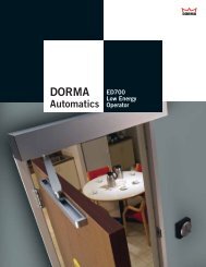
DORMA Automatics, Inc. Series ED-700 (Surface Applied) LOW<br />
ENERGY OPERATING SYSTEM FOR SWINGING DOORS<br />
1.01 SUMMARY:<br />
A. Section Includes: Furnish and install low energy operating system for swinging<br />
door(s) in accordance with plans and specifications.<br />
B. Related Work:<br />
1. Section 07900 - Caulking<br />
2. Section 08400 - Entrances and Storefronts<br />
3. Section 08710 - Finish Hardware<br />
4. Section 08800 – Glass & Glazing<br />
5. Section 16120 - Electrical Supply and Termination<br />
1.02 REFERENCES:<br />
A. ETL/SEMKO (ETL), 70 Codman Hill Road, Boxborough, MA 01719; 800-967-<br />
5352,Fax: 800-813-9442333<br />
B. American National Standards Institute (ANSI), 11 W. 42nd St., 13th Floor, New York,<br />
NY 10036; 212-642-4900, Fax: 212-398-0023.<br />
C. Builders’ Hardware Manufacturers Association (BHMA), 355 Lexington Ave., New<br />
York, NY 10017; 212-661-4261, Fax: 212-370-9047.<br />
D. National Fire Protection Association (NFPA), 1 Batterymarch Park, Quincy,<br />
MA02269, 800-344-3555; 617-770-3000, Fax: 617-984-7057.<br />
E. American Association of Automatic <strong>Door</strong> Manufacturers (AAADM), 1300 Sumner<br />
Avenue, Cleveland, OH 44115-2851; 216-241-7333, Fax: 216-241-0105.<br />
1.03 SUBMITTALS:<br />
A. Product Data: Submit manufacturer’s product data, standard details and installation<br />
instructions for all materials provided in this specification.<br />
B. Shop Drawings: Submit shop drawings that document: profiles, joining methods,<br />
product components, anchorage details, adjacent construction interface, dimensions and<br />
necessary wiring and electrical requirements.<br />
C. Samples: Reasonably sized to adequately represent materials and finishes.<br />
ED700 Specification 9-13-05 1
DORMA Automatics, Inc.<br />
924 Sherwood Drive<br />
Lake Bluff, Illinois 60044<br />
U.S.A. Toll Free:1-877-367-6211<br />
Fax: 1-877-423-7999<br />
http://www.dorma-usa.com<br />
1.04 QUALITY ASSURANCE:<br />
A. Automatic operating system for swinging door(s) shall be certified by the<br />
manufacturer to meet performance design criteria according to the following test<br />
standards: [select, if applicable]:<br />
1. ANSI / BHMA A156.19.<br />
2. ETL Listed / UL 325.<br />
4. CUL/ETL Certified (equivalent to CSA certified).<br />
1.05 WARRANTY/GUARANTEE:<br />
A. Manufacturer’s Standard Warranty: Warranted materials shall be free of defects in material<br />
and workmanship for a period of one year from date of installation.<br />
2.01 MANUFACTURER:<br />
A. DORMA Automatics, Inc.<br />
924 Sherwood Drive<br />
Lake Bluff, Illinois 60044<br />
U.S.A. Toll Free: 1-877-367-6211<br />
Fax: 1-877-423-7999<br />
Internet address: http://www.dorma-usa.com<br />
E-Mail address: automatics@dorma-usa.com<br />
2.02 LOW ENERGY OPERATING SYSTEM FOR SWINGING DOOR(S):<br />
A. Operating System: Shall be DORMA ED-700. The system shall consist of electromechanical<br />
low energy swing door operator enclosed in an aluminum header – 5.5”W x 5”H x length required<br />
or 30” minimum, (139.7 mm x 127 mm x required length or 762 mm), connecting hardware,<br />
actuating controls, and On-Off-Hold Open switch. The operator will allow both manual opening of<br />
the door, and/or provide controlled power opening of the door in response to an input signal.<br />
Additionally, it will offer controlled closing of the door at all times – with or without 120VAC<br />
power. The system shall be completely engineered and manufactured by DORMA Automatics,<br />
Inc. All operator components shall be factory assembled, fully adjusted and tested. The system<br />
shall be installed and adjusted in accordance with ANSI A156.19.<br />
B. <strong>Door</strong> Operation: The ED-700 will provide one or more of the following door operations:<br />
Manual Operation: The force required (to overcome) the mechanics of the motor/gear<br />
drive and the closing spring shall be field adjustable from a minimum of 5lbf. (21N) to<br />
maximum 15 lbf. (67N). Note: The closing force will vary with this adjustment. When<br />
the operator does not have 120 VAC power, it will physically operate in a manual mode.<br />
ED700 Specification 9-13-05 2
DORMA Automatics, Inc.<br />
924 Sherwood Drive<br />
Lake Bluff, Illinois 60044<br />
U.S.A. Toll Free:1-877-367-6211<br />
Fax: 1-877-423-7999<br />
http://www.dorma-usa.com<br />
Powered Operation: When an input signal is applied to the actuating input, the operator<br />
will initiate powered opening of the door - accelerate to an open speed - at the open<br />
check point decelerate the open speed to the open check speed - then change from<br />
open check speed to final open speed as the operator rotation is stopped by the<br />
internal hard stop.<br />
The unit will remain in this position until all actuating input signals have cleared and<br />
time delay(s) have expired - then will begin closing under spring power at closing speed -<br />
and at the close checkpoint reduce the closing speed to close check speed. Optional<br />
“Power Assist Close,” available as an add-on module, will apply motor power to assist<br />
spring closing. Closing force will not exceed 15 lbf. (67N).<br />
In both modes of operation, the final 10° of door closing shall not occur in<br />
less than 1.5 seconds.<br />
The operator control will be an existing analog unit readily available from a reliable and<br />
experienced control board manufacturer. The operator will power open the door in<br />
response to a slight initial manual movement of the door, followed by automatic controlled<br />
spring closing; Knowing-act Opening – a push plate, pushbutton, key switch or similar<br />
switch is actuated and the operator power opens the door, followed by automatic<br />
controlled spring closing; Automatic Opening – a non-contact sensor (motion detector,<br />
etc.) will detect an approaching pedestrian and will automatically open the door, followed<br />
by automatic controlled spring closing.<br />
Opening force, Open speed, Back Check speed, Closing speed, and time delay shall be<br />
individually adjustable within ANSI / BHMA A156.19 requirements.<br />
C. Aluminum Extrusion Finish: Standard anodized finish shall be [select one: 204-R1Class-II<br />
Clear anodize or 313-R1 Class-I Dark Bronze anodize]. [Special anodic finishes, special paint<br />
finishes and metal clad finishes are available upon request. Specify type and color of each finish<br />
desired].<br />
2.03 Component Descriptions:<br />
A. Motor/Gear Drive with Closing Spring and Open Stop:<br />
The motor will be a 90VDC permanent magnet unit connected to a gear reduction assembly<br />
with an output shaft capable of 240° of total rotation. At the end of rotation an operator<br />
mounted stop is provided to determine the full open position of the operator and door. The<br />
stop shall be capable of withstanding reasonable abuse during normal operation. A closing<br />
spring is included in the assembly to return the operator from the full open position to the at<br />
rest or door closed position.<br />
B. Control:<br />
ED700 Specification 9-13-05 3
DORMA Automatics, Inc.<br />
924 Sherwood Drive<br />
Lake Bluff, Illinois 60044<br />
U.S.A. Toll Free:1-877-367-6211<br />
Fax: 1-877-423-7999<br />
http://www.dorma-usa.com<br />
At a minimum, the operator control shall include the following inputs:<br />
a. Actuate: will initiate [subject to other inputs] an opening cycle of the operator,<br />
and will initiate a time delay to begin upon the input signal releasing. This<br />
input is always active, again subject to other inputs.<br />
b. Presence Sensor: Will either:<br />
• Inhibit the operator opening if it is closed, or<br />
• Hold the operator open if it is fully open. This input is ignored while the<br />
operator is in close speed, and for a time delay, adjusted on the<br />
control, thereafter.<br />
• Provides data line output for industry standard dual-zone presence<br />
sensors.<br />
c. Swing Sensor: is enabled when the operator is in open speed, and if triggered<br />
during this mode, will cause the operator to: a.) Stop and resume opening<br />
when sensor clears; or b.) Stop and seek full open at a reduced speed. It is<br />
not active when the door is in open check speed.<br />
d. ON/OFF/HOLD OPEN Switch: to enable either automatic operation of the<br />
operator, and/or, open the operator to full open and remain continuously until<br />
the switch status is changed.<br />
e. LED indicators shall be provided adjacent to each of the above inputs,<br />
indicating status. The following inputs will not require indicators.<br />
• Operator Position Switch: A switch mounted in the operator used to<br />
indicate a defined door position. For the analog control, this switch will be<br />
at the open checkpoint, and a second switch will be required at the close<br />
checkpoint. The switches will be field adjustable.<br />
f. Internally, the control shall be capable of sensing and responding to the<br />
following:<br />
• Push-and-Go: The operator has been manually pushed in the open<br />
direction<br />
• Opening Obstacle: The operator has been inhibited during powered<br />
opening<br />
• Closing Obstacle: The operator has been inhibited during closing<br />
g. Additionally, the control shall provide some convenient method for<br />
enabling/disabling the above sensing modes.<br />
ED700 Specification 9-13-05 4
DORMA Automatics, Inc.<br />
924 Sherwood Drive<br />
Lake Bluff, Illinois 60044<br />
U.S.A. Toll Free:1-877-367-6211<br />
Fax: 1-877-423-7999<br />
http://www.dorma-usa.com<br />
h. All of the inputs shall be configured such that two controls may be connected<br />
in parallel with any or all of the inputs, and proper functionality shall continue.<br />
The control shall provide the following outputs:<br />
• +24VDC: to provide limited power for auxiliary equipment (sensors, locks,<br />
etc.); 2A max.<br />
• Motor: to either provide voltage to power the motor, or to shunt motorgenerated<br />
voltage<br />
• Lock Relay Driver: to control automatic locking, including time delay<br />
between unlock and door opening.<br />
• Signal: to indicate door is open (used for door status and sensor dual-zone<br />
control).<br />
i. At a minimum, the operator control shall provide the following adjustments:<br />
1. Acceleration: The ramp rate of motor voltage (increasing) applied when<br />
initiating an open cycle, whether from full closed or from partially closed<br />
(recycle).<br />
2. Open Speed: The motor voltage applied during the open cycle.<br />
3. Open Force: The motor current applied during the open cycle.<br />
4. Deceleration: The ramp rate of motor voltage (decreasing) when changing<br />
from open speed to open check speed.<br />
5. Open Check Speed: The motor voltage applied during the open cycle<br />
after the checkpoint has been reached, and before the full open position.<br />
6. Final Speed: The motor voltage applied as the operator reaches the full<br />
open position, and remains applied until the close cycle has been initiated.<br />
7. Close Speed: The shunting of the motor-generated voltage during the<br />
closing cycle.<br />
8. Sensor Time Delay: The length of time the door remains open in<br />
response to an Actuate Sensor signal, and after all inputs have been<br />
cleared.<br />
9. Lock Out Time Delay: An adjustable length of time, during door closing,<br />
that the presence sensor input is disabled.<br />
10. Lock Delay: The length of time between receipt of an actuating signal and<br />
the initiation of operator open speed. Note: The Lock/Vestibule output<br />
status is changed immediately upon receipt of the actuating signal.<br />
ED700 Specification 9-13-05 5
DORMA Automatics, Inc.<br />
924 Sherwood Drive<br />
Lake Bluff, Illinois 60044<br />
U.S.A. Toll Free:1-877-367-6211<br />
Fax: 1-877-423-7999<br />
http://www.dorma-usa.com<br />
11. Open Obstruction: The threshold force required to inhibit the opening<br />
cycle before the control responds by reducing the open speed.<br />
12. Close Obstruction: The threshold speed, during closing, required to<br />
initiate a re-open cycle.<br />
j. Traditional potentiometers will be used for the specified control adjustments,<br />
for a total of nine (9) individual single-turn potentiometers. Small switches will<br />
be used for “Push-and-Go,” “Close Obstruction” and “Lock Delay.”<br />
The Potentiometer functions follow:<br />
1. Acceleration: Open acceleration adjustment. Sets motor acceleration to<br />
open speed setting.<br />
2. Deceleration: Open deceleration adjustment. Determines how quickly<br />
the door slows after the open check switch is activated.<br />
3. Speed: Open speed adjustment. Sets the open speed of the operator<br />
from start to open check.<br />
4. Check: Open speed check adjustment. Sets the speed after the open<br />
check switch falls onto the cam flat (approximately 80°).<br />
5. Hold: Hold voltage function. Control switches to hold-open voltage after a<br />
nominal 12 second delay from activate or immediately after OBST or Stopand-Seek<br />
input.<br />
6. Delay: Time delay adjustment to begin closing after release of activating<br />
switches (1-30 sec).<br />
7. Lock Out: Lock out time delay. Sets the length of time to ignore the safety<br />
sensor during door closing.<br />
8. Limit: Torque limiting. Controls the amount of opening force.<br />
9. Obstruction: Sensitivity to an obstruction during opening<br />
On/Off selectable jumper blocks are used for the following functions:<br />
10. Push & Go: A slight push and/or pull on the door in the direction of<br />
opening will initiate a powered open cycle of the operator.<br />
11. T stop: An obstruction during closing speed will initiate a re-open cycle of<br />
the door.<br />
ED700 Specification 9-13-05 6
DORMA Automatics, Inc.<br />
924 Sherwood Drive<br />
Lake Bluff, Illinois 60044<br />
U.S.A. Toll Free:1-877-367-6211<br />
Fax: 1-877-423-7999<br />
http://www.dorma-usa.com<br />
12. Lock Delay Enable: A slight delay is required to allow an automatic lock to<br />
unlock, eliminating any mechanical bind, before the door begins to open.<br />
D. Mounting Base plate and Assembly Enclosure<br />
The components shall be aesthetically acceptable and capable of changing the operator<br />
hand and direction of swing in the field or shop. The completed assembly shall be<br />
capable of withstanding normal exterior installation conditions.<br />
E. <strong>Door</strong> Connecting Hardware and Miscellaneous Installation Hardware<br />
Use of existing DORMA components such as push arms and slide track pull channels will<br />
be used and are compatible with the EDA system.<br />
2.04 OPERATING CONDITIONS:<br />
A. Climatic Conditions: All automatic operating system components shall operate between -5 F<br />
(-20 C) and +120 F (48 C) in all climatic conditions.<br />
2.05 RELATED WORK REQUIREMENTS:<br />
A. Electrical: 120 VAC, 60 Hz, 5 Amp service provided to the header.<br />
3.01 INSPECTION:<br />
A. The installer shall verify that the installation area is dry, clean and free of foreign matter.<br />
Check as-built conditions and verify the manufacturer’s automatic operating system details for<br />
accuracy to fit the frame assembly prior to fabrication. Report [in writing] to the Contractor any<br />
detrimental conditions to the proper functioning of the low energy operating system. Installation<br />
shall proceed once any unsatisfactory conditions have been corrected and in accordance to the<br />
manufacturer’s recommendations.<br />
3.02 INSTALLATION:<br />
A. Installation shall be by an installer approved and trained by the manufacturer in strict<br />
accordance with the manufacturer’s instructions and fire marshal’s listing requirements.<br />
B. Comply with the low energy operating system manufacturer’s recommendations and/or<br />
installation guide when installing the system. Mount units plumb, level and secure.<br />
C. Provide all fasteners required for installation of the low energy operating system.<br />
D. Adjustment and Cleaning: After repeated operation of the completed installation, inspect door<br />
operators and controls for optimum operating condition and safety. Clean all metal surfaces<br />
promptly after installation.<br />
E. Explain and review the Owner's Manual.<br />
ED700 Specification 9-13-05 7