
Create successful ePaper yourself
Turn your PDF publications into a flip-book with our unique Google optimized e-Paper software.
www.collegehillshonda.com<br />
INSTALLATION<br />
INSTRUCTIONS<br />
Accessory<br />
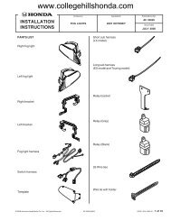
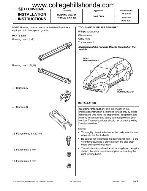
RUNNING BOARD<br />
P/N08L33-SWA-100<br />
Application<br />
<strong>2008</strong> CR-V<br />
Publications No.<br />
AII 37530<br />
Issue Date<br />
AUG 2007<br />
NOTE: Running boards cannot be installed if vehicle is<br />
equipped with front splash guards.<br />
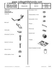
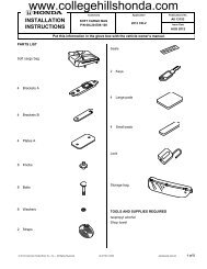
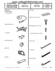
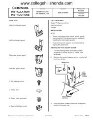
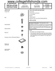
PARTS LIST<br />
Running board (Left)<br />
TOOLS AND SUPPLIES REQUIRED<br />
Phillips screwdriver<br />
Clip remover<br />
Utility knife<br />
Torque wrench<br />
Illustration of the Running Boards Installed on the<br />
Vehicle<br />
RIGHT<br />
RUNNING BOARD<br />
Running board (Right)<br />
4 Brackets A<br />
LEFT<br />
RUNNING BOARD<br />
6227011Y<br />
INSTALLATION<br />
4 Brackets B<br />
32 Flange bolts, 8 x 20 mm<br />
16 Flange nuts, 6 mm<br />
Customer Information: The information in this<br />
installation instruction is intended for use only by skilled<br />
technicians who have the proper tools, equipment, and<br />
training to correctly and safely add equipment to your<br />
vehicle. These procedures should not be attempted by<br />
“do-it-yourselfers.”<br />
NOTE:<br />
• Thoroughly clean the bottom of the body from the rear<br />
wheels to the front wheels.<br />
• Be careful not to damage the body paint finish. To prevent<br />
damage, place a blanket under the side step<br />
board during the installation.<br />
• These instructions show the left running board being installed;<br />
the same procedure applies to installing the<br />
right running board.<br />
16 Flange nuts, 8 mm<br />
© 2007 American <strong>Honda</strong> Motor Co., Inc. – All Rights Reserved AII 37530 (0708) 08L33-SWA-1000-91 1 of 6
www.collegehillshonda.com<br />
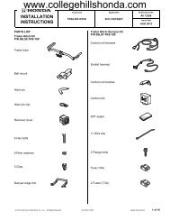
1. Turn the steering wheel all the way counterclockwise.<br />
4. Remove the four clips under the left side sill panel.<br />
LEFT FRONT<br />
INNER FENDER<br />
LEFT SIDE SILL<br />
PANEL<br />
4 CLIPS<br />
4 SELF-TAPPING<br />
SCREWS<br />
(Reuse.)<br />
6227021Y<br />
2. Remove and retain the four self-tapping screws from<br />
the left front inner fender.<br />
3. Remove and retain the two self-tapping screws from<br />
the left rear inner fender.<br />
5. Pull out on the front of the left rear wheel arch<br />
protector to release the clip.<br />
VEHICLE PANEL<br />
LEFT SIDE SILL<br />
PANEL<br />
6227040Y<br />
LEFT REAR WHEEL ARCH<br />
PROTECTOR (Move away.)<br />
LEFT REAR<br />
INNER FENDER<br />
CLIP<br />
(Release.)<br />
7 CLIPS<br />
CLIP<br />
(Reuse.)<br />
FRONT<br />
2 SELF-TAPPING<br />
SCREWS<br />
(Reuse.)<br />
6227030Y<br />
CLIP<br />
(Reuse.)<br />
VEHICLE<br />
BODY<br />
LEFT SIDE SILL<br />
PANEL<br />
4 CLIPS<br />
6707040E<br />
6. With the left rear wheel arch protector pulled away<br />
from the side sill trim, pull the left side sill trim forward<br />
to release the five retaining tabs and two clips.<br />
Remove the left side sill trim.<br />
7. Remove three side sill trim clips, two at the front and<br />
one at the rear.<br />
2 of 6 AII 37530 (0708) © 2007 American <strong>Honda</strong> Motor Co., Inc. – All Rights Reserved
www.collegehillshonda.com<br />
8. Remove the left undercover from under the vehicle<br />
(four clips and three bolts).<br />
LEFT SIDE<br />
LEFT UNDERCOVER<br />
2 CLIPS<br />
10. Using a utility knife, cut out the left undercover along<br />
the mark on the inner side of the undercover.<br />
Remove any burrs.<br />
LEFT SIDE<br />
UTILITY KNIFE<br />
CUTOUT<br />
Pull down.<br />
FRONT<br />
LEFT UNDERCOVER<br />
MARK<br />
LEFT UNDERCOVER<br />
FRONT<br />
2 CLIPS<br />
3 BOLTS<br />
9. Remove the right undercover the same way.<br />
11. Cut out the right undercover the same way.<br />
RIGHT SIDE<br />
RIGHT UNDERCOVER<br />
2 CLIPS<br />
FRONT<br />
MARK<br />
UTILITY KNIFE<br />
RIGHT SIDE<br />
CUTOUT<br />
Pull down.<br />
RIGHT UNDERCOVER<br />
RIGHT UNDERCOVER<br />
4 CLIPS<br />
3 BOLTS<br />
FRONT<br />
© 2007 American <strong>Honda</strong> Motor Co., Inc. – All Rights Reserved AII 37530 (0708) 3 of 6
www.collegehillshonda.com<br />
12. Remove the bracket from the left side sill panel (two<br />
self-tapping screws).<br />
14. Remove the two spring nuts and three clips from the<br />
left side sill panel and install them on the left running<br />
board in the areas shown.<br />
FRONT<br />
LEFT SIDE SILL<br />
PANEL<br />
SPRING NUT (Reuse.)<br />
LEFT RUNNING<br />
BOARD<br />
BRACKET<br />
LEFT<br />
RUNNING<br />
BOARD<br />
SELF-TAPPING SCREW<br />
(Reuse.)<br />
6227060Y<br />
13. Install the bracket to the left running board with one<br />
of the screws removed in the above step.<br />
BRACKET<br />
FRONT<br />
LEFT RUNNING<br />
BOARD<br />
3 CLIPS<br />
(Removed in step 7.)<br />
6227080Y<br />
15. Install the three clips (removed in step 7) into position<br />
on the left running board.<br />
16. Position the two brackets A on the left running board<br />
by aligning the holes in brackets A with the bolts on<br />
the running board. Secure brackets A with the eight<br />
6 mm flange nuts, but don’t tighten them at this time.<br />
BRACKET<br />
A<br />
8 FLANGE NUTS<br />
(6 mm)<br />
LEFT<br />
RUNNING<br />
BOARD<br />
8 FLANGE NUTS<br />
(6 mm)<br />
SELF-TAPPING SCREWS<br />
(Reuse.)<br />
BRACKET A<br />
LEFT<br />
RUNNING<br />
BOARD BOLT<br />
BRACKET A<br />
LEFT<br />
RUNNING<br />
BOARD BOLT<br />
6227111Y<br />
4 of 6 AII 37530 (0708) © 2007 American <strong>Honda</strong> Motor Co., Inc. – All Rights Reserved
www.collegehillshonda.com<br />
17. Position the left running board on the vehicle, and<br />
secure brackets A using four flange bolts. Make sure<br />
the inner fender fits on the inside of the left running<br />
board end cap. Align the clips installed in step 15 to<br />
the holes in the body panel, and push them into position.<br />
19. Secure brackets A and B using eight flange bolts and<br />
eight 8 mm flange nuts.<br />
Front bracket: Assemble by aligning the hole in<br />
bracket B with the lower hole in bracket A.<br />
Rear bracket: Assemble by aligning the hole in<br />
bracket B with the upper hole in bracket A.<br />
BRACKET A<br />
FRONT<br />
REAR<br />
LEFT<br />
RUNNING<br />
BOARD<br />
END CAP<br />
INNER<br />
FENDER<br />
8 FLANGE<br />
BOLTS<br />
BRACKET A<br />
FRONT<br />
LEFT<br />
RUNNING<br />
BOARD<br />
BRACKET A<br />
CLIP<br />
BRACKET A<br />
4 FLANGE<br />
BOLTS<br />
CLIP<br />
BRACKET A<br />
6227122Y<br />
18. Install each bracket B into position on the vehicle,<br />
and secure each bracket with two flange bolts.<br />
BRACKET B<br />
8 FLANGE NUTS<br />
(8 mm)<br />
6825020B<br />
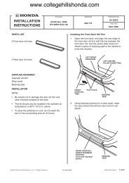
20. Gently pull out on the fender arch to release the clip<br />
and install the front of the left running board under<br />
the inner front fender using the four self-tapping<br />
screws removed in step 2.<br />
LEFT FRONT<br />
INNER FENDER<br />
FENDER ARCH<br />
(Pull out.)<br />
LEFT RUNNING<br />
BOARD<br />
BRACKET B<br />
FRONT<br />
Install under the inner<br />
left front fender.<br />
4 SELF-TAPPING SCREWS<br />
(Removed in step 2.) 6227151Y<br />
FLANGE<br />
BOLTS<br />
FLANGE BOLTS<br />
BRACKET B<br />
6825010B<br />
© 2007 American <strong>Honda</strong> Motor Co., Inc. – All Rights Reserved AII 37530 (0708) 5 of 6
www.collegehillshonda.com<br />
21. Attach the left rear fender arch molding to the<br />
running board. Secure the running board using the<br />
two self-tapping screws removed in step 3.<br />
LEFT REAR<br />
FENDER<br />
COVER<br />
LEFT REAR<br />
INNER<br />
FENDER<br />
LEFT RUNNING<br />
BOARD<br />
SELF-TAPPING SCREWS<br />
(Removed in step 3.)<br />
6227161Y<br />
22. Repeat steps 1 thru 21 to install the right running<br />
board on the right side of the vehicle.<br />
23. Reinstall the undercovers.<br />
6 of 6 AII 37530 (0708) © 2007 American <strong>Honda</strong> Motor Co., Inc. – All Rights Reserved