Air Springs RUBENA
Air Springs RUBENA
Air Springs RUBENA

Create successful ePaper yourself
Turn your PDF publications into a flip-book with our unique Google optimized e-Paper software.
KATALOGUE SHEET<br />
<strong>RUBENA</strong> Type <strong>Air</strong> <strong>Springs</strong><br />
The air springs are generally intended for many different applications<br />
where is necessary to eliminate the vibration and beats. For example<br />
they may be used for the resilient mounting of bus or truck driver seats,<br />
trucks, trolley-buses, tractors, railway-carriage, tramway waggons and<br />
car axles, etc. They are used for suspension the resilient mounting of<br />
heavy machines, shock-creating and vibrating devices (such as forging<br />
presses, power hammers, textile looms, etc.). They are suitable for<br />
insulating laboratory devices from vibrations. They are also<br />
recommended for the resilient mounting of trailers. Other applications<br />
should be discussed with the manufacturer.<br />
Using the air springs in vehicles is advantageous in many ways, e.g.<br />
slower tyre wear and tear, lower fuel consumption, sparing the vehicles.<br />
The air-spring pressure control function facilitates reaching the optimum height of the vehicle and<br />
thus the correct functioning of vehicle lights. Resilient-mounted seats in trucks and tractors increase<br />
drivers’ comfort. The negligible maintenance cost and longer durability make using air springs<br />
preferable in comparison with normal springs.<br />
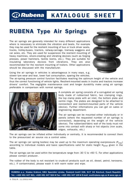
A complete air spring consists of a corrugated air spring<br />
body made of rubberized fabric, two clamping rings,<br />
the top clamp plate with air inlet, the bottom plate and<br />
centre rings. The plates are designed to be attached to<br />
nonresilient and resilient-mounted parts of the vehicle<br />
(device). Further informations you can get on sales or<br />
engineering department.<br />
The air springs can be mounted either individually or in<br />
panels (where the requested number of air springs is<br />
connected), depending on the weight of the vehicle<br />
(device). The rubberized-fabric wall of the body must not<br />
come into contact with sharp or hot objects (iron scale,<br />
edges, exhausts, etc.)<br />
The air springs can be inflated either individually or centrally. It is recommended to connect them<br />
to the pressurized air source via a control valve.<br />
The air springs (air spring bodies) may be used up to the maximum operating overpressure (P max )<br />
according to individual models and basic specifications valid for static height H STAT given in the<br />
table.<br />
The air springs can be used within the temperature range from -30 °C to +60 °C. For other applications<br />
please contact producer.<br />
The rubber of the body is not resistant to crude-oil products such as oil, diesel, petrol, kerosene,<br />
etc.). If contaminated, please wash it with warm water and wipe.<br />
<strong>RUBENA</strong> a.s. Hradec Králové, SBU Speciální výroba, Èeských bratøí 338, 547 36 Náchod, Czech Republic<br />
Tel.: +420 491 447 521, +420 491 447 524 ● Fax: +420 491 447 109 ● E-mail: avs@rubena.cgs.cz ● www.cgs.cz<br />
© ÈGS/R: 11/2003/XXXI
BASIC SPECIFICATIONS<br />
<strong>Air</strong> Spring<br />
A/Number of<br />
convolutions<br />
A max.<br />
[mm]<br />
130/1 140 80 53,6 75 ± 30 638 74 0.5 0.3<br />
130/2 140 145 53,6 130 ± 40 1 155 73 0.5 0.4<br />
130/3 140 210 53,6 170 ± 60 1 515 77 0.5 0.5<br />
170/1 180 92 90 80 ± 30 960 152 0.7 0.4<br />
170/2 180 162 90 135 ± 60 1 945 154 0.7 0.6<br />
170/3 180 232 90 180 ± 100 2 760 156 0.7 0.9<br />
190/1 200 140 96 130 ± 30 2 410 154 0.5 0.5<br />
² 190/2 200 210 96 200 ± 60 3 640 153 0.5 0.8<br />
190/3 200 280 96 240 ± 100 4 935 155 0.7 1.1<br />
280/1 295 108 150 100 ± 30 4 480 385 0.7 2.1<br />
280/2 295 179 150 165 ± 60 6 720 387 0.7 2.6<br />
² 280/3 295 250 150 230 ± 100 8 970 389 0.7 3.2<br />
290/1 310 93 154 115 ± 60 4 300 342 0.7 2.2<br />
² 290/2 310 162 154 175 ± 90 7 315 400 0.7 2.8<br />
² 290/3 310 231 154 240 ± 100 10 150 438 0.7 3.4<br />
² 340/2 345 162 192 170 ± 90 9 500 600 0.7 1.8<br />
ª 34/3 345 231 192 240 ± 100 14 900 600 0.7 2.4<br />
380/1 395 106 234 110 ± 30 7 300 714 0.7 2.2<br />
380/2 395 175 234 170 ± 75 12 900 739 0.7 3.0<br />
ª 38/3 395 244 234 240 ± 100 19 650 756 0.7 3.7<br />
410/1 410 130 270 130 ± 30 11 000 973 0.7 2.4<br />
² 410/2 410 206 270 205 ± 75 18 000 975 0.7 3.4<br />
² 410/3 410 280 270 280 ± 120 26 700 1 000 0.7 4.3<br />
Legend:<br />
A = outside diameter of the bellow (in mm)<br />
Amax. = max outside diameter of the bellow at Hstat. and Pmax. B = bellow high in the mould<br />
C = inside diameter at the bellow in the mould<br />
Hstat = static (assembling) height of the bellow<br />
Z = stroke of the bellow from Hstat. V = volume of the bellow at H stat.<br />
S ef. = effective area of the bellow at H stat.<br />
Pmax. = max operating overpressure at Hstat. ª – outside diameter of the bellow (in cm)<br />
² – job- order manufacture<br />
B C Hstat. Z V Sef. Pmax. m<br />
[mm] [mm] [mm] [cm3] [cm [PMa] [kg]<br />
2]<br />
[mm]