'82-'01 Camaro/ Firebird/TransAm - Air Lift
'82-'01 Camaro/ Firebird/TransAm - Air Lift
'82-'01 Camaro/ Firebird/TransAm - Air Lift

Create successful ePaper yourself
Turn your PDF publications into a flip-book with our unique Google optimized e-Paper software.
EASYSTREET<br />
‘82-’01 <strong>Camaro</strong>/<br />
<strong>Firebird</strong>/<strong>TransAm</strong><br />
Rear Kit No. 75616<br />
www.airliftcompany.com<br />
Please read these instructions completely before proceeding with installation.<br />
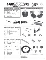
Installation Components<br />
Item P/N Description Quantity<br />
A 58571 <strong>Air</strong> Springs 2<br />
B 07937 Upper Bracket 2<br />
C 03938 Lower Bracket 2<br />
D 21854 1/8” NPT x 3/8” Tube Elbow 2<br />
E 17139 1 /2"-13 x 1" Bolt 2<br />
F 18429 1 /2" Lock Washer 2<br />
G 18414 1 /2" Flat Washer 2<br />
H 18454 3 /4" Nylon Hex Nut 2<br />
I 10750 Retaining Strap 2<br />
J 17102 Self Tapping Bolt 6<br />
K 17103 5 /16"-18 x 1 Bolt 2<br />
L 18438 5<br />
/16" Lock Nut 2<br />
M 09484 Thermal Sleeve 1<br />
N 10613 Heat Shield 1<br />
O 10741 Heat Shield Clamp 2<br />
Warranty Information<br />
1. All goods come with a one year manufacturer’s<br />
warranty against defects.<br />
2. Warranty will be void if the kit is altered for any<br />
reason and/or adapted to applications other than<br />
those suggested.<br />
3. Any abrasions or rub marks on the air spring<br />
portion of the kit will not be covered under<br />
warranty. The customer is responsible for all<br />
repair charges.<br />
4. Driving at a low PSI can cause the air spring to<br />
bottom out. Repeated bottoming out can cause<br />
the air spring to fail. Failure resulting from<br />
repeated bottoming out is not covered under<br />
warranty.<br />
5. The customer is responsible for all shipping costs<br />
to <strong>Air</strong> <strong>Lift</strong> Company for all warranty claims.<br />
6. Please call tech support at 1-800-248-0892<br />
before shipping a product to <strong>Air</strong> <strong>Lift</strong> Company.<br />
Technical Support<br />
1-800-248-0892<br />
B<br />
A<br />
C<br />
J<br />
I<br />
L<br />
D<br />
H<br />
Figure 1<br />
G<br />
F<br />
E<br />
K<br />
J<br />
MN-484<br />
(04409)<br />
ECN 4765<br />
1
2<br />
Figure 2<br />
II. Installing the <strong>Air</strong> Springs<br />
1. Assemble the springs as illustrated in Figures 1 and 2.<br />
I. Preparing the Vehicle<br />
1. With the car on a flat surface and the tires inflated to the<br />
manufacturers recommendations, take the height<br />
measurements from the center of the wheel to the bottom<br />
edge of the fenderwell and record them below. This is the<br />
Normal Ride Hieght.<br />
Driver Side: ______ Passenger Side: ______<br />
2. Raise the vehicle on a hoist or place on jack stands so<br />
that the suspension can be completely loose. Be sure to<br />
abide to all safety practices when working under the<br />
vehicle.<br />
3. Remove the wheels.<br />
4. Disconnct the rear lower shock mounts so that the<br />
suspension can be completely extended.<br />
5. Drop the axle and carefully remove the rear coil springs<br />
one at a time. Also remove the rubber isolators.<br />
a. Place the upper bracket (B) onto the air spring (A). Install the air fitting (D) finger tight plus 1 1 /2 turns,<br />
being careful to tighten on the metal hex nut only.<br />
b. Attach the upper bracket to the air spring by installing the nylon nut (H) over the air fitting onto the<br />
threaded post. Tighten to 4 ft-lbs.<br />
c. Install the lower bracket (C) and retaining strap (I) to the bottom of the air spring assembly and secure<br />
with a 1 /2" bolt (E), lock washer (F), and flat washer (G). Leave loose for adjustment.<br />
2. Place the air spring assembly over the upper spring seat with the single “leg” of the upper bracket facing<br />
forward. Nest the lower cup around the lower spring seat assembly with the retaining strap tab facing<br />
foward on the passenger side and indexed into the slot on the driver side (Figure 1).<br />
3. Remove the entire assembly and tighten the lower mount with the anit-rotation tabs in the proper position.<br />
Tighten the lower bolt to 10 ft-lbs. Reinstall the air spring assembly onto the vehicle.<br />
4. Raise the axle so that the upper bracket contacts the body around the spring seat and inflate to 10 p.s.i.<br />
Continue raising the axle back up to the previously recorded ride hieght.<br />
Technical Support<br />
1-800-248-0892
5. Align the air spring by moving the upper bracket. The air spring needs to be centered and in line with the<br />
lower bracket.<br />
6. Using the upper bracket as a template, drill a 1 /4" hole for the forward leg of the mount and secure with one<br />
5 /16" self tapping bolt (J). Do not over tighten. Install the other two self tapping bolts in the same manner.<br />
6. Install the 5 /16" x 1" bolt (K) through the anit-rotation tabs with the nut (L) on the outside of the tab. Tighten<br />
securely.<br />
7. Repeat installation procedure for the remaining side.<br />
8. Reconnect the shocks.<br />
III. Installing the Heat Shield<br />
CAUTION: To prevent air line from melting, keep it at least<br />
12" from the exhaust system.<br />
1. The exhaust pipe usually runs very close to the air spring/<br />
air line on the passenger side. Install the provided heat<br />
shield onto the exhaust pipe as shown in Figure 3.<br />
Technical Support<br />
1-800-248-0892<br />
"Dead air space" Exhaust Pipe<br />
Figure 3<br />
Bend tabs<br />
on heat shield.<br />
3
IV. Maintenance and Operations<br />
By following these steps, vehicle owners will obtain the longest life and best results from their air springs.<br />
4<br />
Minimum <strong>Air</strong> Pressure<br />
Maximum <strong>Air</strong> Pressure<br />
10 p.s.i. 100 p.s.i.<br />
Failure to maintain correct minimum pressure (or pressure proportional to load), bottoming<br />
out, over-extension, or rubbing against another component will void the warranty.<br />
1. Always maintain Normal Ride Height. Never inflate beyond 100 p.s.i.<br />
2. When increasing load, always adjust the air pressure to maintain the Normal Ride Height. Increase or decrease<br />
pressure from the system as necessary to attain Normal Ride Height for optimal ride and handling. Remember that<br />
loads carried behind the axle (including tongue loads) require more leveling force (pressure) than those carried<br />
directly over the axle.<br />
3. IMPORTANT: For your safety and to prevent possible damage to your vehicle, do not exceed maximum Gross<br />
Vehicle Weight Rating (GVWR), as indicated by the vehicle manufacturer. Although your air springs are rated at a<br />
maximum inflation pressure of 100 p.s.i. The air pressure actually needed is dependant on your load and GVWR,<br />
which may be less than 100 p.s.i. Check your vehicle owners manual and do not exceed the maximum load listed<br />
for your vehicle.<br />
4. Should it become necessary to raise the vehicle by the frame or do any service work, make sure the system is at<br />
minimum pressure (10 p.s.i.) for safety and to reduce the tension on the suspension/brake components.<br />
EASYSTREET<br />
Thank you for purchasing <strong>Air</strong> <strong>Lift</strong> Products<br />
Mailing Address: Street Address:<br />
AIR LIFT COMPANY AIR LIFT COMPANY<br />
P.O. Box 80167 2727 Snow Rd.<br />
Lansing, MI 48908-0167 Lansing, MI 48917<br />
Local Phone: (517) 322-2144<br />
Fax: (517) 322-0240<br />
http://www.airliftcompany.com<br />
For Technical Assistance call 1-800-248-0892<br />
Technical Support<br />
“The Choice of the 1-800-248-0892 Professional Installer”