
Create successful ePaper yourself
Turn your PDF publications into a flip-book with our unique Google optimized e-Paper software.
Table of Contents<br />
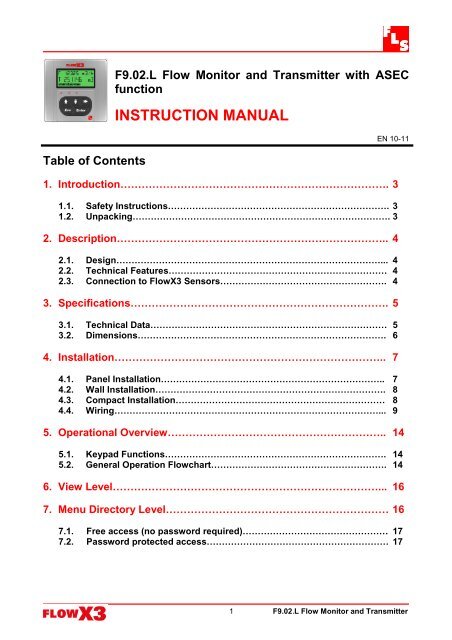
<strong>F9.02.L</strong> Flow Monitor and Transmitter with ASEC<br />
function<br />
INSTRUCTION MANUAL<br />
EN 10-11<br />
1. Introduction…………………………………………………………………. 3<br />
1.1. Safety Instructions………………………………………………………………. 3<br />
1.2. Unpacking…………………………………………………………………………. 3<br />
2. Description………………………………………………………………….. 4<br />
2.1. Design……………………………………………………………………………... 4<br />
2.2. Technical Features……………………………………………………………… 4<br />
2.3. Connection to FlowX3 Sensors………………………………………………. 4<br />
3. Specifications………………………………………………………………. 5<br />
3.1. Technical Data…………………………………………………………………… 5<br />
3.2. Dimensions………………………………………………………………………. 6<br />
4. Installation………………………………………………………………….. 7<br />
4.1. Panel Installation……………………………………………………………….. 7<br />
4.2. Wall Installation…………………………………………………………………. 8<br />
4.3. Compact Installation…………………………………………………………… 8<br />
4.4. Wiring……………………………………………………………………………... 9<br />
5. Operational Overview…………………………………………………….. 14<br />
5.1. Keypad Functions………………………………………………………………. 14<br />
5.2. General Operation Flowchart…………………………………………………. 14<br />
6. View Level…………………………………………………………………... 16<br />
7. Menu Directory Level……………………………………………………… 16<br />
7.1. Free access (no password required)………………………………………… 17<br />
7.2. Password protected access…………………………………………………… 17<br />
1<br />
<strong>F9.02.L</strong> Flow Monitor and Transmitter
8. Menu and Edit Level………………………………………………………. 18<br />
8.1. Calibration Menu…………………………………………………………………… 18<br />
8.1.1. Unit………………………………………………………………………………. 18<br />
8.1.2. K-Factor…………………………………………………………………………. 19<br />
8.1.3. Material…………………………………………………………………………. 19<br />
8.1.4. Size………………………………………………………………………………. 20<br />
8.2. Output Menu………………………………………………………………………… 20<br />
8.2.1. 4 – 20mA Output……………………………………………………………….. 21<br />
8.2.2. SSR1 Output (OPT)…………………………………………………………… 21<br />
8.2.2.1. SSR1 Output (OPT): MIN mode………..…………………………….… 22<br />
8.2.2.2. SSR1 Output (OPT): MAX mode………….……………………………... 22<br />
8.2.2.3. SSR1 Output (OPT): PULSE mode………..……………………………..23<br />
8.2.2.3. SSR1 Output (OPT): WINDOW mode…..…………………………….. 23<br />
8.2.2.4. SSR1 Output (OPT): FREQUENCY mode……..………………………..24<br />
8.3. Simulation Menu……………………………………………………………………. 25<br />
8.3.1. Test 4 – 20mA Loop……………………………………………………………. 25<br />
8.3.2. Test SSR1 Output ……………………………………………………….. 26<br />
8.4. Options Menu……………………………………………………………………….. 27<br />
8.4.1. Contrast…………………………………………………………………………. 27<br />
8.4.2. Filter……………………………………………………………………………… 28<br />
8.4.3. Backlight………………………………………………………………………… 28<br />
8.4.4. Flow Decimal Point…………………………………………………………….. 29<br />
8.4.5. Total Decimal Point…………………………………………………………….. 29<br />
8.4.6. Loop Adjust 4mA……………………………………………………………….. 30<br />
8.4.7. Loop Adjust 20mA……………………………………………………………… 30<br />
8.4.8. Menu PWD……………………………………………………………………… 31<br />
8.4.9. Restot PWD…………………………………………………………………….. 31<br />
8.4.10. K-Factor Calculate…………………………………………………………… 32<br />
8.4.11. ASEC…………………………………………………………………………… 32<br />
9. Troubleshooting……………………………………………………………. 33<br />
9.1. Display messages………………………………………………………………….. 33<br />
10.Ordering Data………………………………………………………………. 34<br />
2<br />
<strong>F9.02.L</strong> Flow Monitor and Transmitter
1. Introduction<br />
1.1. Safety Instructions<br />
General Statements<br />
<br />
<br />
<br />
<br />
Do not install and service the instrument without following the Instruction<br />
Manual.<br />
This unit is designed to be connected to other instruments which can be<br />
hazardous if used improperly. Read and follow all associated instrument<br />
manuals before using with this instrument.<br />
Unit installation and wiring connections should only be performed by qualified<br />
staff.<br />
Do not modify product construction.<br />
Installation and Commissioning Statements<br />
<br />
<br />
<br />
Remove power to the instrument before wiring input and output connections.<br />
Do not exceed maximum specifications using the instrument.<br />
To clean the unit, use only chemical compatible products.<br />
1.2. Unpacking<br />
Please verify that the product is complete and without any damage. The following<br />
items must be included:<br />
F9.02L Flow Monitor and Transmitter<br />
Instruction Manual for F9.02L Flow Monitor and Transmitter<br />
Instruction Manual for F3.00 Flow Sensor (only for F9.02.XXL Compact Flow<br />
Monitor and Transmitter)<br />
3<br />
<strong>F9.02.L</strong> Flow Monitor and Transmitter
2. Description<br />
2.1. Design<br />
The FLS FlowX3 <strong>F9.02.L</strong> Flow Monitor and Transmitter is designed to convert the<br />
signal from all FlowX3 flow sensors into a display indication and a 4…20 mA signal for<br />
long distance transmission and it also provides one programmable open collector<br />
output and two relay outputs. A very high flexibility is achieved via only one packaging<br />
for compact pipe mount, panel or wall installation. Self explaining calibration menus<br />
allow a customized setup of all measuring parameters and the state of the art<br />
electronic design ensures long-term reliable and stable signals.<br />
2.2. Technical Features<br />
2.3. Connection to FlowX3 Sensors<br />
FlowX3 Sensors<br />
FlowX3<br />
Monitor<br />
F3.00.H<br />
F3.00C<br />
F3.01.H<br />
F3.01.C<br />
F3.10.H<br />
F3.15.H*<br />
F3.30.H*<br />
ULF.H<br />
ULF.R<br />
ULF3.15*<br />
ULF3.30*<br />
F3.80<br />
F111.H<br />
F111.C<br />
F3.60<br />
<strong>F9.02.L</strong> X X X X X<br />
* with Output Kit mounted<br />
4<br />
<strong>F9.02.L</strong> Flow Monitor and Transmitter
3. Specifications<br />
3.1. Technical Data<br />
General<br />
Associated flow sensor:<br />
FLS FlowX3 Hall effect with frequency output<br />
Materials:<br />
Case: PC<br />
Panel gasket: Neoprene<br />
Wall & Field gasket: EPDM<br />
Keypad: 5-button silicone rubber<br />
Display:<br />
3 line LCD: 2 x 12 alphanumeric lines + 1 icon line<br />
Update rate: 1 second<br />
Contrast: User adjustable with 5 levels<br />
Enclosure: IP65 front<br />
Electrical<br />
Supply Voltage: 12 to 24 VDC 10% regulated<br />
Sensor Input (Frequency):<br />
Sensor power: 5 VDC @ < 20 mA<br />
Range: 0.5 to 1000 Hz<br />
Optically isolated from current loop<br />
Short circuit protected<br />
Current output:<br />
4…20 mA, isolated, fully adjustable and reversible<br />
Max loop impedance: 150 @ 12 VDC, 330 @ 18 VDC, 600 @ 24 VDC<br />
Solid State Relay output:<br />
User selectable as MIN alarm, MAX alarm, Pulse Out, Window alarm, Freq Out, Off<br />
Optically isolated, 50 mA MAX sink, 24 VDC MAX pull-up voltage<br />
Max pulse/min: 300<br />
Hysteresis: User selectable<br />
Relay output:<br />
User selectable as MIN alarm, MAX alarm, Pulse Out, Window alarm, Off<br />
Mechanical SPDT contact<br />
Expected mechanical life ( min. operations ): 10 7<br />
Expected electrical life ( min. operations ):<br />
o N.O./N.C. switching capacity 8 A 240 VAC n° of operations 10 x 10 4<br />
Max pulse/min: 60<br />
Hysteresis: User selectable<br />
Environmental<br />
Operating temperature: -10 to +70°C (14 to 158°F)<br />
Storage temperature: -15 to +80°C (5 to 176°F)<br />
Relative humidity: 0 to 95% non condensing<br />
Standards and Approvals<br />
Manufactured under ISO 9002<br />
Manufactured under ISO 14001<br />
CE<br />
5<br />
<strong>F9.02.L</strong> Flow Monitor and Transmitter
3.2. Dimensions<br />
Compact Mount<br />
Panel Mount<br />
Wall Mount<br />
6<br />
<strong>F9.02.L</strong> Flow Monitor and Transmitter
4. Installation<br />
The flow monitor & transmitter is available just in one packaging for compact field version,<br />
panel or wall installation. The compact field version is mounted on top of the sensor using<br />
the compact mounting kit (F9.KC1), the panel version is installed using the panel mounting<br />
kit (F9.KP1), while the wall mounting version is fixed with the wall mounting kit<br />
(F9.KWX).The mounting kits can be ordered directly connected to the monitor or<br />
separately and then simply installed on it.<br />
4.1. Panel Installation<br />
The panel mounting version consists of the monitor and the mounting bracket kit<br />
F9.KP1.2 with gasket for IP65 watertight panel installation. The monitor perfectly fits into<br />
a standard ¼ DIN panel cutout.<br />
1. Cut out the panel: the F9.00L<br />
requires a panel opening of 90,5 x<br />
90,5 mm (3,563” x 3,563”). ¼ DIN<br />
punches are recommended,<br />
alternatively a jigsaw or another<br />
cutting tool may be used.<br />
2. Recommended minimum<br />
clearance between panel cutouts<br />
is 28 mm (1.1”) as illustrated.<br />
3. Place gasket on the<br />
instrument and install into the<br />
panel. Be sure the panel<br />
gasket is properly seated<br />
against the panel and around<br />
the instrument case.<br />
4. Place the panel fixing screws<br />
in the apposite seats. Screw<br />
down the screws until the<br />
instrument is perfectly fixed.<br />
To REMOVE: Unscrew the screws and remove them from the apposite seats.<br />
Do not allow the instrument to fall out of the panel opening: it may be helpful to<br />
secure the instrument temporarily with tape from front.<br />
7<br />
<strong>F9.02.L</strong> Flow Monitor and Transmitter
4.2. Wall Installation<br />
The wall mounting version consists of the monitor and the wall mounting kit. The<br />
F9.KW1 kit includes the plastic adapter with gasket for IP65 watertight wall installation<br />
and the fixing screws. The F9.KW2 includes also a 110/230 VAC to 24 VDC power<br />
supply directly mounted into the plastic adapter to provide a low voltage regulated<br />
output to the flow monitor.<br />
1. Fix the wall mounting kit to a solid wall<br />
using the included screws.<br />
2. Pull the electrical cables through<br />
liquid tight connectors.<br />
3. Make wiring connections according to<br />
wiring diagrams.<br />
4. Secure carefully the F9.02L to the<br />
wall mounting kit using the included<br />
screws until finger tight.<br />
5. Assemble the front cover.<br />
4.3. Compact Installation<br />
The compact mounting kit F9.KC1 includes the<br />
compact plastic adapter with gasket for IP65<br />
watertight installation, the sensor gasket, the compact<br />
cap, the locking ring and four fixing screws.<br />
1. Assemble the sensor gasket in the proper<br />
seat.<br />
2. Lubricate the sensor gasket with a silicone<br />
lubricant. Do not use any petroleum based<br />
lubricant that may damage the gasket.<br />
3. Add the compact cap to the sensor and insert<br />
the sensor into the plastic adapter making<br />
sure the alignment tabs are seated in the<br />
fitting notches.<br />
4. Lock the sensor to the adapter: screw<br />
completely the locking ring.<br />
5. Pull the electrical cables through liquid tight<br />
connectors.<br />
6. Make wiring connections according to wiring<br />
diagrams.<br />
7. Secure carefully the <strong>F9.02.L</strong> to the compact<br />
mounting kit using the included screws until<br />
finger tight.<br />
8. Assemble the front cover.<br />
8<br />
<strong>F9.02.L</strong> Flow Monitor and Transmitter
4.4. Wiring<br />
All wiring connections to <strong>F9.02.L</strong> are made via removable terminals. Flow sensor<br />
terminals are orange, all other terminals are green.<br />
General recommendation<br />
Always ensure the power supply is switched off before working on the device.<br />
Terminals accept 26 to 12 AWG (0.08 to 2.5 mm 2 )<br />
Strip around 10 mm (0.4”) of insulation from the wire tips and tin bare ends to<br />
avoid fraying.<br />
Ferrules are suggested when connecting more than one wire to a single terminal.<br />
Remove the upper part of the terminals for an easy cabling.<br />
Insert wire tip or ferrule completely into the terminal and fix with the screw until<br />
finger tight.<br />
Compact or Wall Installation<br />
Use electrical cables with the proper external diameter for the liquid tight<br />
connector:<br />
PG11: external diameter between 2-7 mm (0.079-0.276”)<br />
PG13,5: external diameter between 5-12 mm (0.197-0.472”)<br />
Rear Terminal View<br />
9<br />
<strong>F9.02.L</strong> Flow Monitor and Transmitter
Power / Loop Wiring Diagram<br />
Stand-alone application,<br />
no current loop used<br />
Connection to a PLC with built-in<br />
power supply (3 wire connection)<br />
Connection to a PLC / Instrument with ONE separate power supply<br />
or<br />
Connection to a PLC / Instrument with TWO separate power supplies<br />
or<br />
10<br />
<strong>F9.02.L</strong> Flow Monitor and Transmitter
Sensor Wiring Diagram<br />
F3.00.H IP68 or F3.01.H (compact version)<br />
or ULFXX.H flow sensor connection<br />
F3.00.H IP65 flow sensor connection<br />
<br />
<br />
Maximum cable length is 300 m (990 ft).<br />
Do not route sensor cable together with AC power wiring: electromagnetic noise<br />
may interfere with sensor signal.<br />
Solid-State Relay Wiring Diagram<br />
Connection to a PLC with NPN input<br />
Connection to a PLC with PNP input<br />
Imax = 50 mA<br />
Connection to a PLC / Instrument digital input with separate Power Supply<br />
Imax = 50 mA<br />
Imax = 50 mA<br />
11<br />
<strong>F9.02.L</strong> Flow Monitor and Transmitter
Connection to a PLC / Instrument digital input for Voltage Free Contacts ( REED).<br />
Connection to an User<br />
Imax = 50 mA<br />
Imax = 50 mA<br />
Imax = 50 mA<br />
The alarm is off during normal operation and goes ON according to Relay setting.<br />
If Imax > 50 mA use external Relay<br />
V =12-24 Vac/Vdc<br />
Imax = 50 mA<br />
Connection to FlowX3 Instruments<br />
Same connections for SSR2<br />
12<br />
<strong>F9.02.L</strong> Flow Monitor and Transmitter
Relay Wiring Diagram<br />
The alarm is OFF during normal operation The alarm is ON during normal operation<br />
and goes ON according to Relay settings. and goes OFF according to Relay settings<br />
13<br />
<strong>F9.02.L</strong> Flow Monitor and Transmitter
5. Operational Overview<br />
The FlowX3 <strong>F9.02.L</strong> flow monitor and transmitter, like all members of X3 Line, features a<br />
digital display and a five-button keypad for system set-up, calibration and operation. This<br />
section contains a description of the keypad functions and the general operation flowchart<br />
of the instrument.<br />
5.1. Keypad Functions<br />
The five push buttons of the keypad are used to navigate display levels and modify<br />
settings.<br />
The function of each button may change according to display level; please refer<br />
to following table:<br />
Level<br />
View<br />
Menu Directory<br />
Menu<br />
Edit<br />
Scroll through<br />
items<br />
Scroll through<br />
items<br />
Scroll through<br />
items<br />
Modify an item<br />
or a flashing<br />
digit<br />
Scroll through<br />
items<br />
Scroll through<br />
items<br />
Scroll through<br />
items<br />
Modify an item<br />
or a flashing<br />
digit<br />
Function<br />
Select items<br />
marked with ><br />
Enter menu for<br />
editing<br />
Enter menu<br />
item for editing<br />
Scroll right<br />
through<br />
flashing digits<br />
--------- Go to Menu<br />
Directory Level<br />
Return to View ---------<br />
Return to Menu<br />
Directory<br />
Return to Menu<br />
without saving<br />
---------<br />
Save new<br />
settings<br />
5.2. General Operation Flowchart<br />
The <strong>F9.02.L</strong> flow monitor and transmitter features four different levels as shown in the<br />
following flowchart illustrating the basic navigation concepts.<br />
<br />
<br />
<br />
<br />
View Level: this is the default level. After instrument set-up, all measured<br />
values and status of outputs will be available. Refer to section 6. View Level for<br />
details.<br />
Menu Directory Level: there are two different Menu Directories for different setup<br />
and calibration. Refer to section 7. Menu Directory Level for details.<br />
Access to this level can be free or password protected. Entering the correct<br />
password allows direct access to next levels and to all editable items in all<br />
menus, until a return to View Level.<br />
Menu Level: the current setting for each item in a Menu can be viewed and<br />
selected for editing at this level.<br />
Edit Level: all instrument parameters can be set, modified and saved at this<br />
level. Refer to section 8. Menu and Edit Levels for details.<br />
14<br />
<strong>F9.02.L</strong> Flow Monitor and Transmitter
15<br />
<strong>F9.02.L</strong> Flow Monitor and Transmitter
6. View Level<br />
During normal operation, the flow monitor and transmitter is in View Level<br />
displaying all measured values and the status of the analog output, SSR and Relay<br />
output.<br />
If the flow monitor is in a different level and no activity occurs for more than 3<br />
minutes, it will return to View Level.<br />
<br />
<br />
To select the item you want displayed, press UP or DOWN arrows.<br />
Changing display indication does not affect or interrupt instrument operation<br />
and calculation.<br />
Description<br />
Flow rate and resettable totalizer value<br />
Resettable totalizer and flow rate value<br />
Permanent totalizer value<br />
Flow rate value<br />
Resettable totalizer value. Press the RIGHT arrow key to<br />
reset. If locked, you will need to enter the password first.<br />
Lock or unlock the total reset in Option Menu (refer to<br />
section 8.4.9. Restot PWD for details)<br />
4 – 20mA Loop Output<br />
Release Software and model<br />
7. Menu Directory Level<br />
Access to this level can be free or password protected. Entering the correct password<br />
allows direct access to next levels and to all editable items in all menus, until a return to<br />
View Level (refer to section 8.4.8. Menu PWD to select password protected access).<br />
Four different menus are available to fully set-up the <strong>F9.02.L</strong> flow monitor and transmitter.<br />
These menus are separated in two different Menu Directories.<br />
In terms of getting started and making measurements, Calibration Menu is the most<br />
important menu in the <strong>F9.02.L</strong> and it is the only one included in the first Menu Directory.<br />
Output Menu, Simulation Menu and Option Menu are included together in the second<br />
Menu Directory.<br />
16<br />
<strong>F9.02.L</strong> Flow Monitor and Transmitter
7.1. Free access (no password required)<br />
7.2. Password protected access<br />
17<br />
<strong>F9.02.L</strong> Flow Monitor and Transmitter
8. Menu and Edit Levels<br />
8.1. Calibration Menu<br />
The <strong>F9.02.L</strong> basic settings are made in this menu:<br />
8.1.1. Unit<br />
To set flow rate and<br />
totalizer Engineering Units<br />
To set K-Factor value<br />
To select sensor material<br />
(available with ASEC set ON)<br />
To select pipe size (available<br />
with ASEC set ON)<br />
Set the engineering units for the instant flow rate and the total flow rate.<br />
All the options available are displayed on the LCD.<br />
The instrument will<br />
automatically convert the<br />
values of the two totalizers in<br />
the new engineering units.<br />
18<br />
<strong>F9.02.L</strong> Flow Monitor and Transmitter
8.1.2. K-Factor<br />
Set the K-Factor to tell the monitor and transmitter how to convert the input frequency<br />
from the flow sensor into a flow rate. The K-factor is unique to the sensor model and to<br />
the pipe size and material.<br />
Refer to Flow Sensor Instruction Manual for the correct value.<br />
Limits: 000.01 to 99999 (the K-Factor cannot be set to 0)<br />
8.1.3. Material<br />
To select sensor’s material allows ASEC to improve instrument’s performance.<br />
You can choose between: CPVC, PVDF or METAL (for Brass and Stainless Steel).<br />
“CAUTION”: To set OFF ASEC make Material Option unavailable.<br />
19<br />
<strong>F9.02.L</strong> Flow Monitor and Transmitter
8.1.4 Size<br />
To select pipe’s size allows ASEC to improve instrument’s performance.<br />
You can choose between standard sizes from DN15 to DN300. For pipes bigger than<br />
DN300 choose DN300.<br />
“CAUTION”: To set OFF ASEC make size Option unavailable.<br />
8.2. Output Menu<br />
The <strong>F9.02.L</strong> analog and digital output are set-up in this menu:<br />
To set 4 – 20mA Loop<br />
Output value<br />
To set OUT1 Solid State Relay<br />
mode<br />
To set OUT2 Solid State Relay<br />
mode<br />
To set OPT Relay mode<br />
20<br />
<strong>F9.02.L</strong> Flow Monitor and Transmitter
8.2.1 4 - 20mA Output<br />
The measuring range of the flow, corresponding to the 4-20mA output current is<br />
entered here by selecting the minimum and maximum values for the current loop. The<br />
<strong>F9.02.L</strong> will allow any value from<br />
0.0000 to 99999 and the beginning<br />
of the measuring range can be<br />
larger than the end of it (inverted<br />
output signal).<br />
8.2.2. SSR1 Output<br />
The mode of operation for the Solid State Relay can be selected between different<br />
options: MIN alarm, MAX alarm, volumetric Pulse, window alarm or Frequency.<br />
The signal can be disabled (set to OFF)<br />
if not used.<br />
If the SSR1 Output is programmed the<br />
OUT1 icon will appear on the third line<br />
of the display.<br />
All SSR1 output settings repeat for SSR2 and Relay Output except Frequency<br />
mode<br />
21<br />
<strong>F9.02.L</strong> Flow Monitor and Transmitter
8.2.2.1. SSR1 Output : MIN mode<br />
The output triggers<br />
when the flow rate<br />
drops below the<br />
setpoint: LED<br />
placed below<br />
OUT1 icon will<br />
switch on.<br />
The output will<br />
relax when the<br />
flow rate moves<br />
above the setpoint<br />
plus the hysteresis<br />
value.<br />
Flow<br />
Hysteresis<br />
Setpoint<br />
output relaxed<br />
output energized<br />
Time<br />
8.2.2.2. SSR1 Output : MAX mode<br />
The output triggers<br />
when the flow rate is<br />
greater than the<br />
setpoint: LED placed<br />
below OUT1 icon will<br />
switch on.<br />
The output will relax<br />
when the flow rate<br />
drops below the<br />
setpoint minus the<br />
hysteresis value.<br />
Flow<br />
Setpoint<br />
Hysteresis<br />
output relaxed<br />
output energized<br />
Time<br />
22<br />
<strong>F9.02.L</strong> Flow Monitor and Transmitter
8.2.2.3. SSR1 Output : PULSE mode<br />
In PULSE mode the SSR output will<br />
generate a pulse when the set volume<br />
passes the sensor.<br />
ENTER any value from 0.0001 to 99999.<br />
The duration of the pulse can be chosen<br />
from 000.1 to 999.9 seconds.<br />
8.2.2.4. SSR1 Output : WINDOW mode<br />
The output triggers<br />
when the flow rate is<br />
greater than the max<br />
setpoint or when the<br />
flow rate drops below<br />
the min setpoint: LED<br />
placed below OUT1<br />
icon will switch on.<br />
The output will relax<br />
when the flow rate is<br />
between the two<br />
setpoint ± the<br />
hysteresis value.<br />
23<br />
<strong>F9.02.L</strong> Flow Monitor and Transmitter
8.2.2.5. SSR1 Output : FREQUENCY mode<br />
In FREQUENCY mode the SSR output will simulate the sensor frequency divided by the<br />
set value. Enter any value between 002 and 255. Not available in SSR2 and Relay<br />
Output .<br />
24<br />
<strong>F9.02.L</strong> Flow Monitor and Transmitter
8.3. Simulation Menu<br />
The <strong>F9.02.L</strong> analog and digital output can be simulated and tested in this menu:<br />
To manually test the output<br />
current loop<br />
To manually toggle OUT1<br />
output<br />
To manually toggle OUT2<br />
output<br />
To manually toggle OPT<br />
output<br />
8.3.1. Test 4 – 20mA Loop<br />
Manually simulate any<br />
output current value to test<br />
current loop<br />
25<br />
<strong>F9.02.L</strong> Flow Monitor and Transmitter
8.3.2. Test SSR1 Output<br />
Manually toggle the status of the<br />
SSR1 (OUT1) output for testing<br />
SSR2 Output (OUT2) test repeats for Relay Output (OPT)<br />
26<br />
<strong>F9.02.L</strong> Flow Monitor and Transmitter
8.4. Options Menu<br />
To adjust LCD contrast<br />
To select the averaging level of<br />
LCD, output and relay response<br />
To set ON or OFF the backlight<br />
To set the flow rate decimal<br />
point position<br />
To set the totalizer decimal<br />
point position<br />
To adjust the minimum<br />
current output<br />
To adjust the maximum<br />
current output<br />
To set ON or OFF password<br />
protection to enter Menu Levels<br />
To set ON or OFF password<br />
protection to reset totalizer<br />
To perform automatic<br />
calculation of K-Factor<br />
To set ON or OFF ASEC<br />
8.4.1. Contrast<br />
Adjust the LCD contrast for best viewing.<br />
Five different levels are available, from 1<br />
for low contrast up to 5 for high contrast.<br />
27<br />
<strong>F9.02.L</strong> Flow Monitor and Transmitter
8.4.2. Filter<br />
Select the averaging level<br />
to dampen LCD indication,<br />
output and relay response.<br />
OFF: no dampening<br />
effect, near instantaneous<br />
response.<br />
8.4.3. Backlight<br />
To set ON or OFF the<br />
backlight.<br />
28<br />
<strong>F9.02.L</strong> Flow Monitor and Transmitter
8.4.4. Flow Decimal Point<br />
Set the decimal point<br />
position to get the best<br />
resolution for the<br />
application.<br />
Select one of the<br />
following options:<br />
X.XXXX ; XX.XXX ;<br />
XXX.XX ; XXXX.X ;<br />
XXXXX.<br />
8.4.5. Total Decimal Point<br />
Set the decimal point<br />
position to get the best<br />
resolution for the<br />
application.<br />
Select one of the<br />
following options<br />
XXXXXXXX.XX<br />
XXXXXXXXX.X<br />
XXXXXXXXXX.<br />
29<br />
<strong>F9.02.L</strong> Flow Monitor and Transmitter
8.4.6. Loop Adjust 4mA<br />
This option can be used to modify the basic 4mA setting to match the transmitter output<br />
to any external device.<br />
Increment output<br />
current value by<br />
pressing UP arrow key<br />
or decrement it by<br />
pressing DOWN arrow<br />
key.<br />
8.4.7. Loop Adjust 20mA<br />
This option can be used to modify the basic 20mA setting to match the transmitter<br />
output to any external device.<br />
Increment output current<br />
value by pressing UP<br />
arrow key or decrement<br />
it by pressing DOWN<br />
arrow key.<br />
30<br />
<strong>F9.02.L</strong> Flow Monitor and Transmitter
8.4.8. Menu PWD<br />
Set ON the Menu<br />
PWD to protect<br />
access to Menu<br />
Directory Level and<br />
next levels.<br />
NOTE: the standard password is<br />
and it cannot be modified.<br />
8.4.9. Restot PWD<br />
Set ON the Restot PWD to<br />
protect the resettable<br />
totalizer from undesired<br />
reset operations.<br />
NOTE: the standard password is<br />
and it cannot be modified.<br />
31<br />
<strong>F9.02.L</strong> Flow Monitor and Transmitter
8.4.10. K-Factor Calculate<br />
Option used to perform automatic calculation of K-Factor by measuring the volume filled<br />
into a tank. This to get the highest accuracy possible.<br />
Press ENTER to start calculation.<br />
Switch on a pump or open a valve.<br />
F9.00.L starts counting pulses<br />
from the sensor.<br />
When the tank is full, switch off the<br />
pump or close the valve. Press<br />
ENTER to stop calculation.<br />
<strong>F9.02.L</strong> stops counting pulses<br />
from the sensor.<br />
Enter the volume (in liter) of fluid<br />
filled into the tank.<br />
<strong>F9.02.L</strong> is calculating the<br />
new K-Factor.<br />
Successful K-Factor<br />
calculation. Press ENTER to<br />
accept new K-Factor or ESC<br />
to return without saving.<br />
8.4.11. ASEC<br />
ASEC (Automatic Systematic Error Compensation) improve instrument performance.<br />
ASEC works starting from application’s parameter, particularly sensor body’s material<br />
and pipe’s size. To set ASEC OFF makes Size and Material Options useless, so it<br />
makes them unavailable from<br />
Calibration Menu.<br />
CAUTION: ASEC is designed to<br />
work in conjunction with F 3.00<br />
sensor, so you are advised to<br />
set it off if you use another kind<br />
of sensor.<br />
32<br />
<strong>F9.02.L</strong> Flow Monitor and Transmitter
9. Troubleshooting<br />
The instrument correctly installed is maintenance-free. The case and the front panel can<br />
be cleaned with soft cloth and an appropriate cleaning agent.<br />
9.1. Display messages<br />
Display Causes Solutions<br />
The display is OFF: no power<br />
supply provided<br />
Check power supply<br />
connection. Check “bridges”<br />
between terminals.<br />
Flow rate is in OVERFLOW: it<br />
exceeds the maximum display<br />
capability<br />
Change the flow rate<br />
engineering units<br />
Input frequency is too large<br />
K-Factor cannot be set to 0<br />
Volume corresponding to one<br />
pulse (when setting OPT as Pulse<br />
Out) cannot be set to 0<br />
Volume filled into the tank (during<br />
K-factor calculation procedure)<br />
cannot be set to 0<br />
With the new engineering unit<br />
chosen, the totalized volume exceeds<br />
maximum display capability<br />
Hysteresis value is larger than the<br />
MAX alarm value: the instrument will<br />
never get out of the maximum alarm<br />
Window mode : the min alarm<br />
value has to be smaller than max<br />
alarm value<br />
The dividing value (when setting<br />
OPT as Freq Out) is out of range<br />
Check sensor connection<br />
If not FlowX3 sensor, verify<br />
sensor data sheet and<br />
compatibility<br />
Enter K-Factor value from<br />
000.01 to 99999<br />
Enter any volume from<br />
0.0001 to 99999<br />
Enter any volume from<br />
000.01 to 999.99<br />
Change the totalizer<br />
engineering units<br />
Change the hysteresis<br />
value<br />
Set the max min alarm<br />
value smaller than max alarm<br />
value<br />
Enter any value between<br />
002 and 255<br />
The pulse width is too wide<br />
compared to pulse frequency<br />
<br />
<br />
<br />
Increase volume setting<br />
Decrease pulse width<br />
Reduce flow rate<br />
33<br />
<strong>F9.02.L</strong> Flow Monitor and Transmitter
Display Causes Solutions<br />
BIGGER THAN<br />
MIN ALARM<br />
SET VALUE<br />
ERROR<br />
In window mode : max alarm<br />
smaller than min alarm<br />
The value is bigger than the<br />
difference between the max value<br />
and min value in window mode<br />
The value calculated during the K-<br />
Factor calculation procedure is out of<br />
range<br />
Enter max value bigger<br />
than min alarm<br />
Change the hysteresis<br />
value<br />
Move decimal point<br />
position<br />
Check entered volume<br />
OUT OF RANGE<br />
0.1–999.9 SEC<br />
Pulse width (when setting OPT as<br />
Pulse Out) is out of range.<br />
Enter any value between<br />
0.3 and 999.9<br />
10.Ordering Data<br />
FlowX3 <strong>F9.02.L</strong><br />
Part No. Description<br />
<strong>F9.02.L</strong><br />
Flow Monitor &<br />
Transmitter<br />
FlowX3 F9.02.P1.L<br />
(Panel Mount version)<br />
Part No. Description<br />
F9.02.P1.L<br />
Panel Mount<br />
Flow Monitor &<br />
Transmitter<br />
FlowX3 F9.02.WX.L<br />
(Wall Mount version)<br />
Part No. Description<br />
F9.02.W1.L<br />
F9.02.W2.L<br />
Wall Mount Flow<br />
Monitor &<br />
Transmitter<br />
Wall Mount Flow<br />
Monitor &<br />
Transmitter<br />
Wire Power<br />
Tech.<br />
Power Supply Input Output<br />
3/4 wire 12 to 24 VDC 1 (Freq.)<br />
Wire Power<br />
Tech.<br />
1 (4…20mA)<br />
2 (Solid State Relay)<br />
1 (Relay)<br />
Power Supply Input Output<br />
3/4 wire 12 to 24 VDC 1 (Freq.)<br />
Wire Power<br />
Tech.<br />
1 (4…20mA)<br />
2 (Solid State Relay)<br />
1 (Relay)<br />
Power Supply Input Output<br />
3/4 wire 12 to 24 VDC 1 (Freq.)<br />
3/4 wire 110 to 230 VAC 1 (Freq.)<br />
1 (4…20mA)<br />
2 (Solid State Relay)<br />
1 (Relay)<br />
1 (4…20mA)<br />
2 (Solid State Relay)<br />
1 (Relay)<br />
34<br />
<strong>F9.02.L</strong> Flow Monitor and Transmitter
FlowX3 F9.02.XX.L<br />
(Compact Field Mount version)<br />
Part No. Description<br />
Field Mount<br />
F9.02.01.L Flow Monitor<br />
& Transmitter<br />
Field Mount<br />
F9.02.02.L Flow Monitor<br />
& Transmitter<br />
Field Mount<br />
F9.02.03.L Flow Monitor<br />
& Transmitter<br />
Field Mount<br />
F9.02.04.L Flow Monitor<br />
& Transmitter<br />
Field Mount<br />
F9.02.05.L Flow Monitor<br />
& Transmitter<br />
Field Mount<br />
F9.02.06.L Flow Monitor<br />
& Transmitter<br />
Field Mount<br />
F9.02.07.L Flow Monitor<br />
& Transmitter<br />
Field Mount<br />
F9.02.08.L Flow Monitor<br />
& Transmitter<br />
Field Mount<br />
F9.02.09.L Flow Monitor<br />
& Transmitter<br />
Field Mount<br />
F9.02.10.L Flow Monitor<br />
& Transmitter<br />
Field Mount<br />
F9.02.11.L Flow Monitor<br />
& Transmitter<br />
Field Mount<br />
F9.02.12.L Flow Monitor<br />
& Transmitter<br />
Field Mount<br />
F9.02.13.L Flow Monitor<br />
& Transmitter<br />
Field Mount<br />
F9.02.14.L Flow Monitor<br />
& Transmitter<br />
Field Mount<br />
F9.02.15.L Flow Monitor<br />
& Transmitter<br />
Field Mount<br />
F9.02.16.L Flow Monitor<br />
& Transmitter<br />
Wire Power<br />
Tech.<br />
3/4 wire<br />
3/4 wire<br />
3/4 wire<br />
3/4 wire<br />
3/4 wire<br />
3/4 wire<br />
3/4 wire<br />
3/4 wire<br />
3/4 wire<br />
3/4 wire<br />
3/4 wire<br />
3/4 wire<br />
3/4 wire<br />
3/4 wire<br />
3/4 wire<br />
3/4 wire<br />
Power<br />
Supply Input Output Sensor<br />
Length<br />
12 to 24<br />
VDC<br />
12 to 24<br />
VDC<br />
12 to 24<br />
VDC<br />
12 to 24<br />
VDC<br />
12 to 24<br />
VDC<br />
12 to 24<br />
VDC<br />
12 to 24<br />
VDC<br />
12 to 24<br />
VDC<br />
12 to 24<br />
VDC<br />
12 to 24<br />
VDC<br />
12 to 24<br />
VDC<br />
12 to 24<br />
VDC<br />
12 to 24<br />
VDC<br />
12 to 24<br />
VDC<br />
12 to 24<br />
VDC<br />
12 to 24<br />
VDC<br />
1 (4…20mA)<br />
1 (Freq.) 2 (SSR)<br />
1 (Relay)<br />
1 (Freq.)<br />
1 (4…20mA)<br />
2 (SSR)<br />
1 (Relay)<br />
1 (4…20mA)<br />
1 (Freq.) 2 (SSR)<br />
1 (Relay)<br />
1 (4…20mA)<br />
1 (Freq.) 2 (SSR)<br />
1 (Relay)<br />
1 (Freq.)<br />
1 (4…20mA)<br />
2 (SSR)<br />
1 (Relay)<br />
1 (4…20mA)<br />
1 (Freq.) 2 (SSR)<br />
1 (Relay)<br />
1 (4…20mA)<br />
1 (Freq.) 2 (SSR)<br />
1 (Relay)<br />
1 (Freq.)<br />
1 (4…20mA)<br />
2 (SSR)<br />
1 (Relay)<br />
1 (4…20mA)<br />
1 (Freq.) 2 (SSR)<br />
1 (Relay)<br />
1 (Freq.)<br />
1 (4…20mA)<br />
2 (SSR)<br />
1 (Relay)<br />
1 (4…20mA)<br />
1 (Freq.) 2 (SSR)<br />
1 (Relay)<br />
1 (4…20mA)<br />
1 (Freq.) 2 (SSR)<br />
1 (Relay)<br />
1 (Freq.)<br />
1 (4…20mA)<br />
2 (SSR)<br />
1 (Relay)<br />
1 (4…20mA)<br />
1 (Freq.) 2 (SSR)<br />
1 (Relay)<br />
1 (Freq.)<br />
1 (4…20mA)<br />
2 (SSR)<br />
1 (Relay)<br />
1 (4…20mA)<br />
1 (Freq.) 2 (SSR)<br />
1 (Relay)<br />
Sensor Sensor<br />
Body O-rings<br />
L0 CPVC EPDM<br />
L0 CPVC FPM<br />
L1 CPVC EPDM<br />
L1 CPVC FPM<br />
L0 PVDF EPDM<br />
L0 PVDF FPM<br />
L1 PVDF EPDM<br />
L1 PVDF FPM<br />
L0 316SS EPDM<br />
L0 316SS FPM<br />
L1 316SS EPDM<br />
L1 316SS FPM<br />
L0<br />
BRASS EPDM<br />
L0 BRASS FPM<br />
L1<br />
BRASS EPDM<br />
L1 BRASS FPM<br />
35<br />
<strong>F9.02.L</strong> Flow Monitor and Transmitter
Mounting Kits<br />
Part No. Name Description<br />
F9.KC1<br />
Compact mounting Kit<br />
Plastic adapter with gasket, compact cap, locking<br />
ring and 4 fixing screws<br />
F9.KP1-2 Panel mounting Kit Mounting bracket with gasket<br />
F9.KW1 Wall mounting Kit Plastic adapter with gasket and fixing screws<br />
F9.KW2<br />
Wall mounting Kit with Power<br />
Supply<br />
Plastic adapter with gasket, fixing screws and<br />
110/230VAC to 24VDC power supply included<br />
F9.KC1<br />
F9.KP1.2<br />
F9.KWX<br />
Spare Parts<br />
Item Part No. Name Description<br />
1 F9.SP2 Cover PC front cover, 3 LED<br />
PG13.5 Cable Gland for Compact or Wall<br />
F9.SP4.1 PG 13.5<br />
2<br />
mounting Kit<br />
2<br />
F9.SP4.2 PG 11 PG11 Cable Gland for Compact or Wall mounting Kit<br />
F.I.P. Formatura Iniezione Polimeri S.p.A.<br />
Loc. Pian di Parata, 16015 Casella (GE) – Italy<br />
Tel +39 010 96211 – Fax +39 010 9621209<br />
www.flsnet.it<br />
36<br />
<strong>F9.02.L</strong> Flow Monitor and Transmitter