English - Gammaflux
English - Gammaflux
English - Gammaflux

You also want an ePaper? Increase the reach of your titles
YUMPU automatically turns print PDFs into web optimized ePapers that Google loves.
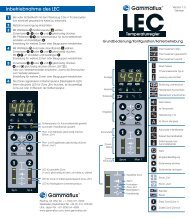
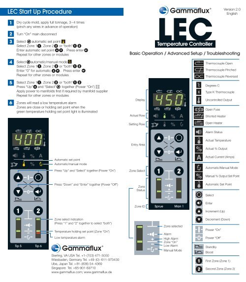
LEC Start Up Procedure<br />
1<br />
2<br />
3<br />
4<br />
5<br />
6<br />
Dry cycle mold, apply full tonnage, 3–4 times<br />
(pinch any wires in advance of operation)<br />
Turn “On” main disconnect<br />
Select automatic set point<br />
Select Zone 1 , Zone 2 or “both”<br />
Enter automatic set point . Press enter<br />
Repeat for other zones or modules<br />
Select automatic/manual mode<br />
Select Zone 1 , Zone 2 or “both”<br />
Enter “0” for automatic . . Press enter<br />
Repeat for other zones or modules<br />
Select Zone 1 , Zone 2 or “both”<br />
Press “Up” and “Select” together (Power “On”)<br />
Apply power to manifolds first if required by manifold supplier<br />
Repeat for other zones or modules<br />
Zones will read a low temperature alarm<br />
Zones are close or holding set point when the<br />
green temperature holding set point light is illuminated<br />
LEC<br />
Temperature Controller<br />
Version 2.0<br />
<strong>English</strong><br />
Basic Operation / Advanced Setup / Troubleshooting<br />
Display<br />
Actual Row<br />
C<br />
K<br />
Thermocouple Open<br />
Thermocouple Pinched<br />
Thermocouple Reversed<br />
Degrees C<br />
Type K Thermocouple<br />
Uncontrolled Output<br />
Open Fuse<br />
Shorted Heater<br />
Setting Row<br />
Open Heater<br />
Alarm Status<br />
Entry Area<br />
Actual Temperature<br />
Actual % Output<br />
Automatic set point<br />
Automatic/manual mode<br />
Press “Up” and “Select” together (Power “On”)<br />
Press “Down” and “Enter” together (Power “Off”)<br />
Zone Select<br />
Zone<br />
Status<br />
Actual Current (Amps)<br />
Automatic/Manual Mode<br />
Manual % Output Set Point<br />
Automatic Set Point<br />
Select<br />
Zone ID<br />
Sprue Man 1<br />
Enter<br />
Increment (Up)<br />
Tip 5 Tip 6<br />
Zone select indication<br />
(Press “1” and “2” together to select “both”)<br />
Temperature holding set point (Zone “On”)<br />
Low temperature alarm<br />
Sterling, VA USA Tel. +1-(703) 471-5050<br />
Wiesbaden, Germany Tel. +49-(0)-611-973430<br />
Ube, Japan Tel. +81-(836) 54-4369<br />
Singapore Tel. +65-901-83710<br />
www.gammaflux.com; www.gammaflux.de<br />
Zone selected<br />
Alarm<br />
High Alarm<br />
Zone “On”<br />
Low Alarm<br />
Manual Mode<br />
Decrement (Down)<br />
Power “On”<br />
Power “Off”<br />
Standby<br />
Boost<br />
First Zone (Zone 1)<br />
Second Zone (Zone 2)
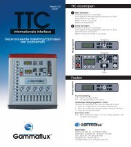
How to Enter a Set Point<br />
How to Select Automatic or Manual<br />
Enter Automatic Temperature Set Point<br />
1 Select zone(s) , or<br />
2 Select automatic set point<br />
3 Enter temperature set point<br />
4 Press enter to confirm<br />
1<br />
2<br />
3<br />
4<br />
Select zone(s) , or<br />
Select<br />
automatic/manual mode<br />
Enter “0” for automatic or closed loop control<br />
Enter “1” for manual or open loop control<br />
Press enter to confirm<br />
Automatic set point<br />
Press “Up” or “Down” to adjust temperature<br />
(Press “Up” and “Down” together to<br />
change individual digits – 100, 10 or 1)<br />
Select<br />
Enter<br />
Zone select indication<br />
(Press “1” and “2” together to select “both”)<br />
Automatic/Manual mode<br />
Select<br />
Enter<br />
Zone select<br />
Tip 1 Tip 2<br />
Tip 3 Tip 4<br />
Man 1<br />
Sprue<br />
Manual mode light<br />
(No light = automatic mode)<br />
How to Turn the Power “On” & “Off”<br />
Tip 1 Tip 2<br />
Turn zone(s) “On”<br />
1<br />
Select zone(s) , or<br />
2<br />
Press “Up” and “Select” together<br />
to turn power “On”<br />
Manual % output set point<br />
Select<br />
Zone(s) “On”<br />
Enter<br />
Zone(s) “Off”<br />
Zone select<br />
Press “1”, “2”, or “1 & 2” together<br />
to select “both”<br />
Enter Manual % Output Set Point<br />
1<br />
Select zone(s) , or<br />
Turn zone(s) “Off”<br />
2<br />
Select<br />
manual % output set point<br />
1<br />
Select zone(s) , or<br />
3<br />
4<br />
Enter manual % set point (0 – 99.9%)<br />
Press enter to confirm<br />
Tip 3 Tip 4<br />
Tip 1 Tip 2<br />
2<br />
Press “Down” and “Enter” together<br />
to turn power “Off”
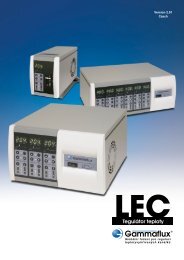
Standard Controller Enclosure Wiring<br />
13<br />
14<br />
15<br />
16<br />
17<br />
18<br />
19<br />
20<br />
21<br />
22<br />
23<br />
24<br />
6 & 12 Zone Enclosures HA4 Input/Output Connector<br />
1<br />
2<br />
3<br />
4<br />
5<br />
6<br />
7<br />
8<br />
9<br />
10<br />
11<br />
12<br />
Zone 1<br />
Zone 2<br />
Zone 3<br />
Zone 4<br />
Zone 5<br />
Zone 6<br />
Zone 7<br />
Zone 8<br />
Zone 9<br />
Zone 10<br />
Zone 11<br />
Zone 12<br />
1<br />
2<br />
3<br />
4<br />
5<br />
6<br />
7<br />
8<br />
9<br />
10<br />
11<br />
12<br />
(+) (-)<br />
13<br />
14<br />
15<br />
16<br />
17<br />
18<br />
19<br />
20<br />
21<br />
22<br />
23<br />
24<br />
Type J<br />
( - ) = Red<br />
( + ) = White<br />
Optional Network Module Wiring<br />
All Wiring Diagrams Represent Actual Connectors on Back Panels of LEC Controllers<br />
Standby input<br />
• 24 or 120 VAC/VDC input to activate<br />
• All zones go to standby mode<br />
• If standby set point is “1”, module will be inhibited<br />
• Configure in Advanced Setup<br />
• Male insert on enclosure<br />
Standby<br />
input<br />
2<br />
1<br />
G<br />
3<br />
4<br />
Alarm<br />
output<br />
Alarm output<br />
• 22 – 265 VAC/VDC must be supplied<br />
• Normally open contact<br />
• Contact is closed when any zone is in alarm for 16 seconds<br />
• Fused at 5 amps<br />
Power<br />
• Female insert on<br />
enclosure<br />
• Dual latch<br />
Thermocouple<br />
• Male insert on<br />
enclosure<br />
• Dual latch<br />
Remote Computer & Enclosure Link Connections<br />
9<br />
10<br />
11<br />
12<br />
13<br />
14<br />
15<br />
16<br />
(-) (+)<br />
1<br />
2<br />
3<br />
4<br />
5<br />
6<br />
7<br />
8<br />
2 Zone Enclosure<br />
Combination Power and Thermocouple<br />
• Female insert on enclosure<br />
• Dual latch<br />
Zone 1 Power<br />
Zone 2 Power<br />
Zone 1 Thermocouple<br />
Zone 2 Thermocouple<br />
Sterling, VA USA Tel. +1-(703) 471-5050<br />
Wiesbaden, Germany Tel. +49-(0)-611-973430<br />
Ube, Japan Tel. +81-(836) 54-4369<br />
Singapore Tel. +65-901-83710<br />
www.gammaflux.com; www.gammaflux.de<br />
• Female DB25 enclosure link<br />
connector on network<br />
module enclosure<br />
• Male DB25 enclosure link<br />
connector on stacked enclosure<br />
• Connect two enclosures to<br />
one network module<br />
• Share input, output and<br />
communications<br />
• Female DB9 remote computer<br />
connector on enclosure<br />
• Complimentary monitoring<br />
software including Gammavision,<br />
Mold Monitor, Mold Doctor and<br />
Field Calibrator
Advanced Setup<br />
The LEC controller is shipped to the<br />
customer so that no setup work is required<br />
for basic operation. Set points in automatic<br />
and manual may be entered and the zone<br />
will be controlled by turning “On” the power.<br />
Many customers require advanced features<br />
to satisfy their operation. This page will<br />
describe the basics of “Advanced Setup”.<br />
Please note that security level codes are not<br />
standard. To place security on the LEC<br />
controller you must activate security by<br />
selecting your own personalized security<br />
codes (network module required).<br />
Advanced<br />
setup<br />
number<br />
Press<br />
“Select”<br />
and “Enter”<br />
together<br />
Advanced Setup Guide - Level 2 Security to Change<br />
Advanced<br />
setup<br />
setting<br />
Press “Select”<br />
and “Enter”<br />
together<br />
again<br />
Toggle<br />
between<br />
number and<br />
setting<br />
Press<br />
“Select”<br />
to exit<br />
advanced<br />
setup<br />
# Limit (default) Explanation<br />
Set individually by zone<br />
(0) 0 - 4 (0) Power Priority. 0 = (off). 1 - 4 = increased smoothing of power output. A = Power Priority is active (setup number)<br />
(1) 0-999 (0) * Reset advanced setup to default values - enter 321; press enter to confirm<br />
(2) 0-100º F/55º C (20º F/11º C) Temperature deviation alarm set point (individual)<br />
Actual temperature activates individual zone alarm at this amount +/- set point<br />
(3) -31 to 27 (0) Control algorithm adjustment (individual). 0=auto selection. To view actual tuning value select code 4<br />
Manual Selections: 10 to 17 fast tuning with increasing lag. 20 to 27 slow tuning with increasing lag<br />
-17 to -10 fast manifold tuning with increasing lag. -27 to -20 very fast tuning with increasing lag<br />
-30 and -31 ultra fast low mass tuning. P = auto selection tune performed (setup number)<br />
(4) -31 to 27 (none) Algorithm set point (view only). View auto tuning selection or manual tuning value<br />
(5) 0-932º F/500º C (220º F/104º C) Standby set point (individual). When standby is activated, all automatic zones selected will control to this set point<br />
Entering “1” will inhibit the module (both zones), when activated the relays will open, turning “off” the module power<br />
(6) 0 to 54.0 minutes (5.0) T/C pinched detection time (individual)<br />
98+% output, 20º F/11º C in 5 minutes - default. Change alarm timer amount. 0 = disabled<br />
(7) 32-999º F/0-537º C (779º F/415º C) * Critical over temperature alarm. To clear the alarm, select alarm status and press enter<br />
If this temperature is exceeded for 8 seconds both zones turn “Off”. Max. 999º F (537º C) = disabled<br />
(8) 32-932º F/0-500º C (752º F/400º C) * Automatic set point limit. The maximum set point an operator can enter in automatic on both zones<br />
(9) 0-99.9% (99.9%) * Manual set point limit. The maximum set point an operator can enter in manual on both zones<br />
(10) 0-999º F/537º C (100º F/55º C) * Boost limit. The maximum amount of degrees an operator can raise or lower the zone(s) during a boost<br />
(11) +/-99º F/55º C (36º F/20º C) * Initial boost set point. Amount of degrees added to automatic set point, module adjustable within the boost limit<br />
(12) 0-999 seconds (120) * Boost time set point. The amount of time boost is active<br />
(13) 0 or 1 (0) * Degree F or C selection. 0=“degree F”; 1=“degree C”<br />
(14) 0 or 1 (0) * Type J or K thermocouple selection. 0=“type J”; 1=“type K”<br />
(15) 0 or 1 (0) * Zone power status on power up. 0 = all zones turned “Off”; 1= zones “On” when shut down last, stay “On”<br />
†<br />
(16) 0 or 1 (0) * Enable slaved power-up. 0=“Off”; 1=“On”. All zones heat within 20º F/11º C of one another until set point<br />
†<br />
(17) 0-999 (none) * Security code level 1. You must be in level 2 to change. Refresh procedure available, call <strong>Gammaflux</strong><br />
†<br />
(18) 0-999 (none) * Security code level 2. You must be in level 2 to change. Refresh procedure available, call <strong>Gammaflux</strong><br />
(19) - - - Output module controller software version/revision number (display only), select zone, version/revision displayed<br />
(20) - - - Temperature controller software version/revision number (display only), select zone, version/revision displayed<br />
(21) 0 (0) LED test. To activate enter 0. Turns “On” all LED’s for troubleshooting<br />
†<br />
(22) 000-999 (level 2) Security level indicated. 0=lockout; 1=operator; 2=supervisior. 0 - enter, drops one level<br />
Elevate one security level at a time with your customized code<br />
†<br />
Network module required * Network module distribution or value applies to both zones on the module
Why Standby? How to Activate<br />
Alternate Standby Inputs<br />
Some processors like to maintain a<br />
lower set point on command for all zones<br />
while they are working on something.<br />
Select zone(s) to put into standby , or<br />
Press “down” and “select” together<br />
The selected zone(s) will go to the<br />
standby temperature<br />
Hotter zones will cool to the standby temperature<br />
Colder zones will heat to the standby temperature<br />
Automatic zones = 220º F/104º C (default)<br />
Manual zones = half of the manual set point<br />
The outer decimal points will flash during standby<br />
To cancel standby,<br />
press “down” and “select” together<br />
Standby switch on enclosure<br />
(if available) all zones go to standby mode<br />
Standby<br />
input<br />
2<br />
1<br />
G<br />
3<br />
4<br />
Tip 1 Tip 2<br />
The original standby source must be cancelled<br />
to clear standby. Please reference alternate<br />
standby inputs, shown to the right<br />
• 24 or 120 VAC/VDC input to activate<br />
• All zones go to standby mode<br />
(network module required)<br />
• Standby button from<br />
external software<br />
• Selected zone(s) go to standby<br />
mode (network module required)<br />
Why Boost? How to Boost<br />
How to View All Zones Quickly<br />
Boost temporarily raises a zone(s) temperature<br />
(typically tips) to clear a cold slug on start up.<br />
Select zone(s) to boost , or<br />
Press “up” and “enter” together<br />
Enter boost amount . Press enter<br />
Zone(s) will boost 36ºF/20ºC (default)<br />
for 120 seconds (default)<br />
The 7 segment display will flash during boost<br />
Alarm<br />
status<br />
Select<br />
Zone<br />
select<br />
1 Tip 1 - in alarm, select zone<br />
Select alarm status<br />
Thermocouple open<br />
2 Tip 2 - normal operation<br />
Zone is on, in automatic<br />
and at or near set point<br />
3 Tip 3 - in manual,<br />
Thermocouple may be open<br />
Module applying a constant<br />
% output to the heater<br />
4 Tip 4 - in automatic,<br />
High temperature alarm<br />
(+20º F/11º C default)<br />
5 Man 1 - normal operation<br />
6 Sprue - low alarm<br />
To cancel boost,<br />
press “up” and “enter” together<br />
Tip 1 Tip 2 Tip 1 Tip 2 Tip 3 Tip 4 Man 1 Sprue
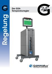
Basic Troubleshooting<br />
Thermocouple pinched - The T/C is pinched or<br />
the controller thinks it is pinched. (Default: 98+<br />
% output, must see +20º F/11º C in 5 minutes).<br />
True pinch - the T/C is sensing the temperature<br />
further away from the heat source than intended.<br />
Without alarm, temperature reads low, controller<br />
applies power, runaway heat. False T/C pinch -<br />
heater is too small to heat the zone or the T/C<br />
is located too far away. Replace heater, move T/C<br />
or adjust alarm. Selectable detection times in<br />
advanced setup<br />
Thermocouple (T/C) open - the T/C connection is<br />
broken, follow general troubleshooting<br />
Open heater - The heater connection is broken,<br />
follow general troubleshooting<br />
Shorted heater - The heater is shorted or exceeds<br />
the maximum rating of the module, follow general<br />
troubleshooting<br />
Open fuse - fuse on module bad. Turn “Off” main<br />
disconnect. Remove top cover, locate module,<br />
check all fuses (4 per module, 2 per zone)<br />
Thermocouple reversed - The T/C connection is<br />
wired + to - at some point. Visually inspect each<br />
connection, for type J (US standard) red wire<br />
should connect to red wires, not red to white<br />
Critical over temperature - The temperature of a<br />
zone exceeded the alarm limit. (Default: 779ºF/<br />
415º C). Both zones on the module shut “off”<br />
automatically. To clear the alarm, select alarm<br />
status and press enter. Noted by vertical<br />
indicator segment<br />
Uncontrolled output - The module has an<br />
unregulated output. Both zones on the module<br />
shut “off” automatically. To clear the alarm, select<br />
alarm status and press enter. Noted by vertical<br />
and horizontal indicator segment (shown)<br />
Over-Voltage - The module line voltage<br />
exceeded 280 VAC for 1 minute<br />
(informational only)<br />
General Troubleshooting – Turn “Off” Main Disconnect<br />
1<br />
Check resistance from pin to pin, at the mold. T/C should read 3-50 ohms at room<br />
temperature. Heater should read greater than 16 ohms. If there is no continuity<br />
(open line) = broken connection, open heater or open T/C.<br />
1<br />
2<br />
2<br />
Check resistance from pin to ground, at the mold. Heaters only - no continuity<br />
(open line) = good. Some resistance is bad, heater shorted.<br />
13<br />
3<br />
4<br />
Reattach the cable to the mold, detach the cable from the controller. Check<br />
resistance from pin to pin on the cable. T/C should read 3-50 ohms at room<br />
temperature. Heater should read greater than 16 ohms. If there is no continuity<br />
(open line) = broken connection, open heater or open T/C. The connection is<br />
broken in the cable set or the connectors/pins are not making contact.<br />
Reattach the cable to the mold, detach the cable from the controller. Check<br />
resistance from pin to ground on the cable. Heaters only - no continuity<br />
(open line) = good. Some resistance is bad, heater shorted. The wires are either<br />
shorted in the cable set or the connectors are shorted to ground.<br />
12<br />
14<br />
5<br />
3<br />
10<br />
8<br />
9<br />
7<br />
6<br />
5<br />
6<br />
At this point if everything is fine, the problem is in the controller. (1) turn “Off”<br />
main disconnect, (2) locate problem module, (3) check fuses on module,<br />
(4) swap bad module into a known good location, (5) turn “On” main disconnect,<br />
(6) test the zone. If the problem follows the module = bad module. If the alarm<br />
stays with the original zone, the problem is between the module and the<br />
connectors on the rear of the enclosure.<br />
If the problem is not explained, or you need spare parts please contact:<br />
<strong>Gammaflux</strong> USA +1-(703) 471-5050<br />
info@gammaflux.com; www.gammaflux.com<br />
<strong>Gammaflux</strong> Europe +49-(0)-611-973430<br />
info@gammaflux.de; www.gammaflux.de<br />
<strong>Gammaflux</strong> Asia-Pacific<br />
Japan Tel. +81-(836) 54-4369<br />
Singapore Tel. +65-901-83710<br />
gammafluxjpn@gammaflux.com<br />
1<br />
2<br />
3<br />
4<br />
5<br />
6<br />
11<br />
Output module<br />
Module thermocouple/<br />
communications cable<br />
Module power input/<br />
output connector<br />
(base of module)<br />
Input power cable<br />
Main disconnect (circuit breaker)<br />
Thermocouple input connector<br />
7<br />
8<br />
9<br />
10<br />
11<br />
12<br />
13<br />
14<br />
4<br />
Power output connector<br />
Auxiliary input/output connector<br />
Enclosure link connector<br />
Communications port<br />
Ground stud<br />
Fan<br />
System wide standby switch<br />
(on front)<br />
Capacitors