Flow Technology High Shock Turbine Flowmeters - HS Series
Flow Technology High Shock Turbine Flowmeters - HS Series
Flow Technology High Shock Turbine Flowmeters - HS Series

You also want an ePaper? Increase the reach of your titles
YUMPU automatically turns print PDFs into web optimized ePapers that Google loves.
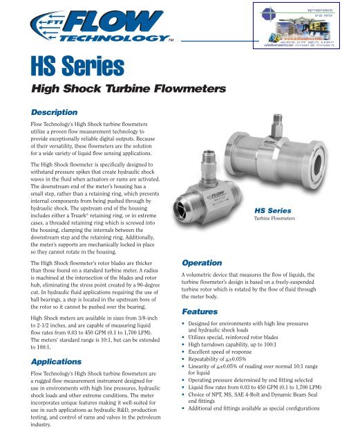
<strong>HS</strong> <strong>Series</strong><br />
<strong>High</strong> <strong>Shock</strong> <strong>Turbine</strong> <strong>Flow</strong>meters<br />
Description<br />
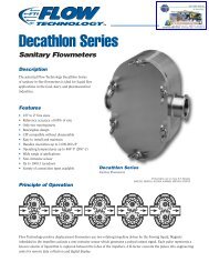
<strong>Flow</strong> <strong>Technology</strong>’s <strong>High</strong> <strong>Shock</strong> turbine flowmeters<br />
utilize a proven flow measurement technology to<br />
provide exceptionally reliable digital outputs. Because<br />
of their versatility, these flowmeters are the solution<br />
for a wide variety of liquid flow sensing applications.<br />
The <strong>High</strong> <strong>Shock</strong> flowmeter is specifically designed to<br />
withstand pressure spikes that create hydraulic shock<br />
waves in the fluid when actuators or rams are activated.<br />
The downstream end of the meter’s housing has a<br />
small step, rather than a retaining ring, which prevents<br />
internal components from being pushed through by<br />
hydraulic shock. The upstream end of the housing<br />
includes either a Truark ® retaining ring, or in extreme<br />
cases, a threaded retaining ring which is screwed into<br />
the housing, clamping the internals between the<br />
downstream step and the retaining ring. Additionally,<br />
the meter’s supports are mechanically locked in place<br />
so they cannot rotate in the housing.<br />
The <strong>High</strong> <strong>Shock</strong> flowmeter’s rotor blades are thicker<br />
than those found on a standard turbine meter. A radius<br />
is machined at the intersection of the blades and rotor<br />
hub, eliminating the stress point created by a 90-degree<br />
cut. In hydraulic fluid applications requiring the use of<br />
ball bearings, a step is located in the upstream bore of<br />
the rotor so it cannot be pushed over the bearing.<br />
<strong>High</strong> <strong>Shock</strong> meters are available in sizes from 3/8-inch<br />
to 2-1/2 inches, and are capable of measuring liquid<br />
flow rates from 0.03 to 450 GPM (0.1 to 1,700 LPM).<br />
The meters’ standard range is 10:1, but can be extended<br />
to 100:1.<br />
Applications<br />
<strong>Flow</strong> <strong>Technology</strong>’s <strong>High</strong> <strong>Shock</strong> turbine flowmeters are<br />
a rugged flow measurement instrument designed for<br />
use in environments with high line pressures, hydraulic<br />
shock loads and other extreme conditions. The meter<br />
incorporates unique features making it well-suited for<br />
use in such applications as hydraulic R&D, production<br />
testing, and control of rams and valves in the petroleum<br />
industry.<br />
Operation<br />
A volumetric device that measures the flow of liquids, the<br />
turbine flowmeter’s design is based on a freely-suspended<br />
turbine rotor which is rotated by the flow of fluid through<br />
the meter body.<br />
Features<br />
<strong>HS</strong> <strong>Series</strong><br />
<strong>Turbine</strong> <strong>Flow</strong>meters<br />
• Designed for environments with high line pressures<br />
and hydraulic shock loads<br />
• Utilizes special, reinforced rotor blades<br />
• <strong>High</strong> turndown capability, up to 100:1<br />
• Excellent speed of response<br />
• Repeatability of
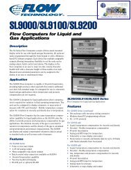
Model Numbering System<br />
<strong>HS</strong> Sizing<br />
5-Digit AE, NE DB End Meter Normal <strong>Flow</strong> Extended Range Based on<br />
<strong>Series</strong> & 62 End Fitting ID Range 10:1 Normal Range<br />
& Size Fitting SAE AS<br />
Nominal 85720/01<br />
Ball Bearings Journal Bearings NOMINAL<br />
K-FACTOR<br />
APPROX.<br />
GPM LPM RF MIN MAG MIN RF MIN MAG MIN ALL MAX<br />
in. mm MIN MAX MIN MAX GPM LPM GPM LPM GPM LPM GPM LPM GPM LPM P/G P/L Hz<br />
<strong>HS</strong> 4-6 3/8 -06 .30 7.6 .25 2.5 .95 9.5 .03 .11 .10 .38 .10 .38 .12 .45 3 11 48000 12680 2000<br />
<strong>HS</strong> 4-8 1/2 -07 .30 7.6 .25 2.5 .95 9.5 .03 .11 .10 .38 .10 .38 .12 .45 3 11 48000 12680 2000<br />
<strong>HS</strong> 6-8 1/2 -07 .37 9.4 .50 5.0 1.9 19 .05 .19 .12 .45 .15 .57 .20 .76 5 19 25000 6600 2100<br />
<strong>HS</strong> 8-8 1/2 -08 .40 10 .75 7.5 2.8 28 .08 .30 .16 .60 .20 .76 .25 .95 8 30 16000 4200 2000<br />
<strong>HS</strong>-08 1/2 -09 .44 11 1.00 10.0 3.8 38 .10 .38 .20 .76 .25 .95 .30 1.1 10 38 12000 3170 2000<br />
<strong>HS</strong>-10 *5/8, 3/4 -10 .50 13 1.25 12.5 4.7 47 .15 .57 .30 1.1 .30 1.1 .40 1.5 15 56 9600 2540 2000<br />
<strong>HS</strong>-12 3/4 -12 .56 14 2 20 7.6 76 .25 .95 .50 1.9 .50 1.9 .50 1.9 25 94 6000 1580 2000<br />
<strong>HS</strong>-16 1 -16 .86 22 5 50 19 190 0.6 2.3 1.0 3.8 1.0 3.8 1.0 3.8 60 227 2400 635 2000<br />
<strong>HS</strong>-20 1-1/4 -20 1.00 25 9 90 34 340 1.0 3.8 1.5 5.7 1.0 3.8 1.5 5.7 100 378 1300 345 1950<br />
<strong>HS</strong>-24 1-1/2 N/A 1.32 34 15 150 57 570 1.6 6.0 2.5 9.5 1.6 6.0 2.5 9.5 160 605 600 160 1500<br />
<strong>HS</strong>-32 2 N/A 1.75 44 22 225 85 850 2.5 9.5 3.5 13 2.5 9.5 3.5 13 250 946 350 92 1300<br />
<strong>HS</strong>-40 2-1/2 N/A 2.22 56 40 400 151 1510 4.5 17 5.0 19 4.5 17 5.0 19 450 1700 180 48 1200<br />
Abbreviations for Units of Measure:<br />
GPM = Gallons per Minute<br />
LPM = Liters per Minute<br />
P/G = Pulses per Gallon<br />
P/L = Pulses per Liter<br />
End Fittings<br />
AE = AN (or MS) external straight threads, 37° flare<br />
NE = NPT external threads<br />
DB = Dynamic Beam Seal, per SAE AS 85720/01<br />
Note: “DB” fitting available up to size <strong>HS</strong>-20<br />
Black = English (US) Units<br />
Blue = Metric (SI) Units<br />
English units in GPM<br />
Metric units in LPM<br />
62 = SAE Code 62, 4-bolt split flange<br />
Note: “62” fitting available for <strong>HS</strong> 4-8 – <strong>HS</strong>-32<br />
* <strong>HS</strong>-10 “AE” fitting is 5/8". NE and 62 fittings are 3/4"<br />
Calibration<br />
CODE DESCRIPTION<br />
Note: W=Water, S=Solvent, B=Oil Blend<br />
Viscosity must be provided with oil blend calibrations “B”<br />
NW 10-point, normal 10:1 range, in water<br />
NS 10-point, normal 10:1 range, in solvent<br />
NB 10-point, normal 10:1 range, in oil blend<br />
XW 10-point, extended range, in water<br />
XS 10-point, extended range, in solvent<br />
XB 10-point, extended range, in oil blend<br />
TW 20-point, normal 10:1 range, in water<br />
TS 20-point, normal 10:1 range, in solvent<br />
TB 20-point, normal 10:1 range, in oil blend<br />
YW 20-point, extended range, in water<br />
YS 20-point, extended range, in solvent<br />
YB 20-point, extended range, in oil blend<br />
U2 Universal Viscosity Curve, 2 Viscosities<br />
(specify minimum viscosity & maximum<br />
viscosity). 10 points each viscosity<br />
U3 Universal Viscosity Curve, 3 Viscosities<br />
(specify minimum viscosity & maximum<br />
viscosity). 10 points each viscosity<br />
AN (MS)<br />
NPT<br />
SAE<br />
Code 62<br />
Dynamic<br />
Beam Seal<br />
H<br />
S<br />
<strong>Series</strong> & Size<br />
End Fittings<br />
Calibration
Special<br />
If the full normal 10:1 flow range or the full extended flow<br />
range is required and the units of measure are GPM, insert a<br />
dash “–” in this location for standard range and units.<br />
If a flow range other than the normal 10:1 or extended flow<br />
range, or if units of measure other than GPM are required,<br />
insert an “S” in this position. When an “S” is used in this<br />
position, the minimum and maximum flow range, as well<br />
as the units of measure, must be spelled out.<br />
Liquid<br />
Materials of Construction<br />
MATERIAL<br />
CODE HOUSING ROTOR<br />
E 316 SST 430F SST<br />
Bearings<br />
Bearing selection will affect flow range.<br />
Refer to sizing specification table for<br />
correct flow ranges.<br />
A — Ball Bearings (440 C)<br />
D — Carbide Journal (Carbide Shaft<br />
& Sleeve) — liquid only<br />
Pickoffs<br />
The following is a listing of some of the pickoffs that<br />
are available from <strong>Flow</strong> <strong>Technology</strong>.<br />
–1 = Modulated Carrier, MS connector<br />
–2 = Magnetic, MS connector<br />
–3 = Magnetic, flying leads/threaded connection<br />
–5 = Modulated Carrier, flying leads/threaded<br />
connection<br />
–6 = Magnetic, MS connector, 750° F/400° C max.<br />
–7 = Magnetic, flying leads/threaded connection<br />
750° F/400° C max.<br />
–L = Modulated Carrier, MS connector, 750° F/<br />
400° C max.<br />
–M = Modulated Carrier, flying leads/threaded<br />
connection 750° F/400° C max.<br />
T1 = Modulated Carrier w/RTD, MS connector<br />
T2 = Magnetic w/RTD, MS connector<br />
T3 = Magnetic w/RTD, flying leads/threaded<br />
connection<br />
T5 = Modulated Carrier w/RTD, flying leads/<br />
threaded connection<br />
–X = Modulated Carrier, I.S. approved, MS connector<br />
XX = Modulated Carrier, I.S. approved, flying<br />
leads/threaded body<br />
–U = Magnetic, I.S. approved, MS connector<br />
TT = Magnetic, I.S. approved, flying leads/<br />
threaded body<br />
Notes:<br />
1. Maximum temperature rating of pickoffs are<br />
350° F (177° C) unless otherwise noted.<br />
2. See Amplifier Link literature for amplified<br />
pickoff codes.<br />
Please note:<br />
<strong>High</strong>lighted areas indicate standard base<br />
price configuration.<br />
Optional<br />
Designators<br />
L<br />
– = Standard<br />
S = Special/Range or Units<br />
Material Bearing Pickoff<br />
Optional Designators<br />
(Consult Factory)
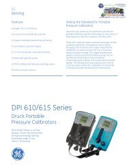
Dimensions<br />
AE, NE or DB Fittings<br />
<strong>Series</strong> A B<br />
in. mm in. mm<br />
<strong>HS</strong>4-6 2.45 62 1.00 25<br />
<strong>HS</strong>-8 2.45 62 1.00 25<br />
<strong>HS</strong>-10 2.72 69 1.38 35<br />
<strong>HS</strong>-12 3.25 83 1.38 35<br />
<strong>HS</strong>-16 3.56 90 1.63 41<br />
<strong>HS</strong>-20 4.06 103 1.88 48<br />
<strong>HS</strong>-24 4.59 117 2.25 57<br />
<strong>HS</strong>-32 6.06 154 2.75 70<br />
<strong>HS</strong>-40 8.90 226 3.50 89<br />
PICKOFF<br />
B<br />
FLATS<br />
Drawing to the right<br />
shows a Code 62<br />
end connection.<br />
Pickoff is a 2-pin<br />
MS connector.<br />
A<br />
END-TO-END<br />
øB<br />
2.0" MAX<br />
50.8mm<br />
Code 62 Fittings<br />
<strong>Series</strong> A B<br />
in. mm in. mm<br />
<strong>HS</strong>-8 4.64 118 1.25 32<br />
<strong>HS</strong>-10 5.13 130 1.63 41<br />
<strong>HS</strong>-12 5.13 130 1.63 41<br />
<strong>HS</strong>-16 5.63 143 1.88 48<br />
<strong>HS</strong>-20 5.63 143 2.13 54<br />
<strong>HS</strong>-24 6.63 168 2.50 64<br />
<strong>HS</strong>-32 7.63 194 3.13 80<br />
Drawing to the left shows MS<br />
end connections. Pickoff is a<br />
2-pin MS connector.<br />
A<br />
END-TO-END<br />
2.0" MAX<br />
50.8mm<br />
Specifications<br />
Materials of Construction<br />
Standard<br />
Operating Temperature<br />
Range<br />
Bearing Type<br />
316 SST Housing<br />
430F SST Rotor<br />
440 C Ball Bearings<br />
Stainless steel all other wetted parts<br />
Defined by pickoff and bearing selection<br />
Temperature Limits:<br />
440 C stainless steel<br />
ball bearings -450° F to +300° F (-270° C to +150° C)<br />
Note: Not recommended for water service.<br />
Tungsten carbide<br />
journal bearings -100° F to +1,200° F (-75° C to +650° C)<br />
Pickoff Type<br />
Temperature Limits:<br />
Magnetic -430° F to +350° F (-260° C to +177° C)<br />
Output:<br />
10 mV min.<br />
<strong>High</strong> Temp. Magnetic -430° F to +750° F (-260° C to +400° C)<br />
Output:<br />
10 mV min.<br />
Modulated Carrier (RF) -300° F to +350° F (-185° C to +177° C)<br />
<strong>High</strong> Temp. (RF) Up to 750° F (400° C)<br />
Pickoff Electronic Connections<br />
MS Connector<br />
2-pin, standard pickoff: 15-89515-101<br />
3-pin, amplified pickoff: 15-89515-102<br />
4-pin, pickoff with RTD: 15-93825-01<br />
Threaded Connection<br />
with Leads<br />
Junction Box with Terminal: 73-31836-105<br />
Operating Pressure Range<br />
Filtration Recommendations<br />
Ball Bearings<br />
Journal Bearings<br />
Defined by end connection<br />
10 micron to 100 micron (with<br />
less filtration for large sizes)<br />
100 micron<br />
Performance Specifications<br />
Performance specifications are based on a viscosity of 1.2 centistokes<br />
using ball bearings.<br />
Calibration Accuracy<br />
Repeatability<br />
Linearity<br />
Pressure Drop<br />
Dynamic Response<br />