Passivated Emitter Rear Locally Diffused Solar Cells
Passivated Emitter Rear Locally Diffused Solar Cells
Passivated Emitter Rear Locally Diffused Solar Cells

You also want an ePaper? Increase the reach of your titles
YUMPU automatically turns print PDFs into web optimized ePapers that Google loves.
<strong>Passivated</strong> <strong>Emitter</strong> <strong>Rear</strong> <strong>Locally</strong> <strong>Diffused</strong> <strong>Solar</strong> <strong>Cells</strong><br />
<strong>Passivated</strong> <strong>Emitter</strong> <strong>Rear</strong> <strong>Locally</strong> <strong>Diffused</strong><br />
<strong>Solar</strong> <strong>Cells</strong><br />
李 玉 飞<br />
ABSTRACT High efficiency passivated emitter, rear locally-diffused (PERL) solar cells and Silicon solar cells with<br />
passivated emitter and rear contacts (PERC) are both developed by ARC (Australian Research Council) Photovoltaics<br />
Centre of Excellence, University of New South Wales. The former technology has a significant enhancement in the<br />
energy conversion effi ciency of mono-crystalline silicon solar cells up to 25% under the standard global solar spectrum<br />
which is the world record in photovoltaic area. (Used to be 24.7%, however there is a 0.3% improvement due to the new<br />
standard calculation of Air Mass 1.5) Under monochromatic light which wavelength is 1.04 , energy conversion effi ciency<br />
is 46.3% [1] . The passivated emitter cell series (PESC, PERC and PERL), which are invented or incorporated by UNSW,<br />
have made a key contribution to increase the energy conversion effi ciency in photovoltaic area.<br />
1 PERL Cell Structures used in<br />
this Research<br />
The PERL solar cell got a conversion efficiency of 23.1%<br />
in 1990 [2, 3] . And it had been redesigned in 1993, the<br />
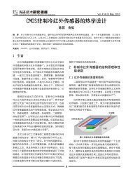
structure of cell shown in Fig. 1. [4]<br />
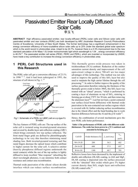
Fig.1. Schematic of a PERL (or LBSF) cell on a p-type Fz<br />
Si wafer.<br />
The key features of PERL cells are: The top surface of the<br />
solar cell is textured using inverted-pyramid structures<br />
and covered by double-layer anti-reflection coating (ARC)<br />
which brings extremely low top surface reflection. The<br />
front metal finger grids are defined by photolithography<br />
technology to be very thin therefore minimising metal<br />
shading loss. Both inverted-pyramid texturing and fine<br />
metal fingers decrease the optical losses which contribute<br />
to higher current for the solar cell. A selective emitter<br />
(heavily phosphorus diffused regions underneath the<br />
metal contacts) whilst the rest of the top surface is lightly<br />
diffused to keep excellent “blue response” (absorbing the<br />
short-wavelength photons), it can minimise both contact<br />
resistance and contact area recombination.<br />
Thermal oxide passivation of the silicon/ silicon dioxide<br />
interface which can reduce surface recombination.<br />
41<br />
This thermally grown oxide process was taken in<br />
trichloroethane (TCA) ambient. Reduction of the emitter<br />
saturation current density and improvement of the cell<br />
open-circuit voltage to above 700-mV are two major<br />
advantages of this technology. This method was not only<br />
used to improve the quality of this SiO 2 layer but also<br />
used to maintain the high carrier lifetime through the cell<br />
processing [5] . In order to further improve the quality of the<br />
surface passivation therefore reducing the thickness of the<br />
thermally grown oxide to below 300Å, this SiO 2 layer was<br />
treated with an “alneal” process, “which is performed by<br />
coating a layer of aluminum on top of SiO 2 , sintering in<br />
forming gas at about 370℃ for 30 min, and then removing<br />
the aluminum layer [6] ”. Last but not least, a point contacted<br />
rear surface (local boron diffusions) with thermal oxide<br />
passivation in the non-contacted rear surface regions which<br />
is covered with Al, further reducing surface recombination<br />
due to the Alneal effect and the band bending due to work<br />
function differences between the Al and the p-Si wafer [7] .<br />
Hence, the combination of several mechanisms gave the<br />
new PERL cells better performance.<br />
Table 1:The performance of PERL cells with different oxide<br />
thicknesses. The oxide has been grown in a TCA ambient and<br />
annealed in forming gas. [1]<br />
Cell ID Oxide thickness (Å) J sc (mA/cm 2 )<br />
V oc<br />
(mV)<br />
W4-19-2E 200 36.5 682<br />
Z4-16-2E 600 37.5 697<br />
W4-6-1H 1100 40.7 703<br />
Reflective losses have been decreased by the implement of<br />
double anti-reflection (DLAR) coating, (a ZnS and MgF 2<br />
DLAR coating is deposited onto the surface processed<br />
with the “alnealed” thin oxide) which gave 3% higher<br />
current density than SiO 2 single layer anti-reflection<br />
(SLAR) coated cells. [1]
Vol. 5 No.8/ Aug. 2011<br />
Table 2:The measured effective minority carrier lifetimes<br />
at different processing stages for an 1.5 cm FZ wafer with<br />
1100 Å TCA grown oxide. “Alneal” and forming gas alneal<br />
significantly improved the carrier lifetimes. [1]<br />
Processing stage<br />
After TCA oxidation<br />
Tau<br />
14 s<br />
Table 4:<br />
Cell Technology Diagram of <strong>Rear</strong> Surface Design Voc (mV) Reference<br />
PERC<br />
(0.2 .cm, 696 (Blakers et al. 1989)<br />
p-type, FZ)<br />
After sinter in forming gas<br />
Cell ID<br />
After “alneal”<br />
Substrate<br />
Resistivity<br />
( cm)<br />
V oc<br />
(mV)<br />
Jsc<br />
(mA/cm 2 )<br />
40 s<br />
400 s<br />
Table 3: The performance of 4 cm 2 PERL FZ cells tested at<br />
Sandia National Laboratories under the standard global<br />
AM1.5 spectrum (100mW/cm 2 ) at 25℃. [5]<br />
FF<br />
(%)<br />
Effic.<br />
(%)<br />
Wh20-2b 1.0 706 42.2 82.8 24.7<br />
PERC cell structures and key feature:<br />
The passivated emitter and rear cell (PERC) structure<br />
was developed by Blakers et al. (UNSW) in 1988 and it<br />
has only a slightly lower efficiency potential than a more<br />
complex structure with rear local diffusions (PERL) [7] .<br />
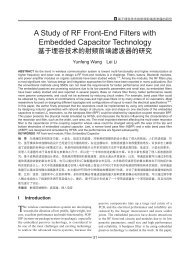
Fig 2. The PERC cell structure. The surface texturing is not<br />
shown. [8]<br />
It has a lightly phosphorous doped emitter with heavier<br />
diffusions under the front contacts (selective emitter),<br />
a silicon/silicon dioxide interface passivation and antireflection<br />
coating, and inverted pyramids on the top<br />
surface. <strong>Rear</strong> contact is connected with the substrate by<br />
contact holes through the rear oxide covering about 1% of<br />
the rear surface, without the use of boron diffusion (p ++ )<br />
by comparing with PERL solar cell model. The design is<br />
simpler than the PERL structure, avoids boron diffusion<br />
which keeps recombination at the rear contacts low.<br />
Owing to minimise contact recombination, the area of the<br />
holes is larger than the cell thickness. “The substrate of<br />
the record efficiency cell was moderately doped (0.2–0.5<br />
cm) in order to reduce series resistance due to the widely<br />
spaced contacts and to allow low resistance contact to be<br />
made with aluminum to the substrate [7] .”<br />
42<br />
PERL<br />
(2 .cm, 696 (Wang et al. 1990)<br />
p-type, FZ)<br />
=============================================================<br />
Various low-area localised rear contacting schemes used<br />
in the fabrication of high efficiency Si solar cell (the front<br />
surfaces are omitted from the diagrams) [9] .<br />
In the PERC structure, the rear comprised of SiO 2 -<br />
passivated p-type surface with<br />
photolithographically defined localised metal directly<br />
contacting the substrate. From passivation point of view,<br />
the PERL cell was almost the same with the PERC<br />
passivation except for the reduction of dark saturation<br />
current owing to the metal contact regions where PERL<br />
were passivated with heavy boron diffusion, which built<br />
high-low junction for it [9] . The passivated emitter and<br />
rear contacts solar cell (PERC) structure produced record<br />
efficiency silicon cells 1980s.<br />
2 Conclusion<br />
PERL and PERC solar cell both are first generation<br />
silicon solar cell (using silicon as substrate), which<br />
have dominated photovoltaic industry for decades.<br />
Some industrial technologies are based those laboratory<br />
techniques, such as Pluto technology of Suntech Power,<br />
the world's largest photovoltaic (PV) module manufacturer.<br />
They announced that their Pluto technology which is based<br />
on the PERL technology produce PV cells with conversion<br />
efficiencies of approximately 19% on mono-crystalline PV<br />
cells and 17% on multi-crystalline PV cells. It means that<br />
this technology is used in large scale production now.<br />
References<br />
[1] J. Zhao, A. Wang, Stuart Wenham, Martin Green, “24% Efficient<br />
PERL silicon solar cell: recent improvements in high efficiency<br />
silicon cell research”, <strong>Solar</strong> Energy Material and <strong>Solar</strong> <strong>Cells</strong>,<br />
1996.<br />
[2] A. Wang, J. Zhao and M.A. Green, Appl. Phys. Lett.57 (1990)<br />
602.<br />
[3] M.A. Green and K. Emery, Progr. Photovoltaics. 2 (1994) 27.<br />
[4] Martin A. Green, “Silicon <strong>Solar</strong> <strong>Cells</strong>: Advanced Principles<br />
& Practice”, Centre for Photovoltaic Devices and Systems,<br />
University of New South Wales, Sydney, 1995<br />
[5] J. Zhao, A. Wang, M.A. Green, “High-efficiency PERL and<br />
PERT silicon solar cells on FZ and MCZ substrates”, <strong>Solar</strong><br />
Energy Material and <strong>Solar</strong> <strong>Cells</strong>, 2001.<br />
[6] P. Balk, in: The Si-SiO2 System, Elsevier, Amsterdam, 1988, p.
<strong>Passivated</strong> <strong>Emitter</strong> <strong>Rear</strong> <strong>Locally</strong> <strong>Diffused</strong> <strong>Solar</strong> <strong>Cells</strong><br />
234.<br />
[7] A.W. Blakers, A. Wang, A.M. Milne, J. Zhao, M.A. Green, Appl.<br />
Phys. Lett. 55 (13) (1989) 1363.<br />
[8] K.R. Catchpole, A.W. Blakers, “Modelling the PERC structure<br />
for industrial quality silicon”, <strong>Solar</strong> Energy Material and <strong>Solar</strong><br />
<strong>Cells</strong>, 2002.<br />
[9] Utama R. Y. Ph.D Thesis, “Inkjet Printing for Commercial High-<br />
Efficiency Silicon <strong>Solar</strong> <strong>Cells</strong>”, University of New South Wales,<br />
2009.<br />
<br />
研 究 助 理 ,2010 年 毕 业 于 澳 大 利 亚 新 南 威 尔<br />
士 大 学 光 伏 与 太 阳 能 专 业 , 获 得 硕 士 学 位 。<br />
主 要 研 究 单 晶 硅 , 多 晶 硅 第 一 代 太 阳 能 电 池<br />
制 造 及 封 装 工 艺 , 设 计 光 伏 并 网 发 电 和 独 立<br />
光 伏 发 电 系 统 , 并 积 累 丰 富 经 验 , 对 第 二 代<br />
电 池 中 的 多 晶 硅 沉 淀 在 玻 璃 上 的 PECVD 工<br />
艺 有 清 晰 认 识 和 理 解 , 了 解 第 三 代 电 池 中 利<br />
用 量 子 点 阵 控 制 hot carrier 和 制 造 tandem<br />
cell 提 高 电 池 效 率 的 概 念 和 工 艺 过 程 。 参 与<br />
“540KwP Grid connected PV system<br />
in Mae Hong Son Thailand” 项 目 ,<br />
“Stand-alone PV system in Australia”<br />
项 目 。<br />
43