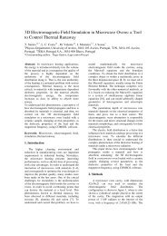
Recent Advances in Fresnel Zone Plate Antenna Technology
Recent Advances in Fresnel Zone Plate Antenna Technology
Recent Advances in Fresnel Zone Plate Antenna Technology

Create successful ePaper yourself
Turn your PDF publications into a flip-book with our unique Google optimized e-Paper software.
<strong>Recent</strong> <strong>Advances</strong> <strong>in</strong> <strong>Fresnel</strong> <strong>Zone</strong> <strong>Plate</strong> <strong>Antenna</strong> <strong>Technology</strong><br />
S. M. StoutGrandy #1 , A. Petosa #2 , I.V. M<strong>in</strong><strong>in</strong> #3 , O.V. M<strong>in</strong><strong>in</strong> #3 , J.S. Wight #1<br />
#1<br />
Department of Electronics, Carleton University<br />
1125 Colonel By Drive, Ottawa, Ontario, K1S 5B6, Canada<br />
sstout@doe.carleton.ca, jsw@doe.carleton.ca<br />
*2<br />
Advanced <strong>Antenna</strong> <strong>Technology</strong> Group, Communications Research Centre Canada<br />
3701 Carl<strong>in</strong>g Ave., Ottawa, K2H 8S2, Canada<br />
aldo.petosa@crc.ca<br />
#3<br />
Department of Information Protection, Novosibirsk State Technical University (NSTU)<br />
20 Karl Marx Prospect, Novosibirsk, 630092, Russia<br />
igor.m<strong>in</strong><strong>in</strong>@ngs.ru, prof.m<strong>in</strong><strong>in</strong>@gmail.com<br />
Abstract: This paper outl<strong>in</strong>es some of the recent advances <strong>in</strong> <strong>Fresnel</strong> zone plate antenna<br />
technology. Sidelobe reduction and control over sidelobe location are two developments which<br />
are useful for <strong>in</strong>terference reduction. Another development is the focus<strong>in</strong>g resolution of <strong>Fresnel</strong><br />
zone plate antennas for subwavelength focal distances. Designs will be given for spatial<br />
resolutions of less than /2.<br />
1.0 Introduction<br />
The aperture of the conventional <strong>Fresnel</strong> zone plate antenna (FZPA) is planar and consists of circular<br />
zones which alternate between air and metal as shown <strong>in</strong> Fig. 1. The FZPA is illum<strong>in</strong>ated by a feed<br />
antenna located along the zaxis at a distance F from the aperture plane and the overall diameter of the<br />
antenna is D. The metal zones represent the locations on the surface of the aperture where the<br />
electromagnetic waves from the source are 180 o out of phase relative to the center of the aperture. The<br />
Page 1 of 15
metal zones block the outofphase waves while the waves pass<strong>in</strong>g through the air zones comb<strong>in</strong>e<br />
constructively to collimate a beam <strong>in</strong> the far field. The waves that are blocked by the metal zones<br />
therefore do not contribute to the antenna radiation pattern.<br />
Fig. 1: Conventional FZPA <strong>in</strong> Transmission Mode<br />
Due to overcrowd<strong>in</strong>g problems <strong>in</strong> the lower frequency bands and to the ever<strong>in</strong>creas<strong>in</strong>g demand for<br />
more bandwidth, the Kaband (26GHz – 40GHz) has been draw<strong>in</strong>g significant attention over the last few<br />
years for future wireless applications. The migration to these higher frequencies will require new<br />
antenna technology s<strong>in</strong>ce traditional highga<strong>in</strong> antennas such as parabolic reflectors, shaped dielectric<br />
lenses, and planar arrays are not adequate due to either large physical volumes, high losses, or added<br />
fabrication complexity. FZPAs offer many practical advantages <strong>in</strong> the Kaband over these traditional<br />
technologies. They are less complex to fabricate, have a reduced aperture profile, are lighter weight, and<br />
are less expensive.<br />
The two primary disadvantages of the FZPA are low aperture efficiency (on the order of 10% for<br />
amplitude b<strong>in</strong>ary type), due to half the energy be<strong>in</strong>g reflected off the metal zones, and large physical<br />
volume, due to the location of the feed <strong>in</strong> front of the lens aperture, which is a problem also shared by<br />
reflectors and dielectric lenses. Several methods have been developed over the last few decades to<br />
Page 2 of 15
improve the aperture efficiency [1][6] with vary<strong>in</strong>g degrees of success. In [3] aperture efficiencies on<br />
the order of 3050% were achieved us<strong>in</strong>g a dielectric lens with phase compensation. In [5] the aperture<br />
efficiency of the zone plate was improved to 20% by plac<strong>in</strong>g a reflector /4 beh<strong>in</strong>d the lens. Some<br />
attempts have also been made to reduce the volume [7][8]. In [7], focal lengths were reduced from 15<br />
to 3 and <strong>in</strong> [8] the focal lengths were reduced from 3.75 to 1.25<br />
<strong>Recent</strong> research has been devoted to improv<strong>in</strong>g other aspects of the FZPA radiation characteristics<br />
[9][12]. This paper will highlight three of these advances. The first is a design improvement which<br />
<strong>in</strong>volves the effective use of a newly identified parameter, the reference phase, to lower sidelobe levels<br />
[10]. The second is a technique which <strong>in</strong>volves chang<strong>in</strong>g the shape of the conventional FZPA zones to<br />
be polygonal so that control over the sidelobe levels and locations can be achieved [9], [12]. The last<br />
development <strong>in</strong>volves determ<strong>in</strong><strong>in</strong>g the spatial resolution of the FZPA with subwavelength focal<br />
distances.<br />
2.0 Optimal Reference Phase for FZPA<br />
Fig. 2 illustrates the sideview of the FZPA geometry which shows an antenna of diameter D <strong>in</strong><br />
transmit mode us<strong>in</strong>g a raytrac<strong>in</strong>g model. The fields radiated from the source travel vary<strong>in</strong>g distances<br />
before reach<strong>in</strong>g the lens surface. The shortest distance traveled is F with all other paths be<strong>in</strong>g longer by<br />
i , the path difference. The phase of the shortest path is o , and the fields along the lens surface, at a<br />
radius, r i , will have a relative phase, i .<br />
Page 3 of 15
Fig 2: FZPA Diagram (Side View)<br />
Historically, the radius of the first zone was chosen such that the phase difference, – o , was 180 o .<br />
This decision was made to ensure that the outofphase radiation from 180 o to 360 o was blocked <strong>in</strong> order<br />
to achieve constructive <strong>in</strong>terference <strong>in</strong> the far field. However, this phase difference does not have to be<br />
180 o and can actually be any value between 0 o and 180 o [13][15].<br />
Chang<strong>in</strong>g the phase difference between and o creates a new first zone with radius r o and offset<br />
phase off , as illustrated <strong>in</strong> Fig. 2. This causes a shift <strong>in</strong> the phase of all the other zone radii such that the<br />
phase of the second zone is 180 o from off and the phase of the third zone is 180 o from the second zone,<br />
etc... The creation of the new zone can be thought of as a form of phase correction s<strong>in</strong>ce <strong>in</strong>stead of<br />
allow<strong>in</strong>g the phase difference, or error, to reach 180 o , it is corrected at a value less than 180 o while still<br />
ma<strong>in</strong>ta<strong>in</strong><strong>in</strong>g constructive <strong>in</strong>terference <strong>in</strong> the far field. The reference phase is def<strong>in</strong>ed as the sum of o<br />
and off and is represented by o .<br />
<strong>Antenna</strong> designs take this parameter <strong>in</strong>to account by <strong>in</strong>clud<strong>in</strong>g it <strong>in</strong> the computation of the <strong>Fresnel</strong><br />
zone radii as shown <strong>in</strong> (1). This equation comes from an analysis of the trigonometry <strong>in</strong> Fig. 2 where i<br />
Page 4 of 15
is the electrical length of i , N is the total number of zones and the zone <strong>in</strong>dex starts at zero <strong>in</strong>stead of<br />
one <strong>in</strong> order to <strong>in</strong>clude the additional zone. Inspection of (1) confirms that <strong>in</strong>creas<strong>in</strong>g the reference<br />
phase effectively <strong>in</strong>creases the radii of the <strong>Fresnel</strong> zones and hence the overall diameter of the lens.<br />
Also, it can be shown that if o =0 o the familiar expression for 180 o phase subzones results with r o =0.<br />
r i<br />
=[<br />
F <br />
2<br />
2 i −F<br />
o<br />
]<br />
2 i=0,1,2,3,... , N 1<br />
Fig. 3 show a comparison at 30GHz between H and Eplane relative 1 st sidelobe level versus the<br />
reference phase us<strong>in</strong>g a f<strong>in</strong>itedifference timedoma<strong>in</strong> (FDTD) software. The FZPA <strong>in</strong> this case has a<br />
focal distance of 3.75cm and a diameter of 15.8cm with 10 zones. The best sidelobe level was achieved<br />
when the reference phase was 60 degrees with a drop of about 6.2dB and 6.5dB <strong>in</strong> the H and Eplanes<br />
respectively when compared to the zero degree reference phase case. These results were confirmed<br />
through measurements. Thus by alter<strong>in</strong>g the reference phase, a significant improvement <strong>in</strong> sidelobe<br />
levels can be achieve with little degradation <strong>in</strong> peak directivity [10].<br />
Page 5 of 15
Fig. 3: Relative 1 st Sidelobe Level with Vary<strong>in</strong>g Reference Phase ( o )<br />
3.0 Control of FZPA Radiation Patterns<br />
In a recent paper [9], hexagonal zones were proposed as an alternative to the conventional circular<br />
zones <strong>in</strong> the FZPA. The hexagonal geometry, shown <strong>in</strong> Fig. 4b, is <strong>in</strong>terest<strong>in</strong>g <strong>in</strong> that the zones are no<br />
longer circularly symmetric so that they can be rotated with respect to each other and provide control<br />
over certa<strong>in</strong> characteristics of the radiation pattern [16]. The hexagonal shape is also beneficial <strong>in</strong> that it<br />
avoids overlap areas when the FZPA elements are used <strong>in</strong> an array, as shown <strong>in</strong> Fig. 5 (a) and (b). Fig.<br />
5(c) is a picture of a s<strong>in</strong>glezone hexagonal array from [17] which was a recent publication highlight<strong>in</strong>g<br />
the potential of the hexagonal element <strong>in</strong> an array.<br />
Page 6 of 15
(a) (b) (c)<br />
Fig. 4: (a) Circular <strong>Zone</strong> FZPA, (b) Hexagonal <strong>Zone</strong> FZPA, (c) Alternat<strong>in</strong>g HexCut <strong>Zone</strong> FZPA<br />
(a) (b) (c)<br />
Fig. 5: Arrays of (a) Circular FZPAs, (b) Hexagonal FZPAs, (c) Prototype from [17]<br />
However, s<strong>in</strong>ce the hexagonal FZPA is <strong>in</strong>herently an approximation to the circular FZPA, it has a<br />
lower directivity, higher sidelobe levels, larger 3dB beamwidths, and higher crosspolarization levels<br />
compared to the circular version [9]. In order to ma<strong>in</strong>ta<strong>in</strong> the hexagonal shape but br<strong>in</strong>g the radiation<br />
characteristics closer to those of the circular FZPA, alternat<strong>in</strong>g hexcut zones can be used as shown <strong>in</strong><br />
Fig. 4(c) [12]. In this way, the hexcut or trimmed zones ma<strong>in</strong>ta<strong>in</strong> partial circularity but still allow for<br />
array pack<strong>in</strong>g and zone rotation.<br />
The hexcut zones were created by first mak<strong>in</strong>g an optimal hexagon follow<strong>in</strong>g the method described<br />
<strong>in</strong> [9] and [18]. In this way, the dimension from the center of the optimum hexagon to the hexagonal<br />
edge is actually smaller than the radius of the equivalent circular zone. The optimum hexagonal zone<br />
Page 7 of 15
was then overlayed on the circular zone which has a radius def<strong>in</strong>ed <strong>in</strong> (1). Once overlayed, the perimeter<br />
of the circular zone was trimmed where it <strong>in</strong>tersected the hexagonal sides. This process was applied to<br />
alternate zones of a 10zone FZPA with F=3.75cm, F/D=0.237 and the results were compared to the<br />
conventional circular as well as the hexagonal zone FZPA cases. Table I outl<strong>in</strong>es these results.<br />
Compared to the circular version, the FZPA with alternat<strong>in</strong>g hexcut (AHC) zones had only a slight<br />
decrease <strong>in</strong> peak directivity and a slight <strong>in</strong>crease <strong>in</strong> the maximum sidelobe (SLB) over all phi angles.<br />
FZPA<br />
Configuration<br />
TABLE I<br />
SUMMARY OF RESULTS<br />
Peak<br />
Directivity (dB)<br />
Relative Max.<br />
SLB over all (dB)<br />
Standard Circular <strong>Zone</strong>s 24.65 16.30<br />
Alternat<strong>in</strong>g HexCut <strong>Zone</strong>s 24.33 15.57<br />
All Hexagonal <strong>Zone</strong>s 21.52 8.57<br />
The radiation pattern control comes from rotat<strong>in</strong>g the zones of the AHC FZPA. The maximum angle<br />
of rotation was 60 degrees due to the symmetry of the structure. Various configurations of zone rotation<br />
were modeled us<strong>in</strong>g FDTD software. If the rotation was progressive from zone to zone, the sidelobes<br />
were found to smear and form a p<strong>in</strong>wheel around the ma<strong>in</strong> beam. When the zone rotation was not<br />
progressive the sidelobes appeared shifted and/or tilted <strong>in</strong>stead of rotated. Fig. 6 shows the contour plots<br />
of the farfield radiation pattern for three different rotation configurations of the AHC FZPA. The peak<br />
level is normalized to 0dB and the pattern contours are shown down to about 20dB. Fig. 6(a) shows a<br />
case with no rotation, Fig. 6(b) shows a case with a progressive zone rotation of 0 o , 10 o , 20 o , 30 o , 40 o<br />
from outer to <strong>in</strong>ner alternat<strong>in</strong>g zones, and Fig. 6(c) shows a case where the zone rotation was 0 o , 30 o ,<br />
15 o , 30 o , 0 o from outer to <strong>in</strong>ner alternat<strong>in</strong>g zones. This work concluded that depend<strong>in</strong>g on the exact zone<br />
Page 8 of 15
otation configuration, the sidelobes can be moved and the level of the maximum sidelobe can be<br />
affected. This is useful for <strong>in</strong>terference mitigation s<strong>in</strong>ce the location of the sidelobes can be moved to<br />
avoid pick<strong>in</strong>g up <strong>in</strong>terfer<strong>in</strong>g signals from specific directions.<br />
(a) (b) (c)<br />
Fig. 6: Effect of <strong>Zone</strong> Rotation on Sidelobes:<br />
(a) No Rotation, (b) Progressive Rotation, (c) NonProgressive Rotation<br />
4.0 Resolution of FZPA with SubWavelength Focal Distance<br />
Subwavelength focal distances are important <strong>in</strong> order to make compact FZPAs. However, with these<br />
small focal distances the standard equations for spatial resolution given by the Rayleigh criterion [6] and<br />
the Abbe limit [19] are no longer valid. It is therefore difficult to predict what resolutions are achievable<br />
<strong>in</strong> subwavelength configurations and so the values have rema<strong>in</strong>ed unknown. It was shown recently<br />
us<strong>in</strong>g FDTD software <strong>in</strong> [19] that a spatial resolution of less than 0.5 could be achieved for a phase<br />
correct<strong>in</strong>g dielectric <strong>Fresnel</strong> lens antenna hav<strong>in</strong>g an F/D < 0.2 and F < 2. This resolution is<br />
significantly f<strong>in</strong>er than what can be achieved from lenses with larger values of F/D. In [19] it was also<br />
shown that as the F/D decreases, the spot beam size decreases as well thus enabl<strong>in</strong>g a f<strong>in</strong>er resolution to<br />
be achieved. These <strong>in</strong>terest<strong>in</strong>g results were motivation to determ<strong>in</strong>e whether similar spatial resolutions<br />
Page 9 of 15
could be achieved for FZPAs under similar F/D and focal distance conditions.<br />
In order to observe the spatial resolution of a lens antenna, the focal fields had to be determ<strong>in</strong>ed. This<br />
<strong>in</strong>volved illum<strong>in</strong>at<strong>in</strong>g the lens with an <strong>in</strong>cident plane wave propagat<strong>in</strong>g <strong>in</strong> the +zdirection and polarized<br />
<strong>in</strong> the ydirection (see coord<strong>in</strong>ate system <strong>in</strong> Fig. 1). A 10zone, F=0.5 and F/D=0.045 FZPA at 30GHz<br />
was used for the comparison s<strong>in</strong>ce it was the closest match to the dielectric lens from [19]. Fig. 7 shows<br />
the normalized average power density along the zaxis (x=y=0). In this figure, the lens is located at<br />
z=1.5 and the focus is to the right of the lens at z=2.14.<br />
Fig. 7: Normalized Average Power Density (x=y=0)<br />
Fig. 8 shows the normalized magnitude of the spot beam along the x and yaxes respectively. The<br />
spatial resolution was determ<strong>in</strong>ed from these graphs by the distance between the peak and the location<br />
of the first nulls <strong>in</strong> the spotbeam pattern. These results are summarized <strong>in</strong> Table II where it can be seen<br />
that the spatial resolution of the FZPA is also under 0.5 and is close to that of the dielectric <strong>Fresnel</strong><br />
Page 10 of 15
lens, particularly along the xaxis.<br />
Fig. 8: Normalized Average Power Density (z=2.14cm)<br />
TABLE II<br />
COMPARISON OF SPATIAL RESOLUTION<br />
BETWEEN FZPA AND DIELECTRIC FRESNEL LENS ANTENNA<br />
<strong>Antenna</strong><br />
Type (F=0.5)<br />
XAxis Resolution<br />
()<br />
YAxis Resolution ()<br />
left/right<br />
<strong>Fresnel</strong> <strong>Zone</strong> <strong>Plate</strong> 0.429 0.429 / 0.404<br />
Dielectric <strong>Fresnel</strong> Lens (Er=4) 0.410 0.37 (avg of left & right)<br />
Fig. 9 shows how the peak power density varied with frequency. The maximum peak power density<br />
occurred at 34.5GHz and the 1dB peak power density bandwidth was 6.6GHz or 19%. The xaxis<br />
resolution improved to 0.404 at 34.5GHz which was slightly better than that of the dielectric <strong>Fresnel</strong><br />
Page 11 of 15
lens.<br />
Fig. 9: Peak Power Density vs. Frequency<br />
The ability of the FZPA to create a small spot size with subwavelength focal spac<strong>in</strong>g is related to the<br />
fact that the operation of the antenna depends more on the near or evanescent fields than on the radiative<br />
field components used <strong>in</strong> the standard <strong>in</strong>terference methods [20]. Rayleigh and Abbe's limit apply to<br />
these standard <strong>in</strong>terference methods but do not apply when the near fields are <strong>in</strong>volved. This expla<strong>in</strong>s<br />
why subwavelength focus<strong>in</strong>g can exceed the standard limits.<br />
The FZPA with subwavelength focus is an important advance s<strong>in</strong>ce it allows designers to create very<br />
compact antennas that will be more attractive for future wireless applications <strong>in</strong> the Kaband.<br />
5.0 Discussion<br />
The advances described <strong>in</strong> this paper provide enhanced capability to the FZPA mak<strong>in</strong>g them well<br />
suited for applications <strong>in</strong> the Kaband which require compact, high ga<strong>in</strong>, and specific sidelobe templates.<br />
Page 12 of 15
Such specifications will certa<strong>in</strong>ly be required <strong>in</strong> future terrestrial wireless and certa<strong>in</strong> satellite systems<br />
where the use of exist<strong>in</strong>g technology, such as microstrip patch arrays, is not adequate due to the high<br />
losses and costs at 30GHz.<br />
6.0 Conclusions<br />
Over the last few years, several advances have been made <strong>in</strong> the field of <strong>Fresnel</strong> zone plate antennas.<br />
Three significant advances were summarized <strong>in</strong> this paper. The first one <strong>in</strong>volved mak<strong>in</strong>g use of the<br />
reference phase of the FZPA. Careful selection of this parameter enabled a decrease <strong>in</strong> the overall<br />
sidelobe level performance and should also be applicable to various types of phasecorrect<strong>in</strong>g dielectric<br />
<strong>Fresnel</strong> lenses which have significantly better radiation efficiencies. The second advance <strong>in</strong>volved<br />
modify<strong>in</strong>g the shape of the zones from circular to hexagonalcut. By do<strong>in</strong>g this, there was no longer<br />
symmetry between the zones which meant that they could be rotated with respect to each other. This<br />
approach gives the designer some control over the location and level of the sidelobes while hav<strong>in</strong>g very<br />
little effect on the directivity of the conventional circular FZPA. Lastly, the spatial resolution of the<br />
FZPA was shown to be nearly the same as that of the dielectric lens for subwavelength focal distances<br />
and small F/D cases. This will provide further motivation to design compact FZPAs.<br />
7.0 Acknowledgments<br />
The authors would like to thank David Lee of the Communications Research Centre for prepar<strong>in</strong>g the<br />
test fixtures and perform<strong>in</strong>g the measurements discussed <strong>in</strong> this paper. Dr. I.V. M<strong>in</strong><strong>in</strong> and Dr. O.V.<br />
M<strong>in</strong><strong>in</strong> would like to thank Dr. G.W. Webb for his contribution on the reference phase <strong>in</strong>vestigations.<br />
8.0 References<br />
[1] Wiltse, J.C., “History and Evolution of <strong>Fresnel</strong> <strong>Zone</strong> <strong>Plate</strong> <strong>Antenna</strong>s for Microwaves and<br />
Millimeter Waves”, IEEE <strong>Antenna</strong>s and Propagation Int, Symp. 1999, Special Section “Status and<br />
Page 13 of 15
Future of <strong>Fresnel</strong> <strong>Zone</strong> <strong>Plate</strong> <strong>Antenna</strong>s”, Orlando FL, July 1116, 1999, Symp. Digest Vol.2,<br />
pp.722725.<br />
[2] Guo,Y.J., and Barton, S.K., <strong>Fresnel</strong> <strong>Zone</strong> <strong>Antenna</strong>s, Kluwer Academic Publishers, Boston, 2002.<br />
[3] Hristov, H.D., and Herben, M.H.A.J., “MillimeterWave <strong>Fresnel</strong><strong>Zone</strong> <strong>Plate</strong> Lens and <strong>Antenna</strong>”,<br />
IEEE Trans. Microw. Theory and Tech, 1995, 43 (12), pp.27792785.<br />
[4] Zhang, WenXun, “An Improved Zon<strong>in</strong>g Rule of the <strong>Fresnel</strong> <strong>Zone</strong> <strong>Plate</strong>”, Microwave and Opt.<br />
Tech. Lett., Vol. 23, No. 2, October 20 1999.<br />
[5] Fujita, M., Yu, J., “Design and Analysis of a Folded <strong>Fresnel</strong> <strong>Zone</strong> <strong>Plate</strong> <strong>Antenna</strong>”, Int. Journal of<br />
Infrared and Millimeter Waves, Vol. 15, No.8, pp. 13851406, 1994.<br />
[6] M<strong>in</strong><strong>in</strong>, O.V., M<strong>in</strong><strong>in</strong>, I.V., Diffractional Optics of Millimetre Waves, IOP Publish<strong>in</strong>g Ltd., Boston<br />
London, 2004.<br />
[7] Gouker, M.A., Smith, G.S., “A MillimeterWave IntegratedCircuit <strong>Antenna</strong> Based on the <strong>Fresnel</strong><br />
<strong>Zone</strong> <strong>Plate</strong>”, IEEE Trans. Microw. Theory and Tech, 1992, 40 (5), pp.968977.<br />
[8] StoutGrandy, S., Petosa, A., M<strong>in</strong><strong>in</strong>, I.V., M<strong>in</strong><strong>in</strong>, O.V., Wight., J.S., “Investigation of Low Profile<br />
<strong>Fresnel</strong> <strong>Zone</strong> <strong>Plate</strong> <strong>Antenna</strong>”, URSI North American Radio Science Meet<strong>in</strong>g, Ottawa Ontario, July<br />
23, 2007, CDROM.<br />
[9] StoutGrandy, S., Petosa, A., M<strong>in</strong><strong>in</strong>, I.V., M<strong>in</strong><strong>in</strong>, O.V., Wight., J.S., “Hexagonal <strong>Fresnel</strong> <strong>Zone</strong><br />
<strong>Plate</strong> <strong>Antenna</strong>”, ANTEM 2006, Montreal, Canada, July 2006 pp. 511 – 514,.<br />
[10] StoutGrandy, S., Petosa, A., M<strong>in</strong><strong>in</strong>, I.V., M<strong>in</strong><strong>in</strong>, O.V., Wight., J.S., “A Systematic Study of<br />
Vary<strong>in</strong>g Reference Phase <strong>in</strong> the Design of Circular <strong>Fresnel</strong> <strong>Zone</strong> <strong>Plate</strong> <strong>Antenna</strong>s”, IEEE<br />
Transactions on <strong>Antenna</strong>s and Propagation, Vol. 54, No12, Dec 2006, pp 36293637.<br />
[11] StoutGrandy, S., Petosa, A., M<strong>in</strong><strong>in</strong>, I.V., M<strong>in</strong><strong>in</strong>, O.V., Wight., J.S., “A Novel ReflectorBacked<br />
<strong>Fresnel</strong> <strong>Zone</strong> <strong>Plate</strong> <strong>Antenna</strong>”, Microwave and Optical <strong>Technology</strong> Letters, Vol. 49, No. 12, Dec<br />
2007, pp.30963098.<br />
[12] StoutGrandy, S., Petosa, A., M<strong>in</strong><strong>in</strong>, I.V., M<strong>in</strong><strong>in</strong>, O.V., Wight., J.S., “<strong>Fresnel</strong> <strong>Zone</strong> <strong>Plate</strong> <strong>Antenna</strong><br />
with HexagonalCut <strong>Zone</strong>s”, Accepted for publication <strong>in</strong> Microwave and Optical <strong>Technology</strong><br />
Letters, March 2008.<br />
[13] M<strong>in</strong><strong>in</strong>, I.V., M<strong>in</strong><strong>in</strong>, O.V., Webb, G., “Flat and Conformal <strong>Zone</strong> <strong>Plate</strong> <strong>Antenna</strong> with New<br />
Capabilities”, Proc. International Conference on Applied Electromagnetics and Communications –<br />
Page 14 of 15
ICECOM 2005, Dubrovnik, Croatia, Oct. 1114, pp.405408.<br />
[14] M<strong>in</strong><strong>in</strong>, I.V., M<strong>in</strong><strong>in</strong>, O.V., “Control of Focus<strong>in</strong>g Properties of Diffractional Elements”, Sov. J.<br />
Quantum Electron. Vol. 20, No. 3, pp.198199, 1990.<br />
[15] M<strong>in</strong><strong>in</strong>, I.V., M<strong>in</strong><strong>in</strong>, O.V., “Three Dimensional <strong>Fresnel</strong> <strong>Antenna</strong>s”, Chapter 5, <strong>Advances</strong> on<br />
<strong>Antenna</strong>s, Reflectors and Beam Control, Research Signpost, Kerala, India, 2005, pp.15148.<br />
[16] Danilov E.G., Lbov G.S., M<strong>in</strong><strong>in</strong>, I.V., M<strong>in</strong><strong>in</strong>, O.V., “Parameter Optimization Algorithm of a New<br />
Type of Diffraction Optics Element”, Proc. 5 th IEEERussia Conference Microwave Electronics:<br />
Measurements, Identification, Applications (MEMIA), Dec. 1315 2005, Novosibirsk Russia,<br />
pp.177185.<br />
[17] Petosa, A., Thirakoune, S., M<strong>in</strong><strong>in</strong>, I.V., M<strong>in</strong><strong>in</strong>, O.V., “Array of Hexagonal <strong>Fresnel</strong> <strong>Zone</strong> <strong>Plate</strong> Lens<br />
<strong>Antenna</strong>s”, IEE Electronics Letters, Vol.42, No.15, July 2006, pp.834836.<br />
[18] M<strong>in</strong><strong>in</strong>, I.V., M<strong>in</strong><strong>in</strong>, O.V., Petosa, A., S. Thirakoune, “Improved Zon<strong>in</strong>g Rule for Design<strong>in</strong>g Square<br />
<strong>Fresnel</strong> <strong>Zone</strong> <strong>Plate</strong> Lenses”, Microwave and Optical technology Letters, Vol.49, No.2, 2007,<br />
pp.276278.<br />
[19] M<strong>in</strong><strong>in</strong>, I.V., M<strong>in</strong><strong>in</strong>, O.V., Gagnon, N., Petosa, A., “Investigation of the Resolution of Phase<br />
Correct<strong>in</strong>g Lenses with Small Focal LengthtoDiameter Ratios and Subwavelength Focus”,<br />
Electromagnetic Theory Symposium (EMTS) 2007, July 2628, 2007, Ottawa, On, Canada,<br />
CDROM.<br />
[20] Merl<strong>in</strong>, R., “Radiationless Electromagnetic Interference: EvanescentField Lenses and Perfect<br />
Focus<strong>in</strong>g”, Science, Vol. 317, August 17, 2007, pp. 927929.<br />
Page 15 of 15