The Official Newsletter of the - The Auckland Marklin Club Inc
The Official Newsletter of the - The Auckland Marklin Club Inc
The Official Newsletter of the - The Auckland Marklin Club Inc

You also want an ePaper? Increase the reach of your titles
YUMPU automatically turns print PDFs into web optimized ePapers that Google loves.
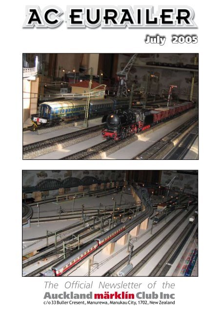
July 2005<br />
<strong>The</strong> <strong>Official</strong> <strong>Newsletter</strong> <strong>of</strong> <strong>the</strong><br />
<strong>Auckland</strong> märklín <strong>Club</strong> <strong>Inc</strong><br />
c/o 33 Buller Cresent, Manurewa, Manukau City, 1702, New Zealand
<strong>Club</strong> Officers<br />
President: Andrew Holt (09) 446 0003 AndrewH@universal.co.nz<br />
Vice President: Jim Lyne (09) 537-2177 J.GLyne@xtra.co.nz<br />
Secretary: Brendan Van Dam (09) 267 5306 bvandam@ihug.co.nz<br />
Treasurer: Brendan Van Dam (09) 267 5306 bvandam@ihug.co.nz<br />
Librarian: Warwick Harman (09) 626 5011<br />
<strong>Club</strong> Goods: Rex Meijering (09) 818 7561<br />
Editor: Steve Siegel (09) 638 4101 steve@solutionit.co.nz<br />
Custodian: Trevor Holt 0800 354 254 papercut@xtra.co.nz<br />
Next <strong>Club</strong> Meeting<br />
Location: <strong>Club</strong>rooms,<br />
58 Victoria Street, Onehunga<br />
Date: Monday, 11th July 2005<br />
Time: 19:30<br />
Topic: We will be Tinkering with Trains,<br />
so please do bring your favourite<br />
Lok, be it Digital or Analogue!<br />
<strong>Club</strong>room Activity<br />
Regular times for <strong>Club</strong>room Activity’s<br />
Second Saturday after <strong>Club</strong> night at 13:00hrs<br />
23rd July 2005<br />
Please note that <strong>the</strong> roller door is generally left down unless <strong>the</strong>re is regular traffic,<br />
As long as you see a car parked outside please knock - bang - rattle <strong>the</strong> door to<br />
attract <strong>the</strong> attention <strong>of</strong> someone inside.<br />
2
President’s Report<br />
This month I want to start by saying<br />
thank you to <strong>the</strong> members who have<br />
given <strong>of</strong> <strong>the</strong>ir time and materials to <strong>the</strong><br />
club over <strong>the</strong> years. Thank you for those<br />
who have turned up on Saturdays to help<br />
move <strong>the</strong> club layout<br />
on a bit fur<strong>the</strong>r. Thank you to those<br />
who have volunteered for <strong>the</strong> exhibition<br />
at Milford during <strong>the</strong> week <strong>of</strong> 11th - 17th<br />
July. Thank you for our presenters who<br />
have entertained and educated us at <strong>the</strong><br />
monthly<br />
meetings and thank you to <strong>the</strong> members<br />
who have given track, scenery materials<br />
and o<strong>the</strong>r items to <strong>the</strong> club to assist with<br />
<strong>the</strong> refurbishment<br />
<strong>of</strong> <strong>the</strong> club layouts. Thank you too to<br />
<strong>the</strong> members who have taken up <strong>of</strong>ficial<br />
roles and contribute on a monthly basis<br />
to <strong>the</strong> running <strong>of</strong> <strong>the</strong> club.<br />
<strong>The</strong> reason for mentioning <strong>the</strong><br />
voluntary help is due to <strong>the</strong> contribution<br />
<strong>the</strong>y are currently making with <strong>the</strong><br />
exhibition in Milford and <strong>the</strong> assistance<br />
rendered at <strong>the</strong> Saturday workshop.<br />
Suffice to say, you won’t recognise <strong>the</strong><br />
clubrooms . . . and it’s only half way<br />
<strong>the</strong>re.<br />
Our website is now correct again when<br />
it says you can run digital and analogue<br />
trains at <strong>the</strong> same time on <strong>the</strong> club<br />
layout, so come along and see in July . .<br />
. in fact come along with your favourite<br />
train in July, because <strong>the</strong> <strong>the</strong>me for <strong>the</strong><br />
night is going to be train running, so we<br />
want to see your trains, hear your stories<br />
and take lots <strong>of</strong> photos <strong>of</strong> <strong>the</strong> club layout<br />
and members in action. No entry without<br />
a train!<br />
<strong>The</strong> next Monday meeting is on <strong>the</strong><br />
11th July, which is also <strong>the</strong> day on which<br />
<strong>the</strong> exhibition at Milford Shopping Mall<br />
starts, right in <strong>the</strong> very centre <strong>of</strong> <strong>the</strong><br />
mall. Going from 10am to 4pm each day<br />
from Monday 11th July to Sunday 17th<br />
July, we will be on display with Maurice<br />
Handisides’ HO Layout, Reg Tyson’s HO<br />
Layout, <strong>the</strong> Holt’s Z layout along with<br />
Reg’s ride on Thomas and Reg’s friend’s<br />
British layout. If you can help out, give<br />
me a call (I will be <strong>the</strong>re every day, so<br />
you don’t need to fear that you will be<br />
left holding everything).<br />
<strong>The</strong> last thing I have left to mention is<br />
<strong>the</strong> website. Firstly we are still waiting<br />
for photos and details <strong>of</strong> <strong>the</strong> o<strong>the</strong>r<br />
members’ layouts, so get <strong>the</strong>m in to <<br />
steve@solutionit.co.nz > or<br />
< webmaster@marklin.org.nz > or bring<br />
your stuff to <strong>the</strong> clubnight. Secondly,<br />
people are starting to look at <strong>the</strong> site<br />
and as a result I have contact with 2<br />
people who are unfortunately moving<br />
out <strong>of</strong> <strong>Marklin</strong> and have items for sale .<br />
. . details once again on clubnight . . .<br />
with trains running, layout details being<br />
collected, cameras flashing, a number <strong>of</strong><br />
items for sale and ano<strong>the</strong>r little item <strong>of</strong><br />
interest up my sleeve, it’s going to be a<br />
busy night!<br />
See you <strong>the</strong>re,<br />
Andrew.<br />
Cover Photo’s<br />
Warrick Harmon’s<br />
Classic <strong>Marklin</strong> Layout<br />
Library Report<br />
<strong>Marklin</strong> Insider<br />
2/2/05 - 3/2/05<br />
<strong>Marklin</strong> Magazine<br />
April/May and June/July 05<br />
3
4<br />
Excerpt from an anonymous author via <strong>the</strong> internet.<br />
A Digital Introduction.<br />
<strong>The</strong> following provides a<br />
description <strong>of</strong> <strong>the</strong> components<br />
required for basic Märklin digital<br />
train operation. It assumes model<br />
numbers and equipment at <strong>the</strong> time<br />
<strong>of</strong> writing (January 2002), and is<br />
provided as a means for gaining a<br />
basic understanding <strong>of</strong> <strong>the</strong> various<br />
components available from Märklin. At<br />
this stage, no attempt has been made<br />
to include or describe substitute digital<br />
components manufactured by o<strong>the</strong>r<br />
companies.<br />
What is Märklin Digital ?<br />
Simply put, Märklin Digital <strong>of</strong>fers<br />
a way <strong>of</strong> controlling everything on a<br />
model train layout digitally, using state<br />
<strong>of</strong> <strong>the</strong> art integrated circuitry. <strong>The</strong><br />
benefits include less wiring, greater<br />
realism, and <strong>the</strong> ability to control<br />
many special effects - such as train<br />
whistles and smoke generators - at<br />
<strong>the</strong> press <strong>of</strong> a button. It consolidates<br />
all previous technologies required to<br />
realise <strong>the</strong> full potential <strong>of</strong> a train<br />
layout into one standard system.<br />
Which Type <strong>of</strong> HO Track to Use ?<br />
Märklin C, M and K track all work<br />
with Märklin Digital. However, from<br />
2001 M track is no longer being<br />
manufactured. C track, being <strong>the</strong><br />
latest, <strong>of</strong>fers a number <strong>of</strong> advantages<br />
over K track including <strong>the</strong> ability for<br />
turnout decoders to be housed within<br />
<strong>the</strong> track itself. In this arrangement<br />
<strong>the</strong>re is no additional wiring required<br />
for <strong>the</strong> remote switching <strong>of</strong> turnouts.<br />
All signals are received from <strong>the</strong> same<br />
brown and red wires which provide <strong>the</strong><br />
layout with power.<br />
A Word on Locomotives<br />
<strong>The</strong> latest digital locomotives from<br />
Märklin are electronic masterpieces.<br />
Functions such as sound effects and<br />
lights can be controlled via <strong>the</strong> Control<br />
Unit independent from locomotive<br />
motion. For example, lights and<br />
smoke generators can be switched<br />
on and <strong>of</strong>f even when <strong>the</strong> locomotive<br />
is stationary. <strong>The</strong> latest locomotives<br />
contain propulsion units which include<br />
<strong>the</strong> means to set speed parameters<br />
such as acceleration and deceleration<br />
delay, and top speed. <strong>The</strong> ability to<br />
accurately model real life locomotive<br />
motion and prototypical speeds has<br />
never been more easily achievable,<br />
and adds a level realism to locomotive<br />
operation which is truly outstanding<br />
and fun to operate.<br />
Delta locomotives will run perfectly<br />
well on a digital layout but <strong>the</strong><br />
difference between Delta and Digital<br />
locomotives (with respect to <strong>the</strong><br />
additional functionality <strong>of</strong> Digital<br />
locomotives) is considerable.<br />
Conventional (pre-digital/delta)<br />
locomotives will run correctly only<br />
if <strong>the</strong>y are retr<strong>of</strong>itted with a digital<br />
decoder.<br />
^ 6647<br />
or<br />
^ 6002
Digital Components<br />
1. <strong>The</strong> Transformer<br />
As with all train layouts, a<br />
Transformer is required to provide<br />
power to <strong>the</strong> layout from a<br />
conventional household power outlet.<br />
In a Märklin digital layout, however,<br />
<strong>the</strong> Transformer is not connected<br />
directly to <strong>the</strong> track but is connected<br />
to <strong>the</strong> Control Unit (see below) which<br />
in turn is connected to <strong>the</strong> track.<br />
<strong>The</strong> black accessory Transformer such<br />
as <strong>the</strong> model 6002 pictured above<br />
provides 52 VA and caters easily for<br />
<strong>the</strong> additional power requirements <strong>of</strong><br />
<strong>the</strong> Control Unit and o<strong>the</strong>r accessories.<br />
However, any conventional Märklin<br />
Transformer such as <strong>the</strong> white Model<br />
6647 pictured above and included in<br />
most starter kits can be used. In this<br />
configuration <strong>the</strong> speed dial becomes<br />
inactive (speed is controlled via <strong>the</strong><br />
digital Control Unit - see below). If<br />
you’re starting from scratch <strong>the</strong> more<br />
powerful ‘black’ series will provide for<br />
some expansion in <strong>the</strong> future.<br />
Only one Transformer is required to<br />
get started but as <strong>the</strong> size <strong>of</strong> a layout<br />
increases, additional Transformers may<br />
be required to cater for increasing<br />
numbers <strong>of</strong> locomotives<br />
and accessories<br />
(see below for more details).<br />
^ 6021<br />
2. <strong>The</strong> Control Unit<br />
<strong>The</strong> “computerlike”<br />
Control Unit<br />
is <strong>the</strong> nerve centre<br />
<strong>of</strong> every Märklin<br />
digital layout. It<br />
provides <strong>the</strong> ‘brains’<br />
behind controlling<br />
locomotives and<br />
accessories and is<br />
<strong>the</strong> first and basic required piece <strong>of</strong><br />
equipment (aside from a Transformer).<br />
It is also provides <strong>the</strong> point at which<br />
wires are connected to <strong>the</strong> layout.<br />
In <strong>the</strong> first instance you use <strong>the</strong><br />
Control Unit to “drive your train”,<br />
and just like a conventional Märklin<br />
Transformer it has a dial which is used<br />
to accomplish this. In fact <strong>the</strong> Control<br />
Unit provides <strong>the</strong> means by which you<br />
can independently set <strong>the</strong> speed and<br />
direction for up to 80 locomotives<br />
and control associated functions such<br />
as whistles and smoke generators.<br />
However, unlike a conventional Märklin<br />
Transformer <strong>the</strong>re is no power lead<br />
– in fact it is not a Transformer at all!<br />
You need to connect a Transformer to<br />
<strong>the</strong> Control Unit to provide it and <strong>the</strong><br />
layout with power.<br />
Apart from <strong>the</strong> speed dial, <strong>the</strong><br />
Control Unit also includes a number<br />
<strong>of</strong> buttons. Briefly, <strong>the</strong> left hand<br />
numerical buttons are used to select<br />
<strong>the</strong> locomotive you wish to control.<br />
Above <strong>the</strong> red dial are <strong>the</strong> function<br />
buttons which are used to activate<br />
additional functions on <strong>the</strong> locomotive<br />
(where fitted) – such as whistles and<br />
lights. <strong>The</strong>re is also an emergency stop<br />
button – if things get out <strong>of</strong> hand when<br />
operating multiple locomotives!<br />
IMPORTANT: <strong>The</strong> Control Unit<br />
itself does not provide <strong>the</strong> means to<br />
control accessories such as turnouts<br />
and signals. Although it provides <strong>the</strong><br />
interface for digital operation to<br />
<strong>the</strong> track, its onboard features only<br />
include <strong>the</strong> control <strong>of</strong> locomotives<br />
and associated functions. To control<br />
accessories such as turnouts you need<br />
ano<strong>the</strong>r digital device – <strong>the</strong> Keyboard<br />
6040.<br />
<strong>The</strong> Control Unit has ports on ei<strong>the</strong>r<br />
side (not shown) in which additional<br />
5
6<br />
digital devices, such as <strong>the</strong> Keyboard<br />
6040, are attached.<br />
NOTE: Only one Control Unit is<br />
required for any layout<br />
(regardless <strong>of</strong> size).<br />
In summing up, <strong>the</strong> Control Unit does<br />
two things:<br />
1. It acts as <strong>the</strong> interface to <strong>the</strong><br />
layout for all o<strong>the</strong>r digital control<br />
devices including <strong>the</strong> transformer.<br />
2. It provides for <strong>the</strong> control <strong>of</strong><br />
locomotives and <strong>the</strong>ir associated<br />
functions.<br />
You need both a Transformer and<br />
a Control Unit as <strong>the</strong> two basic<br />
ingredients for which to power and<br />
operate a Märklin digital layout. <strong>The</strong><br />
Transformer provides power to <strong>the</strong><br />
Control Unit which in turn is connected<br />
to <strong>the</strong> layout through <strong>the</strong> conventional<br />
brown and red wires. (Of course you<br />
also need at least one locomotive<br />
capable <strong>of</strong> digital operation). <strong>The</strong><br />
following pictures represent <strong>the</strong> basic<br />
requirements: (NOTE: Transformers<br />
are connected to <strong>the</strong> Control Unit via<br />
brown and yellow wires – not shown).<br />
Remember, in <strong>the</strong> second <strong>of</strong> <strong>the</strong>se<br />
two possible scenarios, <strong>the</strong> red dial<br />
on <strong>the</strong> white Transformer is inactive.<br />
<strong>The</strong> Transformer is being used only to<br />
provide power to <strong>the</strong> Control Unit.<br />
^ 6021 ^ 6002<br />
or<br />
^ 6021 ^ 6647<br />
3. Controlling Accessories<br />
<strong>The</strong> Keyboard<br />
Of course virtually every accessory<br />
from turnouts to signals can be<br />
controlled digitally. As a logical next<br />
step in expanding any layout, turnouts<br />
can be modified to allow remote<br />
switching using <strong>the</strong> Keyboard 6040.<br />
This device allows <strong>the</strong> switching <strong>of</strong><br />
16 turnouts, but can also be used to<br />
control signals and o<strong>the</strong>r solenoid<br />
activated devices.<br />
Additional keyboards can be added to<br />
provide control <strong>of</strong> up<br />
to 256 accessories<br />
through one Control<br />
Unit.<br />
Toge<strong>the</strong>r with <strong>the</strong><br />
Keyboard, you also<br />
need a digital decoder<br />
which is connected<br />
to <strong>the</strong> accessory<br />
^ 6040 Keyboard<br />
and <strong>the</strong>re are a<br />
number <strong>of</strong> options<br />
to choose from including decoders<br />
which can handle 4 accessories. <strong>The</strong><br />
digital decoder translates instructions<br />
from <strong>the</strong> Control Unit and acts as <strong>the</strong><br />
interface between <strong>the</strong> digital Control<br />
Unit and <strong>the</strong> solenoid. In <strong>the</strong> case <strong>of</strong><br />
C track turnouts, a specially designed<br />
decoder is available which can be<br />
attached directly to <strong>the</strong> solenoid under<br />
<strong>the</strong> track eliminating <strong>the</strong> need for
external wiring. <strong>The</strong> decoder receives<br />
instructions via connections to <strong>the</strong><br />
track. <strong>The</strong> same red and brown wires<br />
which provide power to <strong>the</strong> layout<br />
also provide digital information. This<br />
effectively means that you only have<br />
two wires connected to <strong>the</strong> entire<br />
layout!<br />
Keyboards attach directly to <strong>the</strong><br />
Control Unit via a port on <strong>the</strong> left<br />
hand side <strong>of</strong> <strong>the</strong> Control Unit. So a<br />
basic digital system which includes a<br />
Keyboard for accessory control looks<br />
like this:<br />
^ 6040 Keyboard ^ 6021<br />
^ 6002<br />
4. Additional Train Control<br />
While <strong>the</strong> Control Unit provides<br />
independent control <strong>of</strong> up to 80<br />
locomotives, only one locomotive<br />
at a time can be controlled via <strong>the</strong><br />
speed dial. If you select a different<br />
locomotive, <strong>the</strong> previously selected<br />
locomotive continues running at <strong>the</strong><br />
speed it was set to. If you want to<br />
simultaneously control more than one<br />
train, or if you want to provide control<br />
for o<strong>the</strong>r people around <strong>the</strong> layout,<br />
you need to add one<br />
or more Control 80<br />
f units. <strong>The</strong> Control<br />
80 f attaches to <strong>the</strong><br />
right hand side <strong>of</strong> <strong>the</strong><br />
Control Unit, but can<br />
be placed anywhere<br />
around <strong>the</strong> layout<br />
and connected to <strong>the</strong><br />
^ 6036 Control 80f<br />
Control Unit via an<br />
extension cable. Multiple Control 80<br />
f units can be attached side by side.<br />
Despite <strong>the</strong> similarity in appearance,<br />
<strong>the</strong> Control 80 f is not <strong>the</strong> same as <strong>the</strong><br />
primary Control Unit and <strong>the</strong> two are<br />
not interchangeable.<br />
5. Additional Power<br />
As a layout grows, so does <strong>the</strong><br />
requirements for power increase and<br />
additional Transformers need to be<br />
added. Under most circumstances<br />
this is accomplished through isolating<br />
sections <strong>of</strong> <strong>the</strong> track - similar to<br />
conventional non-digital layouts.<br />
In a digital layout, however,<br />
Transformers are attached to <strong>the</strong>se<br />
new sections via a Booster which is<br />
also connected to <strong>the</strong> Control Unit<br />
via an interface cable. <strong>The</strong> Booster<br />
provides <strong>the</strong> interface between<br />
<strong>the</strong> Transformer and <strong>the</strong> layout<br />
but also ‘boosts’ <strong>the</strong> digital signals<br />
from <strong>the</strong> Control Unit.<br />
In a digital layout you need a Booster<br />
for each additional Transformer.<br />
<strong>The</strong> Transformer is connected to <strong>the</strong><br />
^ 6017 Booster ^ 6002<br />
Booster via brown and yellow wires<br />
(not shown), and <strong>the</strong> Booster in turn<br />
connects to <strong>the</strong> track section via red<br />
and brown wires. <strong>The</strong> Booster is also<br />
connected to <strong>the</strong> Control Unit via an<br />
interface cable. Additional Boosters<br />
are attached to each o<strong>the</strong>r to receive<br />
digital information, so that while<br />
7
8<br />
you may have many Transformers<br />
and Boosters, you only ever have<br />
ONE Control Unit. In particularly<br />
large layouts which use many Digital<br />
input devices (Keyboards and <strong>the</strong><br />
like), a dedicated Transformer may<br />
be required to power <strong>the</strong> Control<br />
Unit and Keyboards or an array <strong>of</strong><br />
decoders. In this scenario, <strong>the</strong> Control<br />
Unit is not connected to any section<br />
<strong>of</strong> track – instead, Boosters are used<br />
to “power” individual sections <strong>of</strong> <strong>the</strong><br />
layout – taking <strong>the</strong>ir signal from <strong>the</strong><br />
Control Unit via <strong>the</strong> interface cable.<br />
See <strong>the</strong> connection examples at<br />
<strong>the</strong> bottom <strong>of</strong> <strong>the</strong> page for a clearer<br />
picture on connecting additional<br />
Transformers and Boosters.<br />
6. Automation<br />
<strong>The</strong> beauty <strong>of</strong> a digital system is<br />
<strong>the</strong> capability for true computerised<br />
and automated route control. This is<br />
primarily achieved in two ways:<br />
(a) <strong>The</strong> Memory<br />
Unit 6043 can store<br />
24 routes each<br />
with 20 turnouts<br />
or signals. You<br />
pre-program <strong>the</strong><br />
settings for up to 20<br />
^ 6043 Memory Unit<br />
accessories and at<br />
<strong>the</strong> push <strong>of</strong> a button<br />
<strong>the</strong> route is automatically set. As with<br />
<strong>the</strong> Keyboard, additional Memory units<br />
can “piggy backed” toge<strong>the</strong>r.<br />
(b) <strong>The</strong> Computer Interface 6051<br />
allows control <strong>of</strong> <strong>the</strong> entire layout<br />
via a personal computer for complete<br />
automation. S<strong>of</strong>tware is available from<br />
Märklin, and from a host <strong>of</strong> developers<br />
both freeware and o<strong>the</strong>rwise on <strong>the</strong><br />
internet. Practically every aspect <strong>of</strong><br />
digital train and layout operation can<br />
be accomplished through a computer,<br />
and <strong>the</strong>refore <strong>the</strong> Interface can be<br />
a cost effective alternative to <strong>the</strong><br />
purchase <strong>of</strong> Keyboard and Memory<br />
units for those who are “computer<br />
savvy”.<br />
7. Decoders<br />
^ 6051 Interface<br />
<strong>The</strong> digital devices discussed so far<br />
represent <strong>the</strong> “input” side <strong>of</strong> <strong>the</strong><br />
digital layout. At <strong>the</strong> o<strong>the</strong>r end - where<br />
all <strong>the</strong> action takes place - we need a<br />
decoder to ‘translate’ <strong>the</strong> instructions<br />
from <strong>the</strong>se input devices. <strong>The</strong>re are<br />
a variety <strong>of</strong> decoders available which<br />
perform a number <strong>of</strong> functions. <strong>The</strong>re<br />
are decoders which can be installed<br />
into older locomotives for operation on<br />
a digital layout, as well as a plethora<br />
<strong>of</strong> decoders for accessories such as<br />
turnouts and signals. Needless to say,<br />
almost every locomotive and accessory<br />
can be controlled digitally. Here are<br />
some examples.<br />
^ K83 ^ K84 ^ S88<br />
C Track turnout fitted ^<br />
with solenoid and decoder<br />
^ 60901 High-Efficiency Propulsion set.
A WORD OF WARNING: In a digital<br />
system, constant voltage is supplied<br />
to <strong>the</strong> track. Older locomotives which<br />
have not been modified will run at a<br />
constant speed in one direction only<br />
Connection Examples<br />
<strong>The</strong> following diagrams illustrate<br />
basic device connection with <strong>the</strong><br />
exception <strong>of</strong> accessory decoders. <strong>The</strong><br />
coloured lines represent wires which<br />
connect <strong>the</strong> primary devices and <strong>the</strong><br />
track.<br />
(a) To <strong>the</strong> right a simple layout with<br />
one Transformer, one Keyboard and <strong>the</strong><br />
obligatory Control Unit. Only one set<br />
<strong>of</strong> track wires is required to provide<br />
<strong>the</strong> layout with power and digital<br />
information. As <strong>the</strong> layout grows an<br />
additional set <strong>of</strong> feeder wires should<br />
be used to provide power to <strong>the</strong> o<strong>the</strong>r<br />
side <strong>of</strong> <strong>the</strong> track.<br />
Transformer Booster<br />
2<br />
Transformer Keyboard Control Unit<br />
(b) Below a more complex layout<br />
with two Transformers, Memory,<br />
two Keyboards and a Control 80 f.<br />
<strong>The</strong> Control Unit is connected to <strong>the</strong><br />
Booster via an interface cable (blue).<br />
<strong>The</strong> two track sections are electrically<br />
isolated from each o<strong>the</strong>r.<br />
<strong>The</strong>se older examples <strong>of</strong> <strong>the</strong> digital<br />
system have now been fairly much<br />
superceded by <strong>the</strong> newer <strong>Marklin</strong><br />
systems “Mobile Station” and even<br />
newer “Central Station”.<br />
You can read about <strong>the</strong>se in <strong>the</strong> April<br />
05 issue <strong>of</strong> AC Eurailer.<br />
Transformer Memory Keyboard Keyboard Control Unit Control 80f<br />
1<br />
9
10<br />
Reprinted with permission <strong>of</strong> Wolfgang Meyenberg, visit his website at www.sh1.org<br />
<strong>The</strong> HP Signal System<br />
<strong>The</strong> Hp system was tested by <strong>the</strong><br />
Deutsche Reichsbahn in 1928 and<br />
introduced into <strong>the</strong> Signalbuch (signal<br />
code) in 1935, however few colour<br />
light signals were erected before <strong>the</strong><br />
end <strong>of</strong> Word War II. <strong>The</strong> main usage<br />
was and is in West Germany.<br />
<strong>The</strong> aspects are <strong>the</strong> same as <strong>the</strong><br />
night aspects <strong>of</strong> <strong>the</strong> Semaphore<br />
Signals. Its signals consist <strong>of</strong> home<br />
signals which are at least capable<br />
<strong>of</strong> indicating “stop” and “clear”.<br />
<strong>The</strong> home signals (Hauptsignal) may<br />
show “line clear with medium speed”<br />
as well as some o<strong>the</strong>r aspects like<br />
“stop, shunting permitted” or give<br />
an indication <strong>of</strong> what speed exactly<br />
is allowed (by a speed indicator Zs3).<br />
At 400 m - 1000 m before <strong>the</strong> home<br />
signal, a distant signal (Vorsignal) is<br />
showing <strong>the</strong> aspect <strong>the</strong> driver has<br />
to expect at <strong>the</strong> home signal. If <strong>the</strong><br />
visibility is limited, additional distant<br />
signal repeaters (Vorsignalwiederholer)<br />
may be used.<br />
If <strong>the</strong> block length is about 1000 m,<br />
<strong>the</strong> position for <strong>the</strong> distant signal for<br />
<strong>the</strong> home signal in advance comes<br />
close to <strong>the</strong> position <strong>of</strong> <strong>the</strong> home signal<br />
in rear. In this case, <strong>the</strong> distant for<br />
<strong>the</strong> home signal in advance is usually<br />
mounted at <strong>the</strong> post <strong>of</strong> <strong>the</strong> home signal<br />
in rear, you will find this <strong>of</strong>ten with<br />
entrance signals.<br />
Signal Heads<br />
<strong>The</strong>re are different signal heads in<br />
use, depending on <strong>the</strong> supplier and/or<br />
<strong>the</strong> aspects that are to be displayed.<br />
<strong>The</strong>se heads vary slightly in shape<br />
(corners may be angled or not) and in<br />
<strong>the</strong> arrangement <strong>of</strong> lamps. <strong>The</strong> signal<br />
indication does not depend on where<br />
in <strong>the</strong> head <strong>the</strong> lamp is placed.<br />
Here are some examples:<br />
1 2 3 4 5<br />
1 This one can just say ‘clear’ or ‘stop’, usually used<br />
with block signals.<br />
2 This one can also display ‘clear with 40 km/h’, <strong>the</strong><br />
lower red is an emergency red which lights if <strong>the</strong> ‘main’<br />
red fails.<br />
3 & 4 <strong>The</strong>se two can display <strong>the</strong> (now obsolete)<br />
‘double-red’ Hp00 as well as ‘shunting permitted’, this<br />
is most probably an exit signal.<br />
5 This is a compact head equipped with additional<br />
lamps.<br />
Exit Signals<br />
Exit signals are placed at <strong>the</strong> end <strong>of</strong><br />
each track. Especially in stations with<br />
curved tracks <strong>the</strong> exit signals must be<br />
placed in a line that crosses <strong>the</strong> tracks<br />
ei<strong>the</strong>r perpendicularly or diagonally,<br />
so that <strong>the</strong> signals appear in <strong>the</strong><br />
same order, regardless <strong>of</strong> where <strong>the</strong><br />
viewpoint is. On branch lines <strong>the</strong> exit<br />
signals may be omitted when <strong>the</strong> exit<br />
speed does not exceed 60 km/h.<br />
To maximise <strong>the</strong> usable track length<br />
in a station, <strong>the</strong> signals should be<br />
placed as far as possible to <strong>the</strong> point<br />
area. On converging tracks however,<br />
since <strong>the</strong> signals also protect <strong>the</strong><br />
following point(s) and movements<br />
on <strong>the</strong> o<strong>the</strong>r tracks, <strong>the</strong>re must be<br />
sufficient distance between <strong>the</strong> exit<br />
signal and adjacent points or o<strong>the</strong>r<br />
tracks.<br />
On freight yards or freight tracks<br />
Group Exit Signals may be used. This<br />
is a single signal placed after <strong>the</strong><br />
last point where all tracks it governs
join. Additionally at <strong>the</strong> end <strong>of</strong> each<br />
individual track a high line-close signal<br />
(Sh 0/1) is placed to be able to show<br />
which track exactly is cleared with <strong>the</strong><br />
group exit signal.<br />
Please note that a clear exit signal<br />
does NOT permit a halting train to<br />
depart - this is accomplished by <strong>the</strong><br />
departure order signal.<br />
Home Signal Aspects<br />
1 2 3 4 5<br />
1 Hp 1: line clear (with timetable speed)<br />
2 Hp 2: line clear with slow speed<br />
(40 km/h if not indicated o<strong>the</strong>rwise)<br />
3 & 4 Hp 0: stop*<br />
5 Hp 0 + Sh 1: stop, shunting permitted<br />
1<br />
Distant Signal Aspects<br />
2<br />
1 Vr 1: expect clear<br />
2 Vr 2: expect clear with medium speed<br />
3 Vr 0: caution, expect stop<br />
4 distant signal repeater or home signal at reduced<br />
* For <strong>the</strong> double-red aspect, see<br />
peculiarities. For <strong>the</strong> rules applying to a signal<br />
showing Hp 0-stop or at failed signal see also<br />
post plates.<br />
Peculiarities<br />
<strong>The</strong> Hp 00 aspect<br />
That <strong>the</strong>re are two aspects for ‘Stop’<br />
pertains to <strong>the</strong> fact that in older rule<br />
books (Signalbuch), <strong>the</strong> signal Hp 0<br />
(a single red light) meant ‘stop for<br />
train movements’, but shunting<br />
movements were to completely ignore<br />
this signal. So a new aspect Hp 00<br />
3<br />
4<br />
(two reds) was introduced meaning<br />
‘stop for train and shunting<br />
movements’ while Hp 0 (a single<br />
red light) meant ‘stop for train<br />
movements, shunting movements<br />
ignore this signal’.<br />
Later it was felt that a red light<br />
should be a red light, i.e. red should<br />
equal stop always. (Note this is<br />
opposed to <strong>the</strong> U.S. practice <strong>of</strong> “If<br />
it’s not all red, it’s not red at all”,<br />
see page “do American signals make<br />
sense?”) So <strong>the</strong> meaning was changed<br />
according to this: A red light (Hp 0)<br />
was stop for everyone. Hp 0+Sh 1<br />
(red + two whites) was used to say<br />
“stop, shunting permitted”. As you<br />
might expect, <strong>the</strong> second red lamp<br />
was obolete by now. As you might<br />
also expect, one could simply remove<br />
that bulb. But alas! <strong>The</strong> signals are<br />
wired such that <strong>the</strong> failure <strong>of</strong> a lamp<br />
is detected (which does make me<br />
feel much safer riding trains!), so you<br />
would have to re-wire <strong>the</strong> security<br />
equipment at <strong>the</strong> signal boxes. Since<br />
that would have become too expensive<br />
it was considered covering <strong>the</strong> second<br />
light with adpesive tape (no kidding!).<br />
But, smart as we Germans are, we<br />
found a way much better: <strong>The</strong> signal<br />
book states that <strong>the</strong> signal aspect Hp<br />
0 (stop) is “one red light or two red<br />
lights arranged horizontally”.<br />
<strong>The</strong> German Question<br />
(This expression was used before<br />
1990 in Germany for <strong>the</strong> Division <strong>of</strong><br />
<strong>the</strong> country.) As with railways, until<br />
now <strong>the</strong>re still exist two Signalbücher<br />
(Rule Books). Since some things have<br />
really developed differently, that is<br />
understandable, but <strong>the</strong>re are some<br />
o<strong>the</strong>r things that are so different<br />
that you wouldn’t imagine, so I shall<br />
present a few quotes here. In <strong>the</strong><br />
11
text below are <strong>the</strong> DB (West) and<br />
<strong>the</strong> corresponding DR (East) text, <strong>the</strong><br />
differences are Highlighted.<br />
Description <strong>of</strong> semaphore aspect<br />
Hp 0 (stop)<br />
DB A signal arm - on two-armed<br />
signals <strong>the</strong> upper arm - points<br />
horizontally to <strong>the</strong> right.<br />
DR <strong>The</strong> signal arm - on twoarmed<br />
signals <strong>the</strong> upper arm - points<br />
horizontally to <strong>the</strong> right.<br />
Description <strong>of</strong> semaphore aspect Vr 2<br />
(expect clear)<br />
DB <strong>The</strong> round disc lies horizontally<br />
[flipped backwards]. Where a wing<br />
is present, it points straightly<br />
downwards.<br />
DR <strong>The</strong> round disc lies horizontally<br />
[flipped backwards]. <strong>The</strong> wing points<br />
straightly downwards.<br />
Description <strong>of</strong> speed reduction signal<br />
board Zs 3<br />
DB A white digit on a black<br />
triangular board with a white border.<br />
DR A white number on a black<br />
triangular board with a white border.<br />
Description <strong>of</strong> Lf 3 board<br />
(end <strong>of</strong> speed restriction)<br />
DB A rectangular white board<br />
showing a black “E” standing on <strong>the</strong><br />
shorter edge.<br />
DR A rectangular white board<br />
showing a black “E”. [note: this one<br />
also stands on <strong>the</strong> shorter edge...]<br />
Post Plates<br />
Post plates determine <strong>the</strong> rules that<br />
apply when a signal has failed. Most<br />
signals carry a post plate mounted on<br />
<strong>the</strong> signals post below <strong>the</strong> signal head<br />
Home Signal Post Plates.<br />
1 2 3 4 5 6<br />
1 Train movements may pass a stop signal at danger<br />
or a defective home signal only if aspect Zs 1, Zs 7, or<br />
Zs 8 is displayed, or signalman hands over or dictates<br />
a written permission to do so. Shunting movements<br />
may pass it by a verbal permission. Used for entrance,<br />
exit, and protecting signals, or automatic block signals<br />
covering level crossings or sidings.<br />
2 Same procedure as post plate white-red-white. But if<br />
driver is unable to communicate with signalman, train<br />
may pass <strong>the</strong> signal and may proceed on sight until<br />
next home signal. Used for automatic block signals.<br />
3 This post plate is used in two regions, where it<br />
has different meanings: In Berlin only: Urban railway<br />
lines for some entrance or exit signals on lines with<br />
automatic block equipment. Same procedure as post<br />
plate white-red-white, but after train has obtained<br />
signalman’s permission to pass <strong>the</strong> signal (or after<br />
aspect Zs 1 was cleared) train must proceed on sight<br />
until next home signal. Shunting movements may pass<br />
it by a verbal permission when at danger or defective.<br />
On <strong>the</strong> Augsburg-Donauwörth line only: Identifies a Sk<br />
home signal.<br />
4 Used only on Berlin and Hamburg urban railway<br />
lines for automatic block signals. Combined Signal is<br />
permissive, train may pass it without permission when<br />
at danger or defective. Proceeding on sight applies<br />
until next home signal.<br />
5 Train movements may pass <strong>the</strong> protecting signal<br />
at danger only if signalman hands over or dictates<br />
a written permission. Extinct protecting signals are<br />
not valid for train movements. Shunting movements<br />
may pass it by a verbal permission when at danger or<br />
defective.<br />
6 M-Board. Used on signals with white-red-white<br />
white-yellow or red post plate. Train may pass a home<br />
signal at danger or a defective home signal also by a<br />
verbal order <strong>of</strong> <strong>the</strong> signalman to prevent delays.<br />
© Wolfgang Meyenberg