The Auckland Märklin Club Inc - The Auckland Marklin Club Inc
The Auckland Märklin Club Inc - The Auckland Marklin Club Inc
The Auckland Märklin Club Inc - The Auckland Marklin Club Inc

Create successful ePaper yourself
Turn your PDF publications into a flip-book with our unique Google optimized e-Paper software.
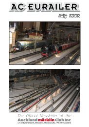
<strong>The</strong> <strong>Auckland</strong> <strong>Märklin</strong> <strong>Club</strong> <strong>Inc</strong><br />
Special Interest Group<br />
1220 mm x 610 mm Module Specifications.<br />
This specification defines a module that is 1220 ± 2 mm long and 610 mm wide at the ends.<br />
(<strong>The</strong>se specifications are loosely based on the ETE Module specifications and the ETE Great Lakes C<br />
track module specifications written mainly by Daniel Roe, visit < www.ete.org > for more information)<br />
Purpose:<br />
<strong>The</strong> purpose of this specification is to define the construction of modules with a European (all of Europe)<br />
theme with the intent of attaching them together for the purpose of entertaining people and to have some<br />
fun. If you’re into completely prototypical operation these modules may well lead to disappointment. On<br />
the other hand, if you’re into having some fun and entertaining people with the idea of encouraging them<br />
to join in the fun and the club. Also, if you have some completely crazy idea for a module that breaks all<br />
the rules, tell us about it first – rules are meant to be broken.<br />
Definitions:<br />
• Left and right are defined from the perspective of the operator inside the layout while viewing the<br />
module from the top, i.e. the side with the track on it.<br />
• Approximately means just that. We’re not all genius woodworkers – do your best.<br />
• “Entertaining people” means that after they see the layout, they walk away smiling, happier than when<br />
they came.<br />
• “Having fun” means we don’t have any “epoch police”, nor encourage “rivet counters”, nor do we try to<br />
advance any political or other personal agendas.<br />
• Roadbed – the builder supplied ballasted area beside the trackbed. This is NOT the plastic ballast<br />
attached to the <strong>Märklin</strong> supplied track.<br />
• Trackbed – the “ballast looking” piece permanently attached to the track supplied by <strong>Märklin</strong>.<br />
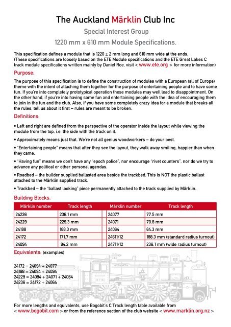
Building Blocks:<br />
<strong>Märklin</strong> number Track length <strong>Märklin</strong> number Track length<br />
24236 236.1 mm 24077 77.5 mm<br />
24229 229.3 mm 24071 70.8 mm<br />
24188 188.3 mm 24064 64.3 mm<br />
24172 171.7 mm 24611/12 188.3 mm (standard radius turnout)<br />
24094 94.2 mm 24711/12 236.1 mm (wide radius turnout)<br />
Equivalents: (examples)<br />
24172 = 24094 + 24077<br />
24188 = 24094 + 24094<br />
24229 = 24094 + 24071 + 24064<br />
24236 = 24172 + 24064<br />
For more lengths and equivalents, use Bogobit’s C Track length table available from<br />
< www.bogobit.com > or from the reference section of the club website < www.marklin.org.nz >
Module Specification<br />
Group Standards:<br />
One of the items that we felt was most important was the development and use of standards within our<br />
group. While not wanting to stifle individual creativity, we wanted to have a unified look to the modules,<br />
operational reliability, and total compatibility for the group. Toward that end the following “overall”<br />
standards have been set:<br />
• A standard module end piece profile, based upon the ETE standard < www.ete.org > with both up<br />
and down elevations was developed. It was felt that this helped to get away from the flat table-top look<br />
so many other modules have. While individual modules may transition up or down from this profile, all<br />
modules must adhere to the end profile at the point where they join the next module. See Benchwork<br />
section.<br />
• <strong>The</strong> modules are secured to each other by 2 x 45mm x 8mm hex bolts (or “bedhead” bolts) with “knock-innuts”<br />
inserted in the right hand inside end profile (as viewed from the “audience” side) NB: see Sheet 2. A<br />
template with standard bolting holes is used to insure that all bolting holes mate properly. See Benchwork<br />
section.<br />
• A sculptured terrain profile on the “audience” side of the module is strongly encouraged. This also<br />
helps to differentiate the modules from “flat table top” types. See Benchwork section.<br />
• All exposed wood on the modules (front/rear and end profile) is painted in a matte paint (Resene<br />
“Diesel”). This presents a very striking appearance when assembled, not only because of the uniformity,<br />
but also because only the modelled parts stand out. See Benchwork section.<br />
• Each module has skirting attached of a specified fabric attached by Velcro strips. See Benchwork<br />
section.<br />
• Direction of travel on the double track mainline is assumed to be right-handed. (i.e. the direction of<br />
travel of the line closest to you is to the right as you face the module.) See Trackwork section.<br />
• All track is to be weathered rust colour (preferably Humbrol 113). See Trackwork section.<br />
• For stability as well as uniformity, all catenary must be the new style <strong>Märklin</strong> catenary, along with<br />
<strong>Märklin</strong> wires. See Catenary section.<br />
• Wiring was developed using a 7 wire buss as a standard with a 12 point plug with redundancy for future<br />
intermodule and supermodule items eg: distance signal’s, contact tracks etc . See Wiring section.<br />
• Only Viessmann decoders must be present for operation of all mainline signals and turnouts. Not only<br />
is this is to facilitate future computer control, but also these decoders can be supplied by a separate<br />
unboostered transformer and can be addressed by external dip switches, Digital addresses will be<br />
assigned by the module group. Since solenoid operation (signals, switches, etc) and lighting consumers<br />
are required on most of the modules, each modeller is required to install at least one Viessmann<br />
decoder (5211 for solenoids etc). Exception: Modules without any switches, signals or lighting, eg:<br />
straight through lines. See Wiring section.<br />
• To make modules created by different individuals “blend”, scenery colour standards have been<br />
developed. See Appearance section.<br />
• Unsceniced, or partially sceniced modules are not allowed to display with the group at shows. See<br />
Appearance section.<br />
• All signals must be from <strong>Märklin</strong> or Viessmann and be of the below baseboard operation type, See<br />
Signalling section.<br />
Benchwork.<br />
<strong>The</strong> overall modules dimensions are 1220mm long by 610mm wide. <strong>The</strong> end pieces of all the modules<br />
have a mandatory profile Sheet 1. <strong>The</strong> up and down profiles on end pieces must be maintained, but the<br />
profile of the module may taper up or down over the run of the module. In fact is recommended that the
front and rear sideboards be cut originally higher than the end pieces, so tapered “terrain” cuts can be<br />
cut with a jigsaw front and back.<br />
<strong>The</strong> mating of the end pieces is particularly critical. For this reason, <strong>The</strong> <strong>Auckland</strong> <strong>Märklin</strong> <strong>Club</strong> <strong>Inc</strong> will<br />
supply at cost the end pieces or supply you with a paper template if required. Particular care should be<br />
taken with respect to the placement of the module mating holes, however you will be required to confirm<br />
that your module “mates” with others. Sheet 1<br />
<strong>The</strong> end pieces are made of 17mm plywood. For stability, a minimum of five vertical risers are<br />
recommended. As the module develops, these risers will be used to attach horizontal strips of either ply<br />
or mdf which will hold up the roadbed.<br />
Two horizontally mounted 42mm x 42mm mouldings provide a stable support for the leg assemblies.<br />
<strong>The</strong>se are attached to the end profiles Sheet 2 Legs are also made from 42mm x 42mm mouldings with<br />
2 x 65mm x 19mm mouldings as horizontal braces. Each leg has a 10mm by 50mm “foot” (Hettich 01186)<br />
inserted into a “knock-in-nut” (Hettich 00513) nut Sheet 3. <strong>The</strong>se “feet” provide for height adjustment on<br />
floors which are uneven. <strong>The</strong> two leg assemblies are mounted by hinges in an offset manner so that<br />
when collapsed, they fold under the skirt of the module. <strong>The</strong> leg length dimension should allow for a<br />
floor to top of rail dimension of 1000mm. When extended module legs are kept open by support blocks<br />
placed between and over the tops of the rails of the module legs. Sheet 3<br />
1 Module length.<br />
Each module should be as close to 1220 mm ± 2mm in length. <strong>The</strong> track should be exactly flush with the<br />
right and left ends. A piece of C track (number 24094) could be used on the left and the right side of the<br />
module as a guide how you fill in the difference is up to you.<br />
1220mm - 188mm = 1032mm eg: to cover this you could use 3 x 24236’s + 1 x 24229 + 1 x 24094.<br />
For more lengths and equivalents, you could use the “Bogobit” C Track length table available from<br />
< www.bogobit.com > or from the reference section of the club website < www.marklin.org.nz ><br />
2 End pieces.<br />
<strong>The</strong> end pieces can be supplied by the club, or use the spec’s included to make your own, however you<br />
will be required to confirm that your module “mates” with others.<br />
3 Module width.<br />
<strong>The</strong> modules must be 610 mm wide at their ends. Almost anything larger is allowed in between the ends,<br />
with the exception that modules should not be extended into the operator’s area. (talk to us first if you<br />
intend to do this) This does not preclude building a small shelf for the placement of control boxes or the<br />
like. Building out into the spectator’s area is allowed with the proviso that each module, or the ends of a<br />
“super” module, must start and end at the same line.<br />
4 “Super Modules”<br />
If you wish to build a “super” module made up of two or more modules, the inner interfaces between the<br />
modules are entirely up to the builder. It follows, therefore, that the length of the individual modules is<br />
also entirely up the builder as long as the whole “super” module is a multiple of 1220 mm in length and<br />
which begin and end in the same line. <strong>The</strong> overall deviation from (Overall length = N X 1220 mm) where<br />
N is the number of modules should be less than 5 mm.<br />
5 Leg support blocks.<br />
Each module owner is responsible for supplying 1 x Intermodule leg support block (1 x per module)<br />
Sheet 3, This block slips over the lower cross span of the legs and therefore holds the legs together.<br />
<strong>The</strong>y can be either attached to the underside of the module (if there is space) or attached to the inside of<br />
the transport crate.<br />
6 Transport crate.<br />
Standard and design drawings to follow shortly.
7 Perspex Protection.<br />
4mm Perspex must be attached to the front of all modules using countersunk screws (yet to be<br />
determined) there are two main reasons for this;<br />
• a If for whatever reason there is a derailment the perspex will save that expensive Lok from ending up<br />
on the floor.<br />
• b <strong>The</strong> perspex also stops the casual “touching” that so many youngsters want to do. (it’s an unfortunate<br />
fact of life that some parents don’t adequately supervise their offspring)<br />
<strong>The</strong> perspex will extend upwards, starting 40mm from the lower edge of the module to 120mm above the<br />
base grade of the module, on a standard sized module that would mean the perspex will measure 1220<br />
mm wide X 280 mm high. Sheet 5 Be sure to read Appearance section rule 5. Please also attach a strip of<br />
Velcro (preferably black), below the perspex, for the entire length of the module (the “looped” side), there<br />
is Velcro available with double sided tape on it, then screw using 7 x flatheaded screws evenly spaced,<br />
so the Velcro doesn’t tear off when removing the skirt<br />
Trackwork.<br />
<strong>The</strong> system is designed to run only <strong>Märklin</strong> compatible products. <strong>The</strong> modules consist of two main line<br />
tracks running parallel for through trains. Each main line utilises <strong>Märklin</strong> “C” track.<br />
Not coincidentally, by positioning the inside track at 250mm from the front of the module, two modules<br />
back to back can be connected by the 360 mm R1 <strong>Märklin</strong> curve. This allows back to back placement of<br />
the modules for home use, or perhaps special end curved sections could be developed in the future for<br />
setting up in very narrow locations.<br />
Trackwork Specification:<br />
1 Trackbed height.<br />
<strong>The</strong> bottom of the trackbed, the surface the “C” track sits on, shall be 1000mm off of the ground. All<br />
modules have adjustment built into the legs so that wherever we set the layout up we’ll choose one<br />
module to be the “master height” module and adjust all the others, within reason, to meet that height.<br />
2 Curves and grade elevation changes.<br />
Because each module starts with the effective length of 2 x 24094’s, the grade under this length should<br />
be flat at the specified trackbed height. We also advise caution while planning curves and gradients on<br />
the main line. While not discouraged, curves should not have a sharper radius than the corner modules<br />
R4/R5. You may need to make a “Supermodule” to incorporate R4/R5 curves, Even on the 30 o <strong>Märklin</strong><br />
standard R1 curve, long passenger cars have considerable overhang, so for aesthetic reasons mainline<br />
curves should be a minimum of R4 radius. You can use R1/R2 to branch off of the mainline if you wish.<br />
Gradients are also a problem if they’re too steep. Long trains, as are the norm on modules, are already a<br />
heavy load. <strong>The</strong>refore it is recommended track not exceed one or two percent grades.<br />
3 Mainlines.<br />
Each module shall have two mainlines spaced 64.3 mm apart which are electrically isolated. This<br />
is the “natural” spacing of the two tracks off of a 24711/12 wide radius turnout as well as the spacing<br />
between the R4 and R5 curves that we intend to use for the corner modules. Each module, or “super”<br />
module, shall be able to connect to the next module with a <strong>Märklin</strong> 24188 piece of “C” track in a manner<br />
specified in the Joiner Track section.<br />
4 Type of track.<br />
<strong>The</strong> intent of this rule is to encourage the 100% use of <strong>Märklin</strong> “C” track but not to preclude the use<br />
of <strong>Märklin</strong> “K” track. If K track is used on your module you will need to supply 4 sceniced 24922 C/K<br />
transition pieces (see Joiner Tracks). You would need to start your K track module 90mm into the<br />
module as opposed to 94mm for the C track module, also if building a K track module the track must be<br />
shimmed to the same height as the C track to avoid any “dips” in the mainlines.<br />
5 Track location.<br />
<strong>The</strong> inside track centre stud is located 250mm from the front (audience side) of the module. That means
that from the inside of the module, from the operator’s side, the first edge of the first trackbed shall be<br />
approx 345 mm out from the inside edge of the module rear. <strong>The</strong> centre-to-centre spacing to the next<br />
track out (towards the audience) shall be 64.3 mm. See the drawing, figure 1.<br />
6 Roadbed location.<br />
At the ends of the module the roadbed shall extend 12 mm out from the side of the “C” trackbed. For<br />
the module with just two mainlines this means that the roadbed would start approx, 328 mm out from<br />
the inside edge of the module and extend out to approx, 463 mm. See the drawing, figure 1. This leaves<br />
open the roadbed width inside the module to meet each builder’s own needs with the proviso that the<br />
roadbed must meet this rule, at least, under the 24188 bridge piece. <strong>The</strong> colours of the roadbed are in the<br />
Appearance section.<br />
7 Electrical connections.<br />
Prior to installing the track onto the trackbed, insure that all electrical connections to the track have<br />
been made. IMPORTANT: any joins between main lines need to be isolated for all electrical connections.<br />
Ground and Power, no exceptions!<br />
8 Switches.<br />
All switches must have 74490 turnout mechanism’s installed, also all mainline switches will require<br />
turnout lantern part number 74470, (the kit comes with 2 lanterns), for branchlines this is optional.<br />
9 Noise control.<br />
In an attempt to keep sound/noise from rolling stock to a minimum we have decided to lay the “Noch”<br />
HO Mössmer foam plastic track bedding system under the C track, this can be purchased from some<br />
Railcentric model shops eg: in <strong>Auckland</strong> from “<strong>The</strong> Model Shop” in Clark Street, New Lynn, (no website).<br />
10 Securing track.<br />
C track and the Noch roadbed can be attached to your sub-roadbed plywood/mdf with C track screws.<br />
<strong>The</strong> reason we will secure the track with screws is because these modules will be transported and as<br />
they will get knocked around we don’t want the track to fall off.<br />
11 Weathering.<br />
All track (and ties) are to be weathered rust colour (preferably Humbrol brand #113). Air brushing the<br />
track will give a more detailed look. Care should be taken to carefully clean the tops of the rails and<br />
centre studs.<br />
12 Bridge pieces.<br />
A 24188 will be used as the bridge piece between modules. This applies to both two mainlines. In other<br />
words, fasten down all of the track on your module except for the 24094.<br />
Exception – You can permanently fasten the 24094 to the module if it is used for signalling or the like<br />
you will however need to supply another sceniced 24094 track piece to make it up to 188mm, see Joiner<br />
Track section below.<br />
Joiner Tracks.<br />
64.3 mm<br />
fig 1 12mm 12mm 328mm<br />
to the rear<br />
Between module’s the joiner tracks are a standard 188 mm section of <strong>Märklin</strong> C-Track (24188) and is<br />
used to join tracks between modules. Each section of track is modified (see notes below) and then<br />
permanently affixed, (screwed) to a section of 2mm ply. Clearance of 94 mm from module end to the<br />
fixed track end allows for the installation of the 188 mm sections to create a continuous line.<br />
To “scenic” the joiner track, <strong>The</strong> 24188 needs to be attached to a piece of 2mm ply available from Hobby Shops:<br />
• A section of ply should be cut so that it is 188mm long and 62mm wide.<br />
• Screw down the C Track section, (in the centre of the 62mm wide piece of ply) then scenic as described
in the Appearance section. When the joiner track is complete upend it and “seal” the exposed ply with<br />
gloss paint (this will help the joiner to slide on the module upper when being joined together).<br />
• Remove the retaining bumps on the C track joiner (they’re the small bumps that make the C track go<br />
“click” when pressed together) this will help when it comes to disassembly time.<br />
Each module owner is responsible for providing a set of sceniced joiner sections. Joiner sections must<br />
also be provided for any local sidings like you may have on a “Supermodule”. “Supermodule” joiners may<br />
also be of a different length, made in the same manner as the 24188 joiner track.<br />
Catenary.<br />
<strong>The</strong> main lines must have overhead catenary compatible with the New <strong>Märklin</strong> catenary system. <strong>The</strong> use<br />
of non-new <strong>Märklin</strong> catenary is strongly discouraged for several reasons. Because of the transportation<br />
of the modules there is a considerable amount of “wear and tear” that the new <strong>Märklin</strong> system, because<br />
of its die cast construction is better able to withstand. Also, the new <strong>Märklin</strong> system is very prototypical<br />
in appearance, and masts and overhead wires are available for most European countries (Viessmann).<br />
Further, the new <strong>Märklin</strong> masts screw through the bench work via a slide block, for solid placement.<br />
We recommended that Swiss-prototype “zig-zag” clearances be followed to allow operation for narrow<br />
pantograph sliders found on fine scale models, so they don’t hang up inadvertently. See the <strong>Märklin</strong><br />
Catenary Handbook (item # 03902) for further clarification on this subject.<br />
1 <strong>The</strong> catenary masts.<br />
<strong>Märklin</strong> compatible masts must be installed at the very minimum on the two mainlines. Two feeder<br />
masts must also be in place somewhere on the module. When the rule says “beyond” it means towards<br />
the center of the module. Four masts MUST be installed on the two mainline tracks, 180mm beyond the<br />
module interface to the outside world. <strong>The</strong> masts should be installed on the outside of the mainline (only<br />
on the inside when necessary ie: for some turnouts).<br />
NB: <strong>The</strong> distance from centre stud to mast centre is usually 34mm. see figure 2<br />
fig 2<br />
2 <strong>The</strong> catenary wires.<br />
A standard <strong>Märklin</strong> catenary wire (item number 70360) will be used to bridge the gap between two<br />
modules. (you will be required to suppy two pieces as joiners) Any wire length can be used in the<br />
interior of the module (remembering of course that a 360mm gap between masts is more prototypical).<br />
It is absolutely essential that the wires be placed above the centre of any track. <strong>Märklin</strong> catenary wire<br />
should be used. A good rule of thumb would be that the catenary wire must be at least 2 mm away from<br />
the inside of any rail (use the special adjustment jigs from <strong>Märklin</strong>). Special attention to this detail is<br />
required at any turnout or crossing. <strong>The</strong> height of the wire above the track is determined by the special<br />
<strong>Märklin</strong> jig (usually about 67mm from the top of the track to the underside of the wire).<br />
• It is up to the individual as to whether or not they put catenary over their branchlines.
• <strong>The</strong> catenary will be connected to the main wiring buss (it may or may not be used in the future) but<br />
please ensure there is electrical continuity across your module.<br />
• NB: <strong>The</strong> <strong>Märklin</strong> catenary is fully functional without modification.<br />
• In all likely hood any analogue E Loks should have their sliders removed (as recommended by <strong>Märklin</strong>)<br />
to use the Catenary as it will have non-digital operating characteristics.<br />
Wiring.<br />
A separate electrical buss system is probably not absolutely needed when using <strong>Märklin</strong> “C” track. In<br />
the <strong>Märklin</strong> Insider Digital Book, it says that larger layouts require a separate buss so our system uses a<br />
separate buss system this to improve reliability and to facilitate unique wiring requirements. <strong>The</strong> wiring<br />
system is designed to accommodate only AC 3-Rail, <strong>Märklin</strong> (Motorola) Digital and also be compatible<br />
with “<strong>Märklin</strong> Systems” controllers (not the Mobile Station unless connected via a CS) We will also have<br />
the ability to run part of the layout in “analogue” mode. Each module or “supermodule” must have one<br />
connection point for the “Control Desk” (located at the rear or “operator”side, extending 300mm from<br />
the rear of the module and wired the same as the interconnection male plug), this gives us the ability<br />
to locate the “Control Desk” almost anywhere within the operational area. We will be using Viessmann<br />
Decoders as they can be supplied by a separate transformer and have no need to be “Boostered” as<br />
the <strong>Märklin</strong> K83/84’s do (less cost, more reliability). At the “Control Desk” the Earth wires will be joined<br />
except when In “Analogue” mode where a switch will break that line.<br />
1 <strong>The</strong> Buss.<br />
<strong>The</strong> buss consists of seven wires running the entire length of each 1220 mm module. A 7 wire buss<br />
connects the modules electrically. (<strong>The</strong> use of standard <strong>Märklin</strong> wire is recommended) figure 3 shows<br />
each of the seven wires, it’s colour and it’s purpose.<br />
fig 3 - Seven wire electrical buss wire definitions<br />
<strong>The</strong>y are used as follows:<br />
Orange = Outside Track Power (OTP)<br />
Black = Outside Ground (O-GND)<br />
Red = Inside Track Power (ITP)<br />
Brown = Inside Ground (I-GND)<br />
Yellow = Accessories/Lighting, etc (ACC)<br />
Green = Accessories Ground (A-GND)<br />
= Catenary Power (CAT)<br />
Accessories/Decoders<br />
Digital/Analogue/Front<br />
Digital control/Rear
• <strong>The</strong> buss wire must be at least 18 gauge. Larger gauge wire is allowed.<br />
• Soldering all wires to the main buss is recommended, or if you have a screw type connection block,<br />
you can use crimped eyelets.<br />
• Each 1220 mm module must have at least one connection from the appropriate connections on the<br />
actual track to the OTP, O-GND, ITP, I-GND, CAT (both mainlines) on the buss.<br />
An intra-module “pigtail” connection of approximately 100mm should be left on each end of the module.<br />
Each end of the cable is affixed with a 12 pin male/female interlocking plug connectors. Care must be<br />
taken in crimping the wire in the plugs so that the wires cannot be pulled out of the connectors, insert<br />
the correct plug in the right hole. Mismatched plugs can be removed with an extracting tool. It’s better to<br />
get it right the first time though!<br />
IMPORTANT: Since the electrical integrity of the entire layout is dependent on a good solid buss, great<br />
attention to detail, should be used in the make up of these electrical connectors (if you are not confident<br />
in making these yourself there are others who are willing to assist you).<br />
2 <strong>The</strong> decoders.<br />
<strong>The</strong> Viessmann range of decoders such as the 5211 and 5212 provide a separate power input (E) so that<br />
the decoder can be powered from a separate buss instead of the digital buss. This reduces the load on<br />
the digital buss and results in a more reliable signalling/switching system. In addition, the Viessmann<br />
decoder has the dip switches for setting the addresses on the outside so you do not have to open the unit<br />
to change the address.<br />
3 <strong>The</strong> connectors.<br />
<strong>The</strong> connectors used are type Nylon 66 UL94V-2, 300V 9A Max, Cat No. P5112 male/female plugs and pins<br />
come in the same bag, available from Dick Smith Electronics (DSE), on the web at<br />
< www.dse.co.nz >. See figures 4 a + b below<br />
fig 4a - Connector pins. fig 4b - Connector plugs.<br />
(female on the left, male on the right) (female on the left, male on the right)<br />
Connector colour codes<br />
NB: <strong>The</strong> female connector pins are used with the male connector plug and the male connector pin<br />
is used with the female connector plug.<br />
<strong>The</strong>se connectors should be applied to each module as follows: Standing behind each module (the nonaudience<br />
side) , the male connector plug should be on the left side of the module, the female connector<br />
plug should be on the right side. Somewhere in the length of the module, the buss cable should be cut,<br />
and both ends of each wire inserted into one side of a 12 way terminal strip (DSE 4850). Into the other<br />
side of the terminal strip (or distribution strip), wires run to the track, studs, catenary, decoders, etc.<br />
“Local” wiring should utilise 20 gauge stranded copper wire. (You will most likely find that <strong>Märklin</strong> or<br />
Brawa are the easiest suppliers.) To help insure electrical integrity, all wire splices should be soldered<br />
G<br />
R
and covered with heat shrink tubing. When “<strong>Märklin</strong>” type plugs and any type of sockets are required,<br />
the wire clamped in them should first be tinned with solder. All wiring should be neat and secured to the<br />
module underpinning with wire clips and/or wire wrap ties. Staples are NOT to be used, as they can cut<br />
through insulation and cause shorts.<br />
If you are planning a local siding on your modules, you could consider installing a second “local” buss,<br />
(isolated from the main buss) If you use the same type of plugs for your local buss, be sure to swap<br />
male/female ends to differentiate from and avoid confusion with the main module buss. For another<br />
idea, Check out Suggestion 8.<br />
Signalling.<br />
If any light signals are present, they must be from the new <strong>Märklin</strong>/Viessmann Signal range.<br />
If any Semaphore signals are present they must be only from the new Viessmann range.<br />
<strong>The</strong>se signals must be used to control track current and therefore wired according to <strong>Märklin</strong>’s<br />
recommendations. Also a 1.5 K ohm resister must be present (between the two track red signal<br />
connections), this gives the ability for the controller to “communicate” with a locomotive even when in a<br />
stopped position.<br />
1 Breaking modules. optional<br />
<strong>The</strong>se can be fitted, and it is suggested they be from either the <strong>Märklin</strong>/Viessmann range (this will<br />
be determined upon which brand of signal you use). To facilitate the correct use of breaking modules<br />
it is recommended you have enough track wired/isolated prior to the signal this could be about 3 or<br />
more sections of 24188 track. Also important is the correct wiring of these modules so please read all<br />
signalling information carefully.<br />
Module Detection.<br />
Each of the club’s corner modules will have detection built into both of the tracks and in both directions,<br />
this will really be a section occupancy detection system, if you want to, you are welcome to build in your<br />
own detection system within your module but it must be compatible with the <strong>Märklin</strong>/Viessmann type<br />
of S88. Please don’t use the <strong>Märklin</strong> circuit tracks use only contact tracks these are very easy to make<br />
with two short sections of C Track and a Dremel tool (about 3 minutes).<br />
Appearance Section.<br />
Any technique can be used for basic scenery. Kalmbach Publications, the publisher of model Railroader<br />
magazine has several books on the subject, and all are excellent. Once the foundation has been laid<br />
however, ETE have found through experience that having a unified look to the scenery of a module group<br />
is very satisfying and pleasing to audiences. <strong>The</strong>refore, we have specified Woodland Scenics/Noch<br />
products as the basis of scenery on the <strong>The</strong> <strong>Auckland</strong> <strong>Märklin</strong> <strong>Club</strong> modules. For “earth” or “dirt” We use<br />
a layer of light yellowish brown paint (Resene “Colins Wicket”) as an undercoating, while this is still wet,<br />
sprinkle a layer of Woodland Scenics T50 earth blend. If sections of your module require grass, paint<br />
medium green (Resene “Middle earth”) on those sections and while wet, sprinkle Woodland Scenics T49<br />
green blend. (Resene paints are available in small test pots) This gives a very satisfying green European<br />
look to the module, because most of Europe is very green. Of course don’t limit yourselves to this, as<br />
there are rocks, mountains, streams, ponds etc to also be modelled. <strong>The</strong> basic unified look however<br />
is very striking, and the ETE Bay Area chapter have won the “contest” at numerous GATS based on<br />
audience comments.<br />
1 <strong>The</strong> ground.<br />
<strong>The</strong> colour to be used to represent “earth” or “dirt” is Resene “Colins Wicket” and is available from<br />
Resene Paint Shops. Get the paint in the matte variety. Paint the entire top surface of the module with<br />
this colour where dirt would be. All additional landscaping and track roadbed is placed on top of this<br />
colour.<br />
2 <strong>The</strong> roadbed.<br />
<strong>The</strong> roadbed (ballast) is Noch 09376 “Gleisschotter dunkelgrau”. If this proves difficult to obtain some of us will<br />
have more than enough to spare, Place the roadbed according to the roadbed rules – see Trackwork section<br />
rule 6. All track must have some manner of roadbed beside/under it except for bridges and the like.
3 Ground cover.<br />
<strong>The</strong> general appearance of ground cover is specified in an attempt to establish an overall look to the<br />
modules. <strong>The</strong> colour to be used to represent “grass” is Resene “Middle Earth” and is available from<br />
Resene Shops. Get the paint in the matte variety. Paint the entire top surface of the module with this<br />
colour where grass would be. All additional landscaping and track roadbed is placed on top of this<br />
colour. If your module appearance differs a lot from this rule the appearance at the module ends should<br />
adhere to this spec for the sake of visual continuity. <strong>The</strong> base ground cover consists of Woodland Scenics<br />
T49 Green blend.<br />
4 Module skirting.<br />
Each module builder must provide heavy opaque black skirting material that should hang down from the<br />
module front to the floor. Standard spec to follow . . .<br />
5 Module exposed edges colour<br />
It is suggested that you first seal the timber with an oil based pigmented sealing type paint undercoat,<br />
<strong>The</strong>n paint the front, side and rear of the modules using Resene’s “Diesel”, then when all the scenery is<br />
completed you can afix the perspex protection panel, Benchwork section rule 7<br />
N.B. <strong>The</strong>se examples are only meaningful in a perfectly flat linear world. If you choose to include grade<br />
elevation changes or some other curve arrangement, you’re on your own. In spite of the “C” track<br />
“click to connect”, they can actually be pulled apart just a bit and then fastened down and still have<br />
good electrical conductivity as well as reliable operation. Curves can also be coaxed a bit into a slightly<br />
different curve. If you do have trouble getting the correct lengths you can actually cut the track (in the<br />
centre) to the correct length with a Dremel tool and join with glue, then you could use rail joiners and<br />
join at the cut rail, (not mandatory) then run a couple of wires connecting each end (required). This is<br />
actually easier than it sounds, of course the right tools make all the difference ;~) A builder of a “real<br />
world” module will probably have to resort to all of these tricks in order to get a module to come out to<br />
spec, at the ends.<br />
Suggestions<br />
What follows are suggestions to assist with construction of your module/modules, not rules:<br />
Suggestion 1<br />
You may wish to consider purchasing at least one box of the 24188 and the 24172 and maybe some 24236<br />
+ 24229’s , they tend to get used a lot. Buy turnouts as required. <strong>The</strong> turnouts must be motorised for the<br />
layout. (turnout mechanism, number 74490)<br />
Suggestion 2<br />
Find a nice shiny surface about a metre and a half long on which to move pieces around on until you<br />
“get it right”. <strong>The</strong> “C” track pieces shouldn’t scratch any surface but be careful. Using masking tape or<br />
whatever else works, mark off a distance of 1220 mm on your nice shiny surface.<br />
Suggestion 3<br />
It would also be prudent for you to plan your module layout effectively, including the location of your<br />
decoders, signals, power feed lines and even wiring loom securing points<br />
Suggestion 4<br />
Put down a 24094 to left end of the 1220 mm length and a 24094 to the right end. Using the building<br />
blocks move the pieces around in between the 24094 and the other 24094 until you have a 1220 mm<br />
length or reasonably close to it. See notes above, Suggestion 3 and Benchwork section Rule 1<br />
Suggestion 5<br />
Prepare the surface of the module as suggested in the appearance spec. Drill holes and attach wiring as<br />
required by the electrical spec.<br />
Suggestion 6<br />
Fasten the track to the base except for the end 24094’s. <strong>The</strong>se pieces were only used temporarily to determine<br />
the length. When we assemble the whole layout these 24094’s will be replaced by the 24188 joiner sections.
Suggestion 7<br />
Add weathered buildings, trees, signs, scenery, and lots of people, etc. To bring your model world to life.<br />
Suggestion 8<br />
<strong>The</strong>re was a suggestion that you could isolate a branch line (AC and Earth) and incorporate a mobile<br />
station as the branch line controller (if you wish to do this you are most welcome to) however it must be<br />
in an isolated section.<br />
Notes: