The Auckland Märklin Club Inc - The Auckland Marklin Club Inc
The Auckland Märklin Club Inc - The Auckland Marklin Club Inc
The Auckland Märklin Club Inc - The Auckland Marklin Club Inc

Create successful ePaper yourself
Turn your PDF publications into a flip-book with our unique Google optimized e-Paper software.
• <strong>The</strong> buss wire must be at least 18 gauge. Larger gauge wire is allowed.<br />
• Soldering all wires to the main buss is recommended, or if you have a screw type connection block,<br />
you can use crimped eyelets.<br />
• Each 1220 mm module must have at least one connection from the appropriate connections on the<br />
actual track to the OTP, O-GND, ITP, I-GND, CAT (both mainlines) on the buss.<br />
An intra-module “pigtail” connection of approximately 100mm should be left on each end of the module.<br />
Each end of the cable is affixed with a 12 pin male/female interlocking plug connectors. Care must be<br />
taken in crimping the wire in the plugs so that the wires cannot be pulled out of the connectors, insert<br />
the correct plug in the right hole. Mismatched plugs can be removed with an extracting tool. It’s better to<br />
get it right the first time though!<br />
IMPORTANT: Since the electrical integrity of the entire layout is dependent on a good solid buss, great<br />
attention to detail, should be used in the make up of these electrical connectors (if you are not confident<br />
in making these yourself there are others who are willing to assist you).<br />
2 <strong>The</strong> decoders.<br />
<strong>The</strong> Viessmann range of decoders such as the 5211 and 5212 provide a separate power input (E) so that<br />
the decoder can be powered from a separate buss instead of the digital buss. This reduces the load on<br />
the digital buss and results in a more reliable signalling/switching system. In addition, the Viessmann<br />
decoder has the dip switches for setting the addresses on the outside so you do not have to open the unit<br />
to change the address.<br />
3 <strong>The</strong> connectors.<br />
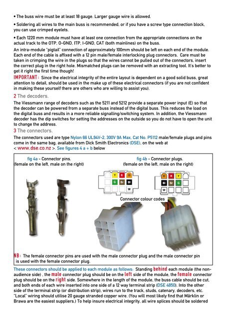
<strong>The</strong> connectors used are type Nylon 66 UL94V-2, 300V 9A Max, Cat No. P5112 male/female plugs and pins<br />
come in the same bag, available from Dick Smith Electronics (DSE), on the web at<br />
< www.dse.co.nz >. See figures 4 a + b below<br />
fig 4a - Connector pins. fig 4b - Connector plugs.<br />
(female on the left, male on the right) (female on the left, male on the right)<br />
Connector colour codes<br />
NB: <strong>The</strong> female connector pins are used with the male connector plug and the male connector pin<br />
is used with the female connector plug.<br />
<strong>The</strong>se connectors should be applied to each module as follows: Standing behind each module (the nonaudience<br />
side) , the male connector plug should be on the left side of the module, the female connector<br />
plug should be on the right side. Somewhere in the length of the module, the buss cable should be cut,<br />
and both ends of each wire inserted into one side of a 12 way terminal strip (DSE 4850). Into the other<br />
side of the terminal strip (or distribution strip), wires run to the track, studs, catenary, decoders, etc.<br />
“Local” wiring should utilise 20 gauge stranded copper wire. (You will most likely find that <strong>Märklin</strong> or<br />
Brawa are the easiest suppliers.) To help insure electrical integrity, all wire splices should be soldered<br />
G<br />
R