The Auckland Märklin Club Inc - The Auckland Marklin Club Inc
The Auckland Märklin Club Inc - The Auckland Marklin Club Inc
The Auckland Märklin Club Inc - The Auckland Marklin Club Inc

You also want an ePaper? Increase the reach of your titles
YUMPU automatically turns print PDFs into web optimized ePapers that Google loves.
• <strong>The</strong> catenary will be connected to the main wiring buss (it may or may not be used in the future) but<br />
please ensure there is electrical continuity across your module.<br />
• NB: <strong>The</strong> <strong>Märklin</strong> catenary is fully functional without modification.<br />
• In all likely hood any analogue E Loks should have their sliders removed (as recommended by <strong>Märklin</strong>)<br />
to use the Catenary as it will have non-digital operating characteristics.<br />
Wiring.<br />
A separate electrical buss system is probably not absolutely needed when using <strong>Märklin</strong> “C” track. In<br />
the <strong>Märklin</strong> Insider Digital Book, it says that larger layouts require a separate buss so our system uses a<br />
separate buss system this to improve reliability and to facilitate unique wiring requirements. <strong>The</strong> wiring<br />
system is designed to accommodate only AC 3-Rail, <strong>Märklin</strong> (Motorola) Digital and also be compatible<br />
with “<strong>Märklin</strong> Systems” controllers (not the Mobile Station unless connected via a CS) We will also have<br />
the ability to run part of the layout in “analogue” mode. Each module or “supermodule” must have one<br />
connection point for the “Control Desk” (located at the rear or “operator”side, extending 300mm from<br />
the rear of the module and wired the same as the interconnection male plug), this gives us the ability<br />
to locate the “Control Desk” almost anywhere within the operational area. We will be using Viessmann<br />
Decoders as they can be supplied by a separate transformer and have no need to be “Boostered” as<br />
the <strong>Märklin</strong> K83/84’s do (less cost, more reliability). At the “Control Desk” the Earth wires will be joined<br />
except when In “Analogue” mode where a switch will break that line.<br />
1 <strong>The</strong> Buss.<br />
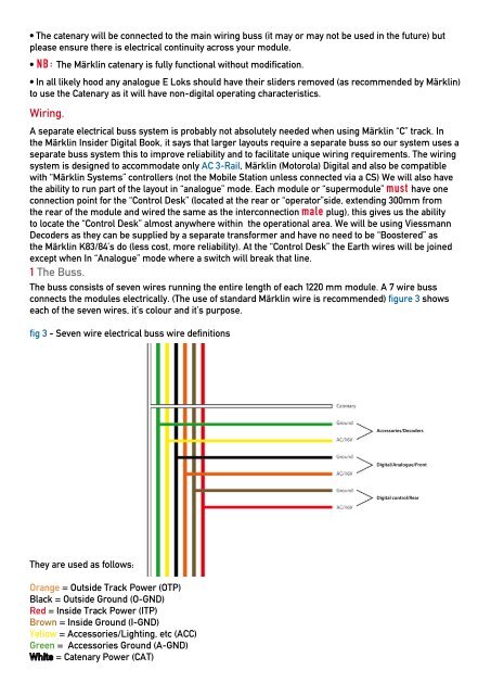
<strong>The</strong> buss consists of seven wires running the entire length of each 1220 mm module. A 7 wire buss<br />
connects the modules electrically. (<strong>The</strong> use of standard <strong>Märklin</strong> wire is recommended) figure 3 shows<br />
each of the seven wires, it’s colour and it’s purpose.<br />
fig 3 - Seven wire electrical buss wire definitions<br />
<strong>The</strong>y are used as follows:<br />
Orange = Outside Track Power (OTP)<br />
Black = Outside Ground (O-GND)<br />
Red = Inside Track Power (ITP)<br />
Brown = Inside Ground (I-GND)<br />
Yellow = Accessories/Lighting, etc (ACC)<br />
Green = Accessories Ground (A-GND)<br />
= Catenary Power (CAT)<br />
Accessories/Decoders<br />
Digital/Analogue/Front<br />
Digital control/Rear