air cooled liquid chillers air cooled liquid chillers
air cooled liquid chillers air cooled liquid chillers
air cooled liquid chillers air cooled liquid chillers

Create successful ePaper yourself
Turn your PDF publications into a flip-book with our unique Google optimized e-Paper software.
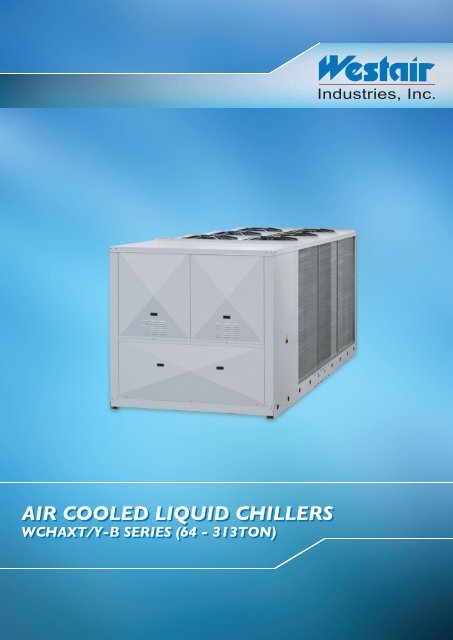
AIR COOLED LIQUID CHILLERS<br />
WCHAXT/Y-B SERIES (64 - 313TON)
INDEX<br />
Pag.<br />
General description <br />
<br />
Versions<br />
<br />
<br />
Technical features<br />
<br />
Factory fitted accessories<br />
<br />
Loose accessories <br />
Reference conditions <br />
Operating range <br />
<br />
Technical data<br />
<br />
Cooling capacity <br />
Heating capacity <br />
<br />
Water circuit pressure drops<br />
<br />
Evaporator water flow limits<br />
<br />
Correction factors<br />
<br />
<br />
Evaporator fouling factors<br />
<br />
corrections<br />
Refrigeration circuit diagram:<br />
Only cooling units<br />
<br />
Heat pump units<br />
<br />
Units with pump:<br />
Technical data<br />
<br />
Characteristic pump curves<br />
<br />
Dimensions and clearances <br />
Position of water connections <br />
<br />
Water circuit:<br />
General characteristics<br />
<br />
Water circuit diagram<br />
<br />
<br />
Weights<br />
<br />
Sound pressure level <br />
Microprocessor control system <br />
<br />
Wiring diagrams<br />
explanation <br />
<br />
Wiring diagrams<br />
<br />
Installation recommendations
GENERAL DESCRIPTION<br />
Air <strong>cooled</strong> water chiller units, with axial fans for outdoor installation.<br />
The range consists of 10 models covering a cooling capacity from 225<br />
to 1102 kW (to 64 TON to 313 TON).<br />
The units feature two independent circuits on both refrigerant and <strong>air</strong><br />
side, allowing to perform maintenance activities in total safety without<br />
stopping the unit.<br />
VERSIONS:<br />
WCHAXT/Y<br />
WCHAXT/Y/WP<br />
- cooling only<br />
- reversible heat pump<br />
TECHNICAL FEATURES:<br />
Frame. Self-supporting galvanized steel frame further protected with<br />
polyester powder painting. Easy to remove panels allow access to the<br />
inside of the unit for maintenance and other necessary operations.<br />
Compressors. Screw semihermetic with built-in oil separator, suction<br />
filter, cranckcase heater, oil sight glass, thermal protection and hot gas<br />
shut off valves.<br />
Fans. Axial fans directly coupled to a three-phase electric motor with<br />
external rotor. A safety fan guard is fitted on the <strong>air</strong> flow discharge.<br />
Condenser.<br />
Two copper tube and aluminum finned coils.<br />
Evaporator. r.<br />
Shell and tube, with two indipendent refrigerant circuits<br />
and one water circuit.<br />
Electrical board. Includes: main switch with door safety interlock; fuses,<br />
overloadprotectionforcompressorsandthermocontactsforfans;interface<br />
relays and electrical terminals for external connections.<br />
Microprocessor for automatic control of the unit allowing continuous<br />
display of the operational status of the unit, control set and real water<br />
temperature and, in case of partial or total block of the unit, indication of<br />
security device that intervened.<br />
Electronic proportional device to decrease the sound level, with a<br />
continuous regulation of the fan speed. This device allows also the cooling<br />
functioning of the unit by external temperature till 0°C.<br />
Refrigerant circuit versions WCHAXT/Y.<br />
Each unit includes two independent refrigerant circuits. Produced in<br />
copper tubing, all models have the following components: electronic<br />
expansion valve, economizer (except 1202-B and 2002-B models),<br />
filter-drier, level and humidity indicator, pressure transducer, high and<br />
low pressure switches (with fixed setting) and safety valve.<br />
FACTO<br />
RY FITTED ACCESSORIES:<br />
IM - Magnetothermic switches instead of fuses and thermal relays.<br />
RZ - Stepless regulation of the compressors to adjust the cooling<br />
capacity to the termic load of the system.<br />
CC - Pressostatic condensation control obtained by means of<br />
continuous adjustment of the fan rotation speed.<br />
BT - Low te<br />
mpera<br />
ture<br />
ki<br />
t,<br />
required in case the unit will work with<br />
evaporatorʼs outlet water temperature below 5°C.<br />
HR - Desuperheater with 20% heat recovery.<br />
HRT/S - Total heat recovery serial connected for from 70% to 95%<br />
heat recovery, according to the working conditions.<br />
HR<br />
T/P - Desuperheater with 100% heat recovery.<br />
TX - Epoxy treated condensing coil fins.<br />
PU - Circulating pump inserted inside the unit.<br />
PD - Double circulating pump installed in the unit, working one in<br />
stand-by to the other; by every start request, the pump with the least<br />
number of working hours is activated first.<br />
RF - Cooling circuit shut off valves on <strong>liquid</strong>.<br />
FE<br />
- Evaporator heater with thermostatic control.<br />
SS - Soft start to reduce compressor starting current.<br />
WM - Web<br />
Monitoring: monitoring enables remote management of<br />
the system through communication protocols, GPRS/GSM/TCP-IP.<br />
Authorized users have access to a dashboard display that provides<br />
critical system information from which the user can measure, manage<br />
and report as necessary.<br />
CP - Potential free contacts for remote alarm and control.<br />
LOOSE ACCESSORIES:<br />
MN- High and low pressure gauges for every refrigeration circuit.<br />
CR - Remotecontrolpaneltobe inserted in theroom forremote control<br />
of the unit, with the same functions as that inserted in the machine.<br />
IS - RS 485 serial interface for connection to controls and centralized<br />
supervision systems.<br />
RP - Coil protection guards in steel with cataphoresis treatment and<br />
painting.<br />
AG - Rubber vibration dampers to be inserted at the bottom of the<br />
unit to dampen possible vibrations due to the type of floor where the<br />
machine is installed.<br />
AM - Spring shock absorbers to be inserted at the bottom of the<br />
unit to dampen possible vibrations due to the type of floor where the<br />
machine is installed.<br />
FL - Flow switch<br />
is installed.<br />
to prevnt any water flow interruption.<br />
Refrigerant circuit versions WCHAXT/Y/WP.<br />
The unit in heat pump version, in addition to the components of the only<br />
cooling unit, includes for each circuit: 4-ways reverse valve, <strong>liquid</strong> separaa-<br />
tor on the suction line, <strong>liquid</strong> receiver, check valves, pressure valve on<br />
compressor supply and <strong>liquid</strong> line shut-off valve.<br />
Water circuit.<br />
Includes: evaporator, temperature sensor, antifreeze sensor and water<br />
drain.
REFERENCE CONDITIONS<br />
All technical data, indicated on pages 5 e 6, refer to the following unit<br />
operating conditions:<br />
- cooling:<br />
• entering water temperature 12°C<br />
• leaving water temperature 7°C<br />
• ambient <strong>air</strong> on condenser 46°C.<br />
- heating:<br />
• entering water temperature 40°C<br />
• leaving water temperature 45°C<br />
• ambient inlet <strong>air</strong> 7°C d.b., 6°C w.b.<br />
- sound pressure level (DIN 45635):<br />
measured in the free field conditions at 1m from the unit and at 1,5m<br />
from the ground. According to DIN 45635.<br />
- sound pressure level (ISO 3744):<br />
measured in free field conditions at 1m. As defined by ISO 3744.<br />
The power supply is 400V/<br />
3Ph/50Hz; auxiliary supply is 230V/<br />
1Ph/<br />
50Hz.<br />
OPERA<br />
TING RANGE<br />
Inlet water temperature<br />
Outlet water temperature<br />
Water thermal difference (1)<br />
Ambient <strong>air</strong> temperature<br />
Minimun chilled water outlet<br />
temperature with glycol mixture<br />
Max. operating pressure heat<br />
exchanger water side<br />
<br />
Cooling<br />
<br />
Heating<br />
<br />
°C 8 20 25 45<br />
°C 5* 15 30 50<br />
°C 3 9 3 10<br />
°C 0** 52 -5 20<br />
°C -8* -----<br />
kPa<br />
ft WG<br />
1000<br />
333<br />
* Low temperature kit, required in case the unit will work with<br />
evaporatorʼs outlet water temperature below 5°C.<br />
** This value can be reduced until -20°C with an optional accessory<br />
supplied prefabricated (CC).<br />
(1) In all cases the water range will have to re-enter within the reported<br />
limits on pag. 9.
TECHNICAL DAT<br />
ATA<br />
A<br />
MODEL<br />
Cooling:<br />
Cooling Capacity (1)<br />
Absorbed power (1)<br />
Cooling Capacity (2)<br />
Absorbed power (2)<br />
Heating:<br />
Heating capacity (1)<br />
Absorbed power (1)<br />
Compressors:<br />
Quantity<br />
Refrigerant Circuits<br />
Capacity steps<br />
Evaporator:<br />
Pressure drops (1)<br />
Pressure drops (2)<br />
Water connections<br />
Water volume<br />
Compressor:<br />
Unitary absorbed power (1)<br />
Unitary absorbed current (1)<br />
Unitary absorbed power (2)<br />
Unitary absorbed current (2)<br />
Oil charge<br />
Standard version:<br />
Fans<br />
Nominal power - fans<br />
Nominal current - fans<br />
Sound pressure level DIN (1)<br />
Sound pressure level ISO (1)<br />
Refrigerant charge R134a<br />
cooling only<br />
Refrigerant charge R134a<br />
heat pump<br />
Lenght<br />
Width<br />
Height<br />
Transport weight cooling only<br />
Transport weight heat pump units<br />
Total electrical consumption:<br />
Power supply<br />
Max. Current<br />
Starting current<br />
<br />
kW 193 237 286 339 391<br />
TON 54,9 67,4 81,3 96,4 111<br />
kW 100 112 134 161 179<br />
kW 225 275 329 390 453<br />
TON 64,0 78,2 93,5 111 129<br />
kW 85 96 114 137 152<br />
kW 229 268 317 380 448<br />
TON 65,1 76,2 90,1 108 127<br />
kW 79 84 93 106 117<br />
n° 2 2 2 2 2<br />
n° 2 2 2 2 2<br />
n° 6 6 6 6 6<br />
l/s 9,22 11,32 13,66 16,20 18,68<br />
gpm 146,1 179,4 216,5 256,8 296,1<br />
kPa 41 38 49 50 53<br />
ft WG 13,7 12,7 16,3 16,7 17,7<br />
l/s 10,75 13,14 15,72 18,63 21,64<br />
gpm 170,4 208,3 249,2 295,3 343,0<br />
kPa 56 51 65 66 71<br />
ft WG 18,6 17,1 21,6 22,1 23,8<br />
DN 100 125 125 125 125<br />
l 35 35 35 35 35<br />
gal 9,2 9,2 9,2 9,2 9,2<br />
kW 46,0 52,0 63,0 74,5 83,5<br />
A 72 72 88 97 111<br />
kW 38,6 43,8 51,0 62,5 70,0<br />
A 62 62 77 82 100<br />
Kg 10 10 10 10 10<br />
m³/s 20,6 23,8 31,2 31,2 33,4<br />
cfm 43631 50409 66082 66082 70741<br />
n° 4 4 6 6 6<br />
kW 8,0 8,0 12,0 12,0 12,0<br />
A 17 17 17 26 26<br />
dB(A) 79 80 80 80 81<br />
dB(A) 68 68 68 68 68<br />
Kg 42 52 56 64 84<br />
Kg 44 55 59 67 88<br />
mm 2800 2800 4000 4000 5000<br />
mm 2200 2200 2200 2200 2200<br />
mm 2500 2500 2500 2500 2500<br />
kg 2670 2800 3150 3300 3740<br />
kg 3110 3250 3610 3780 4340<br />
V/Ph/Hz <br />
A 169 169 203 230 260<br />
A 244 244 261 320 335<br />
(1) Referential conditions at page 4.<br />
(2) Chilled water from 12 to 7°C, <strong>air</strong> condenser 35 °C
TECHNICAL DAT<br />
ATA<br />
A<br />
MODEL<br />
Cooling:<br />
Cooling Capacity (1)<br />
Absorbed power (1)<br />
Cooling Capacity (2)<br />
Absorbed power (2)<br />
Heating:<br />
Heating capacity (1)<br />
Absorbed power (1)<br />
Compressors:<br />
Quantity<br />
Refrigerant Circuits<br />
Capacity steps<br />
Evaporator:<br />
Pressure drops (1)<br />
Pressure drops (2)<br />
Water connections<br />
Water volume<br />
Compressor:<br />
Unitary absorbed power (1)<br />
Unitary absorbed current (1)<br />
Unitary absorbed power (2)<br />
Unitary absorbed current (2)<br />
Oil charge<br />
Standard version:<br />
Fans<br />
Nominal power - fans<br />
Nominal current - fans<br />
Sound pressure level DIN (1)<br />
Sound pressure level ISO (1)<br />
Refrigerant charge R134a<br />
cooling only<br />
Refrigerant charge R134a<br />
heat pump<br />
Lenght<br />
Width<br />
Height<br />
Transport weight cooling only<br />
Transport weight heat pump units<br />
Total electrical consumption:<br />
Power supply<br />
Max. Current<br />
Starting current<br />
kW<br />
TON<br />
kW<br />
kW<br />
TON<br />
kW<br />
kW<br />
TON<br />
kW<br />
n°<br />
n°<br />
n°<br />
l/s<br />
gpm<br />
kPa<br />
ft WG<br />
l/s<br />
gpm<br />
kPa<br />
ft WG<br />
DN<br />
l<br />
gal<br />
kW<br />
A<br />
kW<br />
A<br />
Kg<br />
m³/s<br />
cfm<br />
n°<br />
kW<br />
A<br />
dB(A)<br />
dB(A)<br />
Kg<br />
Kg<br />
mm<br />
mm<br />
mm<br />
kg<br />
kg<br />
V/Ph/Hz<br />
A<br />
A<br />
<br />
452 540 671 797 952<br />
129 154 191 227 271<br />
206 249 306 366 431<br />
517 618 765 910 1092<br />
147 176 217 259 310<br />
175 210 260 304 358<br />
529 610 756 883 982<br />
150 173 215 251 279<br />
141 167 209 243 281<br />
2 2 2 2 2<br />
2 2 2 2 2<br />
6 6 6 6 6<br />
21,60 25,80 32,06 38,08 45,48<br />
342,4 408,9 508,2 603,6 720,9<br />
43 56 64 65 58<br />
14,3 18,7 21,3 21,7 19,3<br />
24,7 29,5 36,5 43,4 52,1<br />
391,5 468,1 579,3 689,2 826,9<br />
56 73 83 91 91<br />
18,7 24,5 27,7 30,4 30,3<br />
150 150 150 150 150<br />
80 80 80 80 80<br />
21,1 21,1 21,1 21,1 21,1<br />
97,0 114,5 143,0 172,0 203,0<br />
136 163 203 233 248<br />
79,5 97,0 119,0 139,5 166,5<br />
119 141 180 195 219<br />
18 18 20 20 20<br />
40,5 46,6 58,3 70,0 76,3<br />
85779 98699 123480 148260 161604<br />
8 8 12 14 14<br />
16,0 16,0 22,0 25,0 25,0<br />
40 40 48 56 56<br />
81 82 83 84 84<br />
69 70 70 70 70<br />
84 106 120 210 240<br />
88 111 126 221 252<br />
5000 5000 7200 8400 8400<br />
2200 2200 2200 2200 2200<br />
2500 2500 2500 2500 2500<br />
4150 4300 5600 6530 7100<br />
4890 4950 6370 7270 7910<br />
<br />
312 386 470 537 578<br />
454 497 618 773 908<br />
(1) Referential conditions at page 4.<br />
(2) Chilled water from 12 to 7°C, <strong>air</strong> condenser 35 °C
COOLING CAPACITY<br />
<br />
<br />
<br />
<br />
<br />
<br />
<br />
<br />
<br />
<br />
<br />
To<br />
(°C)<br />
AMBIENT AIR TEMPERA<br />
TURE °C<br />
30 40 49 52<br />
kWf TONf kWe<br />
kWf TONf kWe<br />
kWf TONf kWe<br />
kWf TONf kWe<br />
kWf TONf kWe<br />
kWf TONf kWe<br />
5 224 63,7 77,1 211 60,0 83,2 197 56,0 89,7 179 50,9 98,3 171 48,6 103 161 45,8 107<br />
6 231 65,7 78,1 218 62,0 84,2 203 57,7 90,8 186 52,9 99,1 175 49,8 104 168 47,8 108<br />
238 67,7 79,2 211 60,0 91,8 183 52,0 104 174 49,5 109<br />
8 246 69,9 80,3 232 66,0 86,3 217 61,7 92,7 199 56,6 101 190 54,0 105 181 51,5 109<br />
9 254 72,2 81,4 239 68,0 87,5 225 64,0 93,5 206 58,6 101 197 56,0 106 187 53,2 110<br />
10 262 74,5 82,5 247 70,2 88,3 233 66,3 94,5 213 60,6 102 204 58,0 106 194 55,2 110<br />
5 272 77,3 86,3 256 72,8 93,2 241 68,5 101 221 62,8 110 210 59,7 115 199 56,6 120<br />
6 281 79,9 87,3 266 75,6 94,1 249 70,8 102 229 65,1 111 218 62,0 116 207 58,9 121<br />
290 82,5 88,9 258 73,4 103 226 64,3 117 196 55,7 106<br />
8 300 85,3 89,9 283 80,5 98,1 267 75,9 104 246 69,9 113 234 66,5 118 203 57,7 107<br />
9 309 87,9 91,5 293 83,3 98,1 275 78,2 105 254 72,2 114 243 69,1 118 211 60,0 108<br />
10 319 90,7 92,5 302 85,9 99,2 286 81,3 106 263 74,8 115 251 71,4 119 219 62,3 108<br />
5 325 92,4 103 301 85,6 111 289 82,2 120 266 75,6 131 254 72,2 138 218 62,0 126<br />
6 336 95,5 105 318 90,4 113 300 85,3 122 276 78,5 133 263 74,8 139 227 64,5 127<br />
347 98,7 106 310 88,1 123 274 77,9 139 237 67,4 127<br />
8 359 102 107 340 96,7 115 322 91,6 124 288 81,9 134 283 80,5 141 219 62,3 112<br />
9 371 106 109 352 100 117 332 94,4 126 306 87,0 136 293 83,3 142 227 64,5 113<br />
10 383 109 110 362 103 118 344 97,8 127 317 90,1 137 304 86,4 143 236 67,1 113<br />
5 386 110 124 366 104 134 343 97,5 144 316 89,9 158 301 85,6 165 286 81,3 172<br />
6 400 114 126 377 107 136 356 101 146 327 93,0 159 312 88,7 167 297 84,5 174<br />
412 117 128 369 105 148 324 92,1 168 307 87,3 175<br />
8 425 121 129 404 115 139 380 108 150 351 99,8 162 336 95,5 170 320 91,0 176<br />
9 440 125 131 417 119 141 394 112 151 364 104 164 348 99,0 170 331 94,1 177<br />
10 455 129 133 430 122 142 406 115 153 376 107 165 360 102 172 344 97,8 178<br />
5 445 127 137 422 120 148 397 113 160 364 104 175 348 99,0 183 299 85,0 168<br />
6 460 131 139 436 124 150 410 117 162 378 108 177 361 103 185 312 88,7 169<br />
476 135 141 425 121 164 375 107 187 323 91,8 171<br />
8 491 140 143 467 133 154 440 125 166 406 115 180 389 111 188 301 85,6 149<br />
9 508 144 144 483 137 156 456 130 168 420 119 182 403 115 190 312 88,7 151<br />
10 524 149 146 497 141 158 469 133 170 435 124 184 417 119 192 323 91,8 152<br />
5 508 144 158 483 137 171 455 129 185 419 119 203 400 114 212 381 108 222<br />
6 527 150 160 499 142 173 470 134 187 434 123 205 415 118 214 396 113 224<br />
545 155 163 488 139 189 431 123 215 412 117 225<br />
8 561 160 165 535 152 177 505 144 191 467 133 208 448 127 217 428 122 226<br />
9 581 165 166 553 157 179 522 148 193 485 138 210 464 132 219 445 127 227<br />
10 600 171 169 571 162 181 542 154 195 502 143 211 482 137 220 414 118 201<br />
5 607 173 189 577 164 205 542 154 223 503 143 244 481 137 256 458 130 269<br />
6 627 178 193 597 170 208 564 160 225 521 148 247 500 142 258 427 121 237<br />
651 185 195 585 166 227 520 148 260 443 126 239<br />
8 673 191 198 639 182 213 605 172 230 561 160 251 536 152 263 460 131 241<br />
9 695 198 200 663 189 216 628 179 232 580 165 254 558 159 264 479 136 242<br />
10 716 204 203 681 194 218 648 184 235 601 171 255 579 165 266 439 125 212<br />
5 750 213 234 714 203 253 674 192 274 622 177 301 598 170 314 570 162 329<br />
6 778 221 237 738 210 256 700 199 277 647 184 303 620 176 317 592 168 331<br />
807 230 240 724 206 280 642 183 320 614 175 334<br />
8 834 237 243 792 225 263 749 213 283 698 199 309 667 190 323 641 182 336<br />
9 860 245 247 818 233 266 776 221 286 720 205 312 694 197 325 664 189 339<br />
10 889 253 250 846 241 270 804 229 289 747 212 315 716 204 328 688 196 341<br />
5 893 254 271 853 243 295 800 228 325 742 211 359 708 201 378 675 192 397<br />
6 928 264 274 885 252 296 832 237 328 768 218 362 736 209 380 702 200 400<br />
960 273 277 861 245 330 763 217 383 732 208 401<br />
8 987 281 279 941 268 306 890 253 334 827 235 368 793 226 387 679 193 356<br />
9 1020 290 282 971 276 309 921 262 337 857 244 371 823 234 390 704 200 357<br />
10 1054 300 285 1003 285 312 953 271 340 886 252 375 853 243 392 731 208 360<br />
5 1074 305 320 1018 290 351 959 273 383 884 251 424 843 240 446 803 228 469<br />
6 1114 317 324 1055 300 354 993 282 386 915 260 428 874 249 450 835 237 472<br />
1146 326 327 1025 292 391 907 258 453 867 247 473<br />
8 1190 338 330 1130 321 361 1062 302 394 987 281 434 945 269 455 808 230 418<br />
9 1231 350 334 1168 332 364 1103 314 398 1021 290 438 978 278 460 837 238 421<br />
10 1272 362 338 1208 344 368 1138 324 401 1055 300 443 1011 288 464 869 247 425<br />
kWf: Cooling capacity (kW).<br />
TONf: Cooling capacity (TON).<br />
kWe: Power input (kW).<br />
To: Evaporator leaving water temperature ( in./out =5 K).
HEA<br />
TING CAPACITY<br />
ACITY<br />
<br />
Ta (°C)<br />
RH(%)<br />
CONDENSER INLET/OUTLET WA<br />
TER TEMPERA<br />
TURE °C<br />
30/35 35/40 <br />
kWt TONt kWe<br />
kWt TONt kWe<br />
kWt TONt kWe<br />
<br />
<br />
<br />
<br />
<br />
<br />
<br />
<br />
<br />
<br />
0 90 186 52,9 64,4 188 53,5 70,0 190 54,0 76,0<br />
5 90 211 60,0 65,1 214 60,8 72,2 216 61,4 78,2<br />
223 63,4 65,6 226 64,3 72,2 <br />
10 70 232 66,0 66,0 234 66,5 73,3 236 67,1 80,0<br />
15 60 252 71,7 66,7 253 71,9 73,5 254 72,2 80,0<br />
0 90 218 62,0 68,8 220 62,6 75,1 223 63,4 81,0<br />
5 90 247 70,2 69,2 250 71,1 75,9 252 71,7 83,2<br />
261 74,2 69,2 265 75,4 77,1 <br />
10 70 271 77,1 70,2 274 77,9 77,1 276 78,5 85,0<br />
15 60 295 83,9 70,6 296 84,2 78,0 297 84,5 86,1<br />
0 90 258 73,4 74,0 260 73,9 82,0 263 74,8 89,2<br />
5 90 292 83,0 75,2 295 83,9 84,2 299 85,0 92,1<br />
308 87,6 77,1 313 89,0 84,3 <br />
10 70 320 91,0 77,1 324 92,1 84,7 327 93,0 93,3<br />
15 60 349 99,2 78,2 351 99,8 86,0 352 100 94,4<br />
0 90 308 87,6 85,4 313 89,0 94,2 316 89,9 102<br />
5 90 350 99,5 87,1 354 101 96,0 359 102 105<br />
370 105 88,3 376 107 96,0 <br />
10 70 384 109 88,3 388 110 97,1 392 112 107<br />
15 60 418 119 89,1 420 119 98,2 422 120 108<br />
0 90 364 104 94,2 368 105 103 372 106 113<br />
5 90 412 117 95,2 417 119 105 423 120 116<br />
437 124 96,4 442 126 106 <br />
10 70 454 129 97,5 458 130 107 462 131 118<br />
15 60 494 141 98,1 495 141 108 497 141 119<br />
0 90 429 122 113 434 123 126 440 125 136<br />
5 90 486 138 115 493 140 128 499 142 139<br />
515 146 116 522 148 129 <br />
10 70 535 152 118 541 154 129 546 155 142<br />
15 60 583 166 119 585 166 131 587 167 143<br />
0 90 495 141 134 501 143 148 506 144 162<br />
5 90 561 160 137 568 162 150 575 164 165<br />
594 169 138 602 171 151 <br />
10 70 617 175 139 624 177 152 629 179 168<br />
15 60 673 191 141 675 192 154 677 193 170<br />
0 90 614 175 167 621 177 185 628 179 201<br />
5 90 695 198 171 705 201 188 713 203 207<br />
737 210 172 746 212 189 <br />
10 70 765 218 173 773 220 190 780 222 211<br />
15 60 834 237 175 836 238 194 839 239 212<br />
0 90 717 204 194 725 206 215 733 208 234<br />
5 90 813 231 199 822 234 219 832 237 240<br />
860 245 200 871 248 221 <br />
10 70 893 254 202 903 257 222 912 259 245<br />
15 60 973 277 204 976 278 225 980 279 247<br />
0 90 797 227 226 806 229 249 816 232 271<br />
5 90 903 257 229 915 260 253 927 264 278<br />
957 272 232 969 276 255 <br />
10 70 994 283 233 1004 286 257 1013 288 283<br />
15 60 1083 308 237 1086 309 260 1091 310 285<br />
Ta: Ambient <strong>air</strong> temperature dry bulb (°C)<br />
RH: Ambient <strong>air</strong> relative humidity (%)<br />
kWt: Heating capacity (kW)<br />
TONt: Heating capacity (TON).<br />
kWe: Power input (kW)
WA<br />
TER CIRCUIT PRESSURE DROPS<br />
ft WG<br />
66,6<br />
kPa<br />
200<br />
P erdite di carico - Pressure drop s<br />
33,3<br />
30,0<br />
26,6<br />
23,3<br />
20,0<br />
16,6<br />
13,3<br />
10,0<br />
100<br />
90<br />
80<br />
70<br />
60<br />
50<br />
40<br />
30<br />
1202-B<br />
1302-B<br />
1502-B<br />
1702-B<br />
1902-B<br />
2002-B<br />
2602-B<br />
3002-B<br />
3602-B<br />
4202-B<br />
6,6<br />
20<br />
3,3<br />
10<br />
3 4<br />
6 8 10 15 20 30 40 50 70 l/s<br />
47,5 63,4<br />
95,1 126,8 158,5 237,7 317,0<br />
475,5 634,0 792,5 1109,5 gpm<br />
Water flow<br />
EVAPOR<br />
APORA<br />
ATORS WA<br />
TER FLOW LIMITS<br />
Model<br />
<br />
l/s 4,6 5,7 7,1 7,1 8,4 9,2 10,5 12,9 14,1 19,4<br />
gpm 72,9 90,4 112,5 112,5 133,1 145,8 166,4 204,5 223,5 307,5<br />
l/s 13,3 18,2 20,6 20,6 24,7 28,5 32,9 39,8 47,4 59,5<br />
gpm 210,8 288,5 326,5 326,5 391,5 451,7 521,5 630,8 751,3 943,1<br />
CORRECTION FACTORS<br />
If an unit is made to operate with a glycol-water solution, the following correction factors should be applied to any calculations.<br />
Ethylene glycol percent by<br />
weight (%)<br />
Freezing point ( °C)<br />
Cooling capacity corr. factor<br />
Power input corr. factor<br />
Pressure drop corr. factor<br />
<br />
0 -4,5 -9,5 -15,5 -21,5 -32,5<br />
1 0,975 0,95 0,93 0,91 0,88<br />
1 1,01 0,995 0,990 0,985 0,975<br />
1 1,01 1,04 1,08 1,14 1,20<br />
1 1,05 1,13 1,21 1,26 1,32<br />
Evaporator fouling factor corrections<br />
0 Clean evaporator<br />
0,44 x 10 -4 (m² °C/W)<br />
0,88 x 10 -4 (m² °C/W)<br />
1,76 x 10 -4 (m² °C/W)<br />
f1: capacity correction factors;<br />
fp1: compressor power input correction factor;<br />
unit performances reported in the tables are given for the condition<br />
of clean exchanger (fouling factor = 0). For different fouling<br />
factors values, unit performances should be corrected with the<br />
correction factors shown above.<br />
<br />
<br />
<br />
1 1<br />
0,98 0,99<br />
0,96 0,99<br />
0,93 0,98
REFRIGERA<br />
TION CIRCUIT DIAGRAM<br />
WCHAXT/Y 1202-B and 2002-B<br />
Only cooling units<br />
VDS<br />
VDS<br />
RM<br />
CA<br />
MV<br />
RM<br />
MHP<br />
TP<br />
MHP<br />
TP<br />
SPH<br />
SPS<br />
P><br />
P><br />
VP<br />
RC<br />
FD<br />
RLL<br />
RLL<br />
FD<br />
SPH<br />
SPS<br />
P><br />
P><br />
RC<br />
VP<br />
SPL<br />
P<<br />
MLP<br />
MC<br />
TP<br />
SF<br />
VT<br />
T<br />
VT<br />
SF<br />
SPL<br />
P<<br />
MLP<br />
MC<br />
TP<br />
EW<br />
VDS<br />
TP<br />
T<br />
T<br />
T<br />
T<br />
TP<br />
VDS<br />
<br />
<br />
<br />
<br />
<br />
<br />
<br />
<br />
<br />
<br />
<br />
<br />
<br />
<br />
<br />
<br />
<br />
<br />
DESIGNA<br />
TION<br />
Condenser<br />
Evaporator<br />
Filter-drier<br />
Compressor<br />
High pressure guage<br />
(accessory<br />
)<br />
Low pressure guage<br />
(accessory<br />
)<br />
Axial fans<br />
Crank case heater<br />
Liquid line shut-off valve<br />
(accessory<br />
)<br />
Discharge line<br />
Sight glass<br />
High pressure switch<br />
Low pressure switch<br />
Safety pressure gauges<br />
Pressure transmitter<br />
Safety valve<br />
Step regulation valve<br />
stepless (accessory )<br />
Electronic expansion valve
REFRIGERA<br />
TION CIRCUIT DIAGRAM<br />
WCHAXT/Y 1302-B to1902-B and 2602-B to 4202-B<br />
Only cooling units<br />
VDS<br />
VDS<br />
RM<br />
CA<br />
MV<br />
RM<br />
TP<br />
TP<br />
MHP<br />
SF<br />
FD<br />
RLL<br />
RLL<br />
FD<br />
SF<br />
MHP<br />
SPS<br />
P><br />
SPS<br />
P><br />
SPH<br />
P><br />
VP<br />
RC<br />
SPH<br />
P><br />
RC<br />
VP<br />
SPL<br />
P<<br />
MC<br />
ELE<br />
VTE<br />
SCE<br />
SCE<br />
VTE<br />
ELE<br />
P<<br />
SPL<br />
MC<br />
MLP<br />
TP<br />
VT<br />
VT<br />
MLP<br />
TP<br />
T<br />
EW<br />
VDS<br />
TP<br />
T<br />
T<br />
T<br />
T<br />
TP<br />
VDS<br />
<br />
<br />
<br />
<br />
<br />
<br />
<br />
<br />
<br />
<br />
<br />
<br />
<br />
<br />
<br />
<br />
<br />
<br />
<br />
<br />
<br />
DESIGNA<br />
TION<br />
Condenser<br />
Electro valve (economizer)<br />
Evaporator<br />
Filter-drier<br />
Compressor<br />
High pressure guage<br />
(accessory)<br />
Low pressure guage<br />
(accessory)<br />
Axial fans<br />
Crank case heater<br />
Liquid line shut-off valve<br />
(accessory)<br />
Discharge line<br />
Heat exchanger<br />
(economizer)<br />
Sight glass<br />
High pressure switch<br />
Low pressure switch<br />
Safety pressure gauges<br />
Pressure transmitter<br />
Safety valve<br />
Step regulation valve<br />
stepless (accessory)<br />
Electronic expansion<br />
valve<br />
Thermostatic valve<br />
(economizer)
REFRIGERA<br />
TION CIRCUIT DIAGRAM<br />
WCHAXT/Y/WP 1302-B to1902-B and 2602-B to 6302-B<br />
Heat pump units<br />
CV<br />
CV<br />
CV<br />
CV<br />
VT<br />
SCE<br />
VTE<br />
ELE<br />
ELE<br />
VTE<br />
VT<br />
SCE<br />
FD<br />
FD<br />
CV<br />
SF<br />
RLL<br />
CV<br />
LR<br />
LR<br />
CV<br />
RLL<br />
SF<br />
CV<br />
MV<br />
CEC<br />
VDS<br />
RCV<br />
TP<br />
TP<br />
RCV<br />
VDS<br />
VDS<br />
VP<br />
T<br />
VPR MHP<br />
RM<br />
RC<br />
MC<br />
TP<br />
P><br />
P><br />
SPS<br />
SPH<br />
T T<br />
SCA<br />
T<br />
SPS<br />
SPH<br />
P><br />
P><br />
T<br />
MHPVPR<br />
RM<br />
RC<br />
MC<br />
TP<br />
VP<br />
VDS<br />
TP<br />
SLG<br />
P<<br />
MLP<br />
SPL<br />
SPL<br />
P<<br />
MLP<br />
SLG<br />
TP<br />
<br />
<br />
<br />
<br />
<br />
<br />
<br />
<br />
<br />
<br />
<br />
<br />
<br />
<br />
<br />
<br />
<br />
<br />
<br />
<br />
<br />
<br />
<br />
DESIGNA<br />
TION<br />
Finned coil<br />
Check valve<br />
Filter-drier<br />
Liquid receiver<br />
Compressor<br />
High pressure guage<br />
(accessory)<br />
Low pressure guage<br />
(accessory)<br />
Axial fans<br />
Crank case heater<br />
4-Way valve<br />
Liquid line shut-off valve<br />
Discharge line<br />
Water <strong>cooled</strong> exchanger<br />
Sight glass<br />
Liquid/gas separator<br />
High pressure switch<br />
Low pressure switch<br />
Safety pressure gauges<br />
Pressure transmitter<br />
Safety valve<br />
Step regulation valve<br />
stepless (accessory)<br />
Pressure valve<br />
Electronic expansion valve
REFRIGERA<br />
TION CIRCUIT DIAGRAM<br />
WCHAXT/Y/WP 1202-B and 2002-B<br />
Heat pump units<br />
CV<br />
CV<br />
CV<br />
CV<br />
VT<br />
VT<br />
FD<br />
FD<br />
CV<br />
SF<br />
RLL<br />
CV<br />
LR<br />
LR<br />
CV<br />
RLL<br />
SF<br />
CV<br />
MV<br />
CEC<br />
VDS<br />
RCV<br />
TP<br />
TP<br />
RCV<br />
VDS<br />
VDS<br />
VP<br />
T<br />
VPR MHP<br />
RM<br />
RC<br />
MC<br />
TP<br />
P><br />
P><br />
SPS<br />
SPH<br />
T T<br />
SCA<br />
T<br />
SPS<br />
SPH<br />
P><br />
P><br />
T<br />
MHPVPR<br />
RM<br />
RC<br />
MC<br />
TP<br />
VP<br />
VDS<br />
TP<br />
SLG<br />
P<<br />
MLP<br />
SPL<br />
SPL<br />
P<<br />
MLP<br />
SLG<br />
TP<br />
<br />
<br />
<br />
<br />
<br />
<br />
<br />
<br />
<br />
<br />
<br />
<br />
<br />
<br />
<br />
<br />
<br />
<br />
<br />
<br />
<br />
<br />
<br />
DESIGNA<br />
TION<br />
Finned coil<br />
Check valve<br />
Filter-drier<br />
Liquid receiver<br />
Compressor<br />
High pressure guage<br />
(accessory)<br />
Low pressure guage<br />
(accessory)<br />
Axial fans<br />
Crank case heater<br />
4-Way valve<br />
Liquid line shut-off valve<br />
Discharge line<br />
Water <strong>cooled</strong> exchanger<br />
Sight glass<br />
Liquid/gas separator<br />
High pressure switch<br />
Low pressure switch<br />
Safety pressure gauges<br />
Pressure transmitter<br />
Safety valve<br />
Step regulation valve<br />
stepless (accessory)<br />
Pressure valve<br />
Electronic expansion valve
UNITS WITH PUMP<br />
Technical data<br />
MODELS<br />
Nominal power - pump<br />
Max. working pressure<br />
Head pressure (1)<br />
Expansion vessel volume (2)<br />
MODELS<br />
Nominal power - pump<br />
Max. working pressure<br />
Head pressure (1)<br />
Expansion vessel volume (2)<br />
<br />
kW 3,0 4,0 5,5 5,5 5,5<br />
kPa 600 600 600 600 600<br />
ft WG 200 200 200 200 200<br />
kPa 175 195 225 205 170<br />
ft WG 58,3 65,0 75,0 68,3 56,7<br />
l 35 35 35 35 35<br />
gal 9,2 9,2 9,2 9,2 9,2<br />
<br />
kW 7,5 7,5 7,5 11 11<br />
kPa 600 600 600 600 600<br />
ft WG 200 200 200 200 200<br />
kPa 190 165 125 160 140<br />
ft WG 63,3 55,0 41,7 53,3 46,7<br />
l 80 80 80 80 80<br />
gal 21,1 21,1 21,1 21,1 21,1<br />
Weight<br />
calculation: The weight in operation indicated below is<br />
composed of:<br />
- weight of the pump and pipework.<br />
The value is then to be added to the TRANSPORT WEIGHT of the<br />
machine referred to. The result is the total weight of the unit in opera-<br />
tion. This is a necessary detail to calculate the concrete base of the<br />
chiller and select antivibration mounts.<br />
Additional weight in operation and water connections<br />
MODELS<br />
<br />
Additional weight while funct. Kg 130 150 170 170 170<br />
Water connections<br />
DN 100 100 100 100 125<br />
Additional weight while funct. Kg 215 255 280 280 280<br />
Water connections<br />
DN 100 100 100 100 125<br />
MODELS<br />
<br />
Additional weight while funct. Kg 205 205 205 305 345<br />
Water connections<br />
DN 125 150 150 150 200<br />
Additional weight while funct. Kg 355 355 355 520 585<br />
Water connections<br />
DN 125 150 150 150 200<br />
(1) Referential conditions at page 4.<br />
(2) The expansion vessel on the units with single pump has a content of 24 lt (gal 6,3).
UNITS WITH STORAGE TANK AND PUMPS<br />
Characteristic pump curves<br />
<br />
<br />
ft WG kPa<br />
ft WG kPa<br />
93,3<br />
280<br />
93,3<br />
280<br />
80,0<br />
240<br />
1202-B<br />
80,0<br />
240<br />
1302-B<br />
66,6<br />
200<br />
66,6<br />
200<br />
53,3<br />
160<br />
53,3<br />
160<br />
40,0<br />
120<br />
40,0<br />
120<br />
26,6<br />
80<br />
26,6<br />
80<br />
13,3<br />
40<br />
13,3<br />
40<br />
0 0<br />
0<br />
0<br />
2 4 6 8 10 12 14 16<br />
31,7 63,4 95,1 126,8 158,5 190,2 221,9 253,6<br />
l/s<br />
gpm<br />
0 0<br />
0<br />
0<br />
2 4 6 8 10 12 14 16<br />
31,7 63,4 95,1 126,8 158,5 190,2 221,9 253,6<br />
l/s<br />
gpm<br />
<br />
ft WG kPa<br />
116,6 350<br />
<br />
ft WG kPa<br />
120,0 360<br />
100,0<br />
83,3<br />
66,6<br />
300<br />
250<br />
200<br />
1502-B<br />
1702-B<br />
1902-B<br />
93,3 280<br />
66,6 200<br />
2002-B<br />
2602-B3002-B<br />
50,0<br />
33,3<br />
150<br />
100<br />
40,0 120<br />
16,6<br />
50<br />
13,3<br />
40<br />
0 0<br />
0 5 10 15 20 25 30<br />
0 79,2 158,5 237,7 317,0 396,2 475,5<br />
I/s<br />
gpm<br />
0<br />
0<br />
0 10<br />
20 30<br />
40 I/s<br />
0 158,5 317,0 475,5 634,0 gpm<br />
<br />
ft WG kPa<br />
120,0<br />
360<br />
93,3<br />
280<br />
66,6 200<br />
4202-B<br />
3602-B<br />
40,0 120<br />
13,3<br />
0<br />
40<br />
0<br />
0 10 20 30 40 50 60<br />
0 158,5 317,0 475,5 634,0 792,5 951,0<br />
I/s<br />
gpm
A<br />
Y Y<br />
DIMENSIONS AND CLEARANCES<br />
Only cooling units<br />
X<br />
C<br />
X<br />
B<br />
View "X-X"<br />
1800 mm<br />
Y - Water connections.<br />
500 mm<br />
1000 mm<br />
Clearance area<br />
1800 mm<br />
DIMENSIONS<br />
<br />
A mm 2800 2800 4000 4000 5000 5000 5000 7200 8400 8400<br />
B mm 2200 2200 2200 2200 2200 2200 2200 2200 2200 2200<br />
C mm 2500 2500 2500 2500 2500 2500 2500 2500 2500 2500
POSITION OF WA<br />
TER CONNECTIONS<br />
IN<br />
OUT<br />
D<br />
E<br />
F<br />
STANDARD CONFIGURATION: hydraulic connections on the left side panel view.<br />
On request, attacks on the right side (mirror dimensions).<br />
<br />
D mm 420 450 450 450 450 460 460 400 400 400<br />
E mm 200 200 500 500 1300 900 900 1900 2000 1800<br />
F mm 1830 1750 2150 2150 2150 2500 2500 3100 2900 3500
WA<br />
TER CIRCUIT<br />
General characteristics<br />
Water circuit<br />
t.<br />
Includes:evaporator,temperaturesensor,antifreezesensorandwaterdrain.<br />
PU - Water circuit with additional circulation pump.<br />
Includes: evaporator, temperature sensor, antifreeze sensor, circula-<br />
expansion vessel, safety valve and thermal relay.<br />
PD - Water circuit with additional double circulation pump.<br />
Includes: evaporator, temperature sensor, antifreeze sensor, double<br />
lines, expansion vessel, safety valve, check valve and thermal relais.<br />
WA<br />
TER CIRCUIT DIAGRAM<br />
DESIGNA<br />
TION<br />
<br />
Gate valve<br />
<br />
Evaporator<br />
<br />
Flow switch<br />
<br />
Water manometer<br />
<br />
Double circulating pump<br />
<br />
Single circulating pump<br />
<br />
<br />
<br />
Intercepting valve<br />
Water drain<br />
<br />
Air vent<br />
<br />
<br />
<br />
<br />
<br />
Sensor for unit operation<br />
Antifreeze sensor<br />
Expansion vessel<br />
<br />
<br />
Safety valve (600 kPa - 200 ft WG)
WEIGHTS<br />
X-X<br />
100 200<br />
X<br />
K3<br />
K2<br />
K1<br />
K6<br />
K5<br />
6xØ18<br />
K4<br />
40<br />
X-X<br />
100 200<br />
500<br />
X<br />
900<br />
900<br />
500<br />
2800<br />
40<br />
1200<br />
500<br />
K4 K8<br />
K4 K9<br />
X X X X<br />
900<br />
1000<br />
K3 K7<br />
K3 K8<br />
K2 K6<br />
X-X<br />
100200<br />
4000<br />
100200<br />
40<br />
500<br />
K5 K10<br />
1200 900<br />
K2 K7<br />
8xØ18 900<br />
10xØ18 900<br />
K1 K5<br />
500<br />
K1 K6<br />
500<br />
X-X<br />
5000<br />
X<br />
K7<br />
K6<br />
K5<br />
K4<br />
K3<br />
K2<br />
K1<br />
X-X<br />
100200<br />
40<br />
500<br />
K14<br />
1200<br />
K13<br />
1000<br />
K12<br />
1200<br />
K11<br />
X<br />
1000<br />
K10<br />
900<br />
K9<br />
14xØ18 900<br />
K8<br />
500<br />
7200<br />
X<br />
K8<br />
K7<br />
K6<br />
K5<br />
K4<br />
K3<br />
K2<br />
K1<br />
40<br />
K16 500<br />
1200<br />
X<br />
K15<br />
1000<br />
K14<br />
1200<br />
K13<br />
1000<br />
K12<br />
900<br />
K11<br />
1200<br />
K10<br />
900<br />
K9<br />
500<br />
8400<br />
OPERA<br />
TING WEIGHT (Kg)<br />
<br />
K1 Kg 450 460 410 430 400 440 450 440 470 500<br />
K2 Kg 410 420 380 400 370 410 420 410 430 460<br />
K3 Kg 380 390 330 350 340 370 380 370 400 430<br />
K4 Kg 530 580 290 310 300 340 350 340 370 400<br />
K5 Kg 500 550 530 540 270 310 320 320 350 370<br />
K6 Kg 470 510 490 510 500 550 560 280 320 350<br />
K7 Kg --- --- 450 470 470 520 530 260 300 320<br />
K8 Kg --- --- 410 430 440 480 490 580 280 290<br />
K9 Kg --- --- --- --- 400 450 460 550 590 640<br />
K10 Kg --- --- --- --- 370 420 430 530 560 610<br />
K11 Kg --- --- --- --- --- --- --- 500 520 580<br />
K12 Kg --- --- --- --- --- --- --- 460 490 540<br />
K13 Kg --- --- --- --- --- --- --- 430 470 520<br />
K14 Kg --- --- --- --- --- --- --- 400 450 500<br />
K15 Kg --- --- --- --- --- --- --- --- 420 470<br />
K16 Kg --- --- --- --- --- --- --- --- 390 440<br />
<br />
OPERA<br />
TING WEIGHT (Kg)<br />
<br />
K1 Kg 520 535 470 490 460 510 520 495 520 550<br />
K2 Kg 485 495 435 460 430 485 490 470 475 515<br />
K3 Kg 455 465 390 410 400 445 450 430 445 480<br />
K4 Kg 600 655 345 370 360 415 420 400 415 450<br />
K5 Kg 575 625 590 600 330 385 390 380 400 425<br />
K6 Kg 545 585 545 570 560 620 630 340 365 400<br />
K7 Kg --- --- 510 530 530 595 600 315 345 370<br />
K8 Kg --- --- 465 490 500 555 560 640 325 340<br />
K9 Kg --- --- --- --- 460 525 530 605 640 690<br />
K10 Kg --- --- --- --- 430 495 500 590 605 665<br />
K11 Kg --- --- --- --- --- --- --- 560 565 630<br />
K12 Kg --- --- --- --- --- --- --- 520 535 590<br />
K13 Kg --- --- --- --- --- --- --- 490 515 575<br />
K14 Kg --- --- --- --- --- --- --- 455 500 550<br />
K15 Kg --- --- --- --- --- --- --- --- 465 520<br />
K16 Kg --- --- --- --- --- --- --- --- 435 490
The sound level values indicated in accordance with DIN 45635 in<br />
-<br />
ment is taken at 1m distance from the side of condensing coil and<br />
at a height of 1,5 m with respect to the base of the machine. On the<br />
noise levels that are indicated, a tolerance of +/- 3dB(A) should be<br />
considered (according to DIN 45635). The values refer to a machine<br />
without pump.<br />
MODEL<br />
<br />
<br />
<br />
49,5 50,0 50,5 50,5 51,0 52,0 53,5 54,0 54,0 54,5<br />
61,5 61,5 61,5 62,0 62,5 63,0 67,0 67,5 68,0 68,5<br />
73,0 73,5 73,5 73,5 75,0 75,5 75,5 76,0 77,0 77,0<br />
73,5 74,0 74,0 74,0 75,0 76,0 77,0 78,5 79,0 79,5<br />
72,5 73,5 73,5 73,5 74,0 74,5 75,5 76,0 77,0 77,5<br />
71,0 71,0 71,5 71,5 72,0 72,5 73,5 74,0 75,0 74,5<br />
68,5 69,0 69,0 69,5 70,0 70,0 70,5 72,0 72,5 73,0<br />
51,5 52,0 52,5 52,5 53,0 54,0 55,0 55,5 56,0 56,5<br />
<br />
<br />
MICROPROCESSOR CONTROL SYSTEM<br />
A microprocessor controls all the functions of the unit and allows any<br />
adjustments to be made. The set-points and operating parameters<br />
are set directly into the microprocessor. This type of microprocessor<br />
enables the adjustment of up to four compressors. It has a visual<br />
alarm signal, pushbuttons for the various functions, and offers a<br />
continuous control of the system as well as saving all the data in<br />
case of a cut in the power supply. Through the display, one can input<br />
and have an indication of set values.<br />
Principal functions: indication of entering and leaving water temperature;<br />
-<br />
merical code; control of one or two pumps;<br />
at start-up; prestarting of the fans; hour counter of compressors in<br />
operation; automatic changeover of compressor and pump sequence;<br />
compressors start individually and not together; frost protection;<br />
remote on-off; operation signalling; manual operation; manual reset;<br />
electronic card for connection to management and service systems.<br />
Alarms: high and low pressure and overload on each compressor;<br />
.<br />
Accessories: electronic card for connection to management and<br />
service systems, remote display.
WIRING DIAGRAMS EXPLANA<br />
TION<br />
<br />
DESIGNA<br />
TION<br />
DISPLAY (USER INTERFACE)<br />
REMOTE DISPLAY *<br />
<br />
<br />
<br />
<br />
<br />
<br />
<br />
<br />
<br />
<br />
<br />
<br />
<br />
<br />
<br />
<br />
<br />
<br />
<br />
<br />
<br />
<br />
<br />
<br />
<br />
<br />
<br />
<br />
<br />
<br />
<br />
<br />
<br />
<br />
<br />
<br />
<br />
<br />
ECONOMIZER<br />
AUXILIARY CIRCUIT FUSES<br />
COMPRESSOR FUSES CIRCUIT<br />
PUMP FUSES<br />
STORAGE TANK HEATER FUSE<br />
FAN MOTOR FUSES<br />
LIQUID IJECTION<br />
AUXILIARY CONTACTOR<br />
COMPRESSOR CONTACTOR<br />
PUMP CONTACTOR<br />
STORAGE TANK HEATER CONTACTOR<br />
TIMER SWITCH<br />
FAN MOTOR CONTACTOR<br />
COMPRESSOR<br />
PUMP<br />
FAN MOTOR<br />
COMPRESSOR CAPACITY STEPS<br />
FLOW SWITCH<br />
HP SWITCH CIRCUIT<br />
MOTOR PROTECTION COMPRESSOR<br />
LP SWITCH CIRCUIT<br />
STORAGE TANK/EVAPORATOR HEATER<br />
COMP. CRANKCASE HEATER<br />
EVAPORATOR HEATER<br />
PHASE SEQUENCE RELAY<br />
SPEED GOVERNOR<br />
ELECTRICAL BOARD HEATER<br />
PIPES HEATER<br />
COMPRESSOR OVERLOAD RELAY<br />
PUMP OVERLOAD RELAY<br />
ANTIFREEZE SENSOR<br />
MICROPROCESSOR<br />
BY-PASS VALVE<br />
EXPANSION BOARD<br />
MAIN SWITCH<br />
TEMPERATURE SENSOR<br />
LIQUID LINE VALVE<br />
DISCHARGE LINE SENSOR<br />
SERIAL INTERFACE *<br />
<br />
<br />
<br />
<br />
<br />
<br />
<br />
<br />
<br />
AMBIENT AIR TEMPERATUR SENSOR<br />
AMBIENT AIR TEMPERATUR THERMOSTAT<br />
AUXILIARY TRASFORMER<br />
PRESSURE TRANSDUCER<br />
LOW PRESSURE TRANSMITTER<br />
VT PRESSURE TRANSMITTER<br />
ELECTRICAL BOARD THERMOSTAT<br />
AUXILIARY TRASFORMER<br />
REVERSE CYCLE VALVE CIRCUIT<br />
* Loose accessory
11 14 12<br />
L1<br />
L2<br />
L3<br />
9<br />
R 1<br />
B W G B W G + T M B W G B W G + T M<br />
3<br />
2<br />
1<br />
6<br />
5<br />
4<br />
7<br />
8<br />
POWER ELECTRICAL DIAGRAM:<br />
WCHAXT/Y 1202-B to 4202-B<br />
- Wiring diagram explanation at page 21;<br />
- Dotted lines indicate optional electrical connections<br />
or to carry out during the installation.<br />
FC1<br />
FC2<br />
FV1<br />
X1:<br />
SG<br />
KC1<br />
RTC1<br />
KC2<br />
KC5<br />
KC3<br />
RTC3<br />
KC4<br />
KC6<br />
X1:<br />
L1 L2 L3 PE<br />
U V W IN+ IN-<br />
RG1<br />
L1L2 L3 PE<br />
X1:<br />
10<br />
11<br />
SSC1<br />
X1:<br />
19<br />
18<br />
17<br />
SSC2<br />
400V/50Hz/3Ph/PE<br />
RTC2<br />
L1 L2 L3 PE<br />
U V W IN+ IN-<br />
L1 L2 L3 PE<br />
U V W IN+ IN-<br />
RTC4<br />
Y-<br />
Y+<br />
X1:<br />
12<br />
16<br />
15<br />
14<br />
13<br />
X1:<br />
24<br />
23<br />
22<br />
21<br />
20<br />
1<br />
2<br />
0V<br />
S C 1<br />
PE<br />
3<br />
1<br />
2<br />
0V<br />
S C 2<br />
PE<br />
3<br />
KV1<br />
KV2<br />
MC1<br />
7<br />
8<br />
9<br />
MC2<br />
7<br />
8<br />
9<br />
PE<br />
PE<br />
L1 L2 L3 RTV1 L1 L2 L3 RTV2<br />
MV1<br />
MV2<br />
PE<br />
PE<br />
CONTROL ELECTRICAL DIAGRAM:<br />
WCHAXT/Y 1202-B to 4202-B<br />
- Wiring diagram explanation at page 21;<br />
- Dotted lines indicate optional electrical<br />
connections or to carry out during the installation.<br />
SB1<br />
ID<br />
IDCOM<br />
ID<br />
IDCOM<br />
ID<br />
ID<br />
ID<br />
ID<br />
ID<br />
ID<br />
ID ID ID ID ID ID ID ID ID ID ID ID IDC ID ID<br />
COM<br />
AI AI AI<br />
AI<br />
+VDC<br />
A1 GND AI +5V<br />
AI<br />
AI<br />
AI<br />
AI<br />
AI AI AI AI AI AI<br />
L3<br />
L2<br />
L1<br />
FA1<br />
RF<br />
KA1<br />
Y+<br />
TQ1<br />
TQ2<br />
1<br />
3<br />
2<br />
1<br />
3<br />
2<br />
TT<br />
400<br />
0<br />
FA2<br />
230 0 0 24<br />
PE<br />
PE<br />
RQ1<br />
VQ1<br />
KC1<br />
KC3<br />
PE<br />
PE<br />
R T C 1<br />
R T C 3<br />
FA3<br />
R T C 2<br />
R T C 4<br />
KA1<br />
RESET<br />
PI1<br />
RESET<br />
PI2<br />
X1:<br />
41<br />
43<br />
PE<br />
42<br />
R C 1<br />
44<br />
R C 2<br />
PE<br />
45<br />
46<br />
PE<br />
47<br />
48<br />
PE<br />
49<br />
50<br />
PD<br />
51<br />
52<br />
53<br />
PI1<br />
54<br />
L N 11 14<br />
55<br />
56<br />
57<br />
58<br />
67<br />
68<br />
P H 1<br />
69<br />
P H 2<br />
72<br />
71<br />
70<br />
P L 1<br />
73<br />
L<br />
74<br />
N<br />
81<br />
82<br />
81<br />
78<br />
77<br />
76<br />
75<br />
11<br />
PI2<br />
14<br />
P H 3<br />
82<br />
P H 4<br />
87<br />
86<br />
85<br />
88<br />
91<br />
90<br />
89<br />
92<br />
143<br />
144<br />
P 8<br />
R T V 7<br />
6<br />
R T V 5<br />
4<br />
R T V 3<br />
2 R T V 1<br />
L 2<br />
146<br />
145<br />
R T V 9<br />
147<br />
93<br />
150<br />
149<br />
148<br />
R T V 1 4<br />
3<br />
2<br />
R T V 1 1<br />
0<br />
94<br />
R TP 1<br />
95<br />
96<br />
KP1<br />
97<br />
R TP 2<br />
101<br />
100<br />
99<br />
98<br />
KP2<br />
102<br />
SA<br />
104<br />
103<br />
SL<br />
106<br />
105<br />
106A<br />
TP1<br />
169<br />
170<br />
171<br />
T PL 1<br />
177<br />
176<br />
175<br />
S M 1<br />
108A<br />
1 TP 2<br />
08<br />
107<br />
174<br />
173<br />
172<br />
T PL 2<br />
180<br />
179<br />
178<br />
S M 2<br />
166<br />
165<br />
E C 1<br />
PE<br />
168<br />
167<br />
E C 2<br />
PE<br />
124<br />
123<br />
PE<br />
122<br />
121<br />
P C 1<br />
P C 2<br />
PE<br />
162<br />
1 61 C<br />
P 3<br />
PE<br />
PE<br />
126<br />
125<br />
REV1
L1<br />
L2<br />
L3<br />
PE<br />
PE<br />
L1<br />
L2<br />
L3<br />
PE<br />
PE<br />
L1<br />
L2<br />
L3<br />
PE<br />
PE<br />
L1<br />
L2<br />
L3<br />
PE<br />
3<br />
2<br />
1<br />
5<br />
6<br />
8<br />
7<br />
1<br />
2<br />
4<br />
5<br />
L<br />
2<br />
5<br />
4<br />
3<br />
6<br />
+ T M + T M<br />
POWER ELECTRICAL DIAGRAM:<br />
WCHAXT/Y 1202<br />
- Wiring diagram explanation at page 21;<br />
- Dotted lines indicate optional electrical connections<br />
or to carry out during the installation.<br />
L2<br />
L1<br />
L3<br />
KV7<br />
KV2<br />
KV3<br />
KV4<br />
KV5<br />
KV6<br />
PE<br />
PE<br />
PE<br />
PE<br />
PE<br />
PE<br />
PE<br />
PE<br />
PE<br />
PE<br />
PE<br />
PE<br />
V2 L1 L2 L3 RTV3 L1 L2 L3 RTV4 L1 L2 L3 RTV5 L1 L2 L3 RTV6<br />
MV3<br />
MV4<br />
MV5<br />
MV6<br />
PE<br />
PE<br />
PE<br />
PE<br />
L1 L2 L3 RTV7 L1 L2 L3 RTV8 L1 L2 L3 RTV9 L1 L2 L3 RTV10 L1 L2 L3 RTV11 L1 L2 L3 RTV12 L1 L2 L3 RTV13 L1 L2 L3 RTV14<br />
MV7<br />
MV8<br />
MV9<br />
MV10<br />
MV11<br />
MV12<br />
MV13<br />
MV14<br />
PE<br />
PE<br />
PE<br />
PE<br />
PE<br />
PE<br />
PE<br />
PE<br />
FP1 FP2 FP2<br />
FRA1<br />
L1<br />
L2<br />
L3<br />
KP2<br />
RTP2<br />
KRA1<br />
KP1<br />
RTP1<br />
KP2<br />
RTP2<br />
MP1<br />
MP2<br />
MP2<br />
RAC1<br />
CONTROL ELECTRICAL DIAGRAM:<br />
WCHAXT/Y 1202-B to 4202-B<br />
Wiring diagram explanation at page 21;<br />
Dotted lines indicate optional electrical<br />
connections or to carry out during the installation.<br />
AO AO AO AO L N AO AO<br />
C NO C NO C NO C NO C NO C NO C NO C NO C NO C NO C NO C NO C NO C NO C NO C NO C NO C<br />
NO<br />
C<br />
NO<br />
C<br />
NO NC C NO<br />
G<br />
Go<br />
R120 CANH CANL GND<br />
Y-<br />
Y+<br />
D1<br />
230 0 MB1<br />
TT<br />
230<br />
230 0 MB2<br />
TT<br />
230<br />
FA<br />
FA<br />
3X3:<br />
MD1<br />
N<br />
MD2<br />
L<br />
N<br />
PE<br />
126<br />
127<br />
R T 1<br />
124A<br />
123A<br />
PE<br />
122A<br />
121A<br />
128<br />
P C 4<br />
P C 5<br />
PE<br />
164<br />
163<br />
P C 6<br />
S C 1<br />
0V<br />
K C 1<br />
K C 2<br />
K C 3<br />
S C 2<br />
K C 4<br />
K C 5<br />
K C 6<br />
K V 1<br />
K V 2<br />
K V 3<br />
K V 4<br />
K V 5<br />
K V 6<br />
K V 7<br />
KRA1<br />
KA1<br />
X2:<br />
ON/OFF<br />
4A<br />
4<br />
A LARM 1<br />
EMERGENCY OFF<br />
D2<br />
R EMOTE DISPLA Y<br />
SD1<br />
X5<br />
B1<br />
1<br />
1<br />
SVT<br />
TPVT1<br />
VT1<br />
PE<br />
9<br />
8<br />
7<br />
X5<br />
B1<br />
11<br />
10<br />
SVT2<br />
14<br />
13<br />
12<br />
TPVT2<br />
VT2<br />
18<br />
17<br />
16<br />
15<br />
PE
1<br />
9<br />
3<br />
2<br />
1<br />
8<br />
7<br />
6<br />
5<br />
4<br />
B W G B W G + T M B W G B W G + T M<br />
POWER ELECTRICAL DIAGRAM:<br />
WCHAXT/Y/WP 1202-B to 4202-B<br />
- Wiring diagram explanation at page 21;<br />
- Dotted lines indicate optional electrical connections<br />
or to carry out during the installation.<br />
FC1<br />
FC2<br />
FV1<br />
X1:<br />
SG<br />
KC1<br />
RTC1<br />
KC2<br />
KC5<br />
KC3<br />
RTC3<br />
KC4<br />
KC6<br />
X1:<br />
L1 L2 L3<br />
U V W<br />
PE<br />
IN+ IN-<br />
RG1<br />
L1L2 L3 PE<br />
X1:<br />
11<br />
10<br />
SSC1<br />
X1:<br />
17<br />
19<br />
18<br />
SSC2<br />
400V/50Hz/3Ph/PE<br />
L1<br />
U<br />
L2<br />
V<br />
L3<br />
W<br />
RTC2<br />
L1<br />
U<br />
L2<br />
V<br />
L3<br />
W<br />
PE<br />
IN+ IN-<br />
PE<br />
IN+ IN-<br />
RTC4<br />
Y-<br />
Y 1 +<br />
X1:<br />
12<br />
13<br />
14<br />
16<br />
15<br />
X1:<br />
20<br />
21<br />
22<br />
24<br />
23<br />
1 2 3<br />
0V<br />
SC1<br />
PE<br />
1 2<br />
3<br />
0V<br />
SC2<br />
PE<br />
KV1<br />
KV2<br />
KV3<br />
KV4<br />
MC1<br />
7 8 9<br />
MC2<br />
7 8<br />
9<br />
PE<br />
PE<br />
PE<br />
PE<br />
PE<br />
PE<br />
PE<br />
L1 L2 L3 RTV1 L1 L2 L3 RTV2 L1 L2 L3 RTV3 L1 L2 L3 RTV4 L1 L2 L3 RTV5 L1 L2 L3 RTV6<br />
MV1<br />
MV2<br />
MV3<br />
MV4<br />
MV5<br />
MV6<br />
PE<br />
PE<br />
PE<br />
PE<br />
PE<br />
PE<br />
L1 L2 L3 RTV7<br />
MV7<br />
PE<br />
CHILLER E WP<br />
CONTROL ELECTRICAL DIAGRAM:<br />
WCHAXT/Y/WP 1202-B to 4202-B<br />
- Wiring diagram explanation at page 21;<br />
- Dotted lines indicate optional electrical<br />
connections or to carry out during the installation.<br />
SB1<br />
ID IDCOM ID IDCOM ID<br />
ID<br />
ID<br />
ID<br />
ID<br />
ID<br />
ID<br />
ID ID ID ID ID ID ID ID ID ID ID IDC ID ID COM AI AI AI AI<br />
+VDC A1 GND AI +5V AI AI AI AI AI AI AI AI AI AI<br />
AO AO AO AO<br />
L N AO AO<br />
L3<br />
L2<br />
L1<br />
Y-<br />
Y 2 +<br />
Y 1 +<br />
FA1<br />
RF<br />
11 14 12<br />
L1 L2 L3<br />
KA1<br />
TQ1<br />
1<br />
TT<br />
400<br />
0<br />
3<br />
2<br />
230 0 0 24<br />
KC1<br />
KC2<br />
PE<br />
FA3<br />
PE<br />
KA1<br />
RQ1<br />
PE<br />
VQ1<br />
PE<br />
R TC 1<br />
R T C 1 I<br />
R T C 2 R TC 3<br />
RESET<br />
PI1<br />
RESET<br />
PI2<br />
X1:<br />
PE<br />
42<br />
4<br />
C<br />
R 1<br />
43<br />
44<br />
R C 2<br />
PE<br />
45<br />
47<br />
PE<br />
46<br />
48<br />
51<br />
50<br />
4 9<br />
F L<br />
PE<br />
53<br />
52<br />
P I 1<br />
54<br />
L N 11 14<br />
57<br />
56<br />
55<br />
58<br />
67<br />
68<br />
70<br />
69<br />
P H 2<br />
P H 1<br />
72<br />
1<br />
7<br />
L<br />
P 1<br />
74<br />
73<br />
L N 11 14<br />
78<br />
77<br />
76<br />
75<br />
P I 2<br />
81<br />
82<br />
P H 3<br />
81<br />
82<br />
87<br />
86<br />
85<br />
88<br />
89<br />
90<br />
91<br />
92<br />
143<br />
R T 2<br />
4<br />
V 6<br />
5<br />
R T V 4<br />
3<br />
R T V 2<br />
1<br />
P L P H 144<br />
R T V 7<br />
148<br />
147<br />
146<br />
145<br />
149<br />
152<br />
151<br />
150<br />
R T V 1<br />
1 4<br />
3<br />
R T 1 2<br />
V R T V 1 0<br />
9<br />
R T V 8<br />
153<br />
154<br />
155<br />
156<br />
93<br />
100<br />
99<br />
98<br />
97<br />
96<br />
95<br />
94<br />
R T P 1<br />
K P 1<br />
R T P 2<br />
K P 2<br />
101<br />
102<br />
105<br />
104<br />
103<br />
SL<br />
SA<br />
106<br />
T P 1<br />
169<br />
106A<br />
171<br />
170<br />
TPL1<br />
176<br />
175<br />
108A<br />
1 08 P<br />
107<br />
177<br />
S M 1<br />
T 2<br />
172<br />
174<br />
173<br />
TPL2<br />
178<br />
140<br />
1 39 I<br />
180<br />
179<br />
S M 2<br />
V 1<br />
PE<br />
PE<br />
142<br />
141<br />
V I 2<br />
165<br />
122<br />
121<br />
PE<br />
168<br />
167<br />
PE<br />
166<br />
ILQ1<br />
ILQ2<br />
P C 1<br />
PE<br />
124<br />
123<br />
P C 2<br />
PE<br />
162<br />
161<br />
PE<br />
PE<br />
126<br />
125<br />
127<br />
122A<br />
121A<br />
128<br />
P C 3<br />
PE<br />
164<br />
163<br />
PE<br />
124A<br />
123A<br />
P C 4
PE<br />
2<br />
2<br />
3<br />
4<br />
5<br />
6<br />
7<br />
8<br />
1<br />
2<br />
3<br />
4<br />
5<br />
2<br />
1<br />
5<br />
4<br />
3<br />
+<br />
+<br />
T<br />
T<br />
M<br />
M<br />
8<br />
7<br />
6<br />
9<br />
3<br />
2<br />
1<br />
POWER ELECTRICAL DIAGRAM:<br />
WCHAXT/Y/WP 1202-B to 4202-B<br />
- Wiring diagram explanation at page 21;<br />
- Dotted lines indicate optional electrical connections<br />
or to carry out during the installation.<br />
L1<br />
L2<br />
L3<br />
FV2<br />
FP1<br />
FP2<br />
X1:<br />
11<br />
10<br />
9<br />
RG2<br />
L1 L2 L3<br />
U V W<br />
IN+<br />
IN-<br />
X1:<br />
12<br />
15<br />
14<br />
13<br />
16<br />
Y-<br />
Y +<br />
KV4A<br />
KV5<br />
KV6<br />
KV7<br />
KP1<br />
KP2<br />
RTP1<br />
RTP2<br />
PE<br />
PE<br />
PE<br />
PE<br />
PE<br />
PE<br />
PE<br />
PE<br />
PE<br />
PE<br />
TV7<br />
L1 L2 L3 RTV9 L1 L2 L3 RTV10 L1 L2 L3 RTV11 L1 L2 L3 RTV12 L1 L2 L3 RTV13 L1 L2 L3 RTV14 L1 L2 L3 RTV15 L1 L2 L3 RTV16<br />
MV9<br />
MV10<br />
MV11<br />
MV12<br />
MV13<br />
MV14<br />
MV15<br />
MV16<br />
MV17<br />
PE<br />
PE<br />
PE<br />
PE<br />
PE<br />
PE<br />
PE<br />
PE<br />
L1 L2 L3<br />
MP1<br />
PE<br />
L1 L2 L3<br />
MP2<br />
PE<br />
CONTROL ELECTRICAL DIAGRAM:<br />
WCHAXT/Y/WP 1202-B to 4202-B<br />
- Wiring diagram explanation at page 21;<br />
- Dotted lines indicate optional electrical<br />
connections or to carry out during the installation.<br />
C<br />
NO<br />
C NO C<br />
C NO C NO C<br />
NO C NO C<br />
NO C NO C<br />
NO C NO C NO<br />
NO C NO C<br />
NO C NO C NO C NO C<br />
NO<br />
C<br />
NO C NO NO NC C NO G Go<br />
C A N<br />
CANH<br />
CANH<br />
CANL<br />
CANGND<br />
G N D<br />
D+<br />
D-<br />
TT2<br />
230 0<br />
MB1<br />
230<br />
FA4<br />
MD1<br />
L<br />
N<br />
X5<br />
PE<br />
VT1<br />
TPVT1<br />
SVT1<br />
PE<br />
168<br />
167<br />
PE<br />
166<br />
165<br />
164<br />
E C 1<br />
E C 2<br />
K C 2<br />
K C 1<br />
K C 3<br />
K C 4<br />
K V 5<br />
KV4A<br />
K V 4<br />
K V 3<br />
K V 2<br />
K V 1<br />
K V 6<br />
K V 7<br />
K A 1<br />
X2:<br />
1 F<br />
O N/O F<br />
A LARM 1<br />
4A<br />
E MERGENCY OF F<br />
SUMMER/WINTER<br />
D1<br />
J51<br />
X3:<br />
SD<br />
DR J51<br />
REMOTE DISPLAY<br />
X1:<br />
SS<br />
138<br />
137<br />
137A<br />
138A<br />
138B<br />
MODBUS TO BMS<br />
SERIAL INTERFACE<br />
TT3<br />
FA5<br />
MD2<br />
X5<br />
L<br />
230 0<br />
230<br />
B1<br />
N<br />
11<br />
10<br />
MB2<br />
12<br />
14<br />
13<br />
PE<br />
18<br />
17<br />
16<br />
15<br />
X3:<br />
R120OHM<br />
CAN NETWORK<br />
VT2<br />
TPVT2<br />
SVT2
INSTALL<br />
ALLA<br />
A<br />
TION RECOMMENDA<br />
TIONS<br />
Location:<br />
- Strictly allow clearances as indicated in the catalogue.<br />
- Ensure there are no obstructions on the <strong>air</strong> suction and discharge side.<br />
- Locate the unit in order to be compatible with environmental requirements<br />
(sound level, integration into the site, etc.).<br />
Electrical connections:<br />
- Check the wiring diagram enclosed with the unit, in wich are always<br />
present all the instructions necessary to the electrical connections.<br />
- Supply the unit at least 12 hours before start-up, in order to turn crank-<br />
case heaters on. Do not disconnect electrical supply during temporary<br />
stop periods (i.e. week-ends).<br />
- Before opening the main switch, stop the unit by acting on the suitable<br />
running switches or, if lacking, on the remote control.<br />
- Before servicing the inner components, disconnect electrical supply by<br />
opening the main switch.<br />
- The electrical supply line must be equipped with an automatic circuit<br />
breaker (to be provided by the installer).<br />
- Electrical connections to be done:<br />
◊ Three-wire power cable + ground cable;<br />
- Optional electrical connections to be done:<br />
◊ External interlock;<br />
◊ Remote alarm signalling.<br />
Hydraulic connections:<br />
- Carefully vent the system, with pump turned off, by acting on the vent<br />
valves. this procedure is fundamental: little <strong>air</strong> bubbles can freeze the<br />
evaporator causing the general failure of the system.<br />
- Drain the system during seasonal stops (wintertime) or use proper<br />
mixtures with low freezing point.<br />
- Install the hydraulic circuit including all the components indicated in the<br />
recommended hydraulic circuit diagrams (expansion vessel, storage<br />
etc.).<br />
Start up and maintenance operations:<br />
- Strictly follow what reported in use and maintenance manual. All these<br />
operations must be carried on by trained personnel only.
U.S.A.<br />
10000 ,<br />
North Central Expressway<br />
Suite 1410, Dallas Texas 75231<br />
Phone: +972-437-4475<br />
Fax: +972-437-4476<br />
E-mail: in<br />
fo@<br />
west<strong>air</strong>ind.com<br />
U.A.E.<br />
Dubai<br />
P. PO. Box 12954<br />
Phone: +971-4 267 0909<br />
Fax: +971-4 267 5747<br />
E-mail: in<br />
fo@<br />
west<strong>air</strong>ind.com<br />
www.west<strong>air</strong>ind.com<br />
All models, si<br />
zes, dimensions<br />
, and specifications a<br />
re subject to change without prior notice.<br />
CATALOG # WCHAXT/Y-B-02-2013