PLUME MANAGEMENT KIT Fitting Instructions - Johnson & Starley
PLUME MANAGEMENT KIT Fitting Instructions - Johnson & Starley
PLUME MANAGEMENT KIT Fitting Instructions - Johnson & Starley

You also want an ePaper? Increase the reach of your titles
YUMPU automatically turns print PDFs into web optimized ePapers that Google loves.
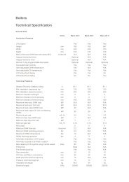
<strong>Johnson</strong> & <strong>Starley</strong> Publication No. ZZ1319-1 June 2008<br />
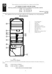
1. GENERAL DESCRIPTION<br />
<strong>PLUME</strong> <strong>MANAGEMENT</strong> <strong>KIT</strong><br />
<strong>Fitting</strong> <strong>Instructions</strong><br />
This kit provides the necessary components to<br />
assemble a plume management system. The kit is<br />
fitted to a flue terminal allowing the inner flue duct to<br />
be extended to a terminal position where the plume<br />
will not cause a nuisance.<br />
ITEM DESCRIPTION QTY<br />
1 1000mm Straight Extension 1<br />
2 500mm Straight Extension 1<br />
3 90˚ Elbow with grille 1<br />
4 90˚ Elbow 1<br />
5 45˚ Elbow 1<br />
6 Adaptor 1<br />
7 Wall Bracket 2<br />
7<br />
6<br />
4<br />
5<br />
Plume Extension<br />
measured to your<br />
required length<br />
Female End<br />
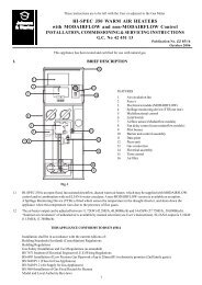
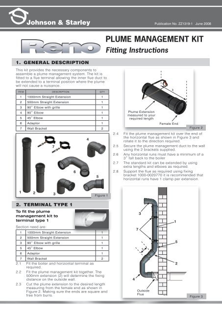
2.4 Fit the plume management kit over the end of<br />
the horizontal flue as shown in Figure 3 and<br />
rotate it to the direction required.<br />
2.5 Secure the plume management duct to the wall<br />
using the 2 brackets supplied.<br />
2.6 Any horizontal runs must have a minimum of a<br />
3˚ fall back to the boiler<br />
2.7 The standard kit can be extended by using<br />
extra lengths and elbows as required.<br />
2.8 Support the flue as required using fixing<br />
bracket 1000-0020770 it is recommended that<br />
horizontal runs have 1 clamp per extension.<br />
x<br />
Figure 2<br />
1 2 3<br />
Figure 1<br />
2. TERMINAL TYPE 1<br />
To fit the plume<br />
management kit to<br />
terminal type 1<br />
3<br />
1<br />
Section need are:<br />
1 1000mm Straight Extension 1<br />
7<br />
2 500mm Straight Extension 1<br />
3 90˚ Elbow with grille 1<br />
5<br />
5 45˚ Elbow 1<br />
x<br />
6 Adaptor 1<br />
7 Wall Bracket 2<br />
2.1 Fit the boiler and horizontal terminal as<br />
required.<br />
2.2 Fit the plume management kit together. The<br />
500mm extension (2) will determine the fixing<br />
distance on the outside wall.<br />
2.3 Cut the plume extension to the desired length<br />
measuring from the female end as shown in<br />
Figure 2. Making sure the ends are square and<br />
free from burrs.<br />
4<br />
Outside<br />
Flue<br />
2<br />
Figure 3
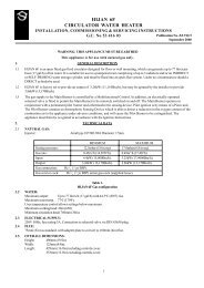
3. TERMINAL TYPE 2<br />
To fit terminal type 2<br />
3.1 Release the screw (1) securing the terminal and<br />
remove the terminal by turning anti-clockwise<br />
To fit the plume management kit to<br />
terminal type 2<br />
Sections needed are:<br />
1 1000mm Straight Extension 1<br />
3 90˚ Elbow with grille 1<br />
4 90˚ Elbow 1<br />
7 Wall Bracket 2<br />
3.6 Release the screw (1) securing the terminal and<br />
remove the terminal by turning anti-clockwise<br />
(2) and pulling it from the flue assembly (3) and<br />
discard.<br />
3.7 Secure the plume management duct to the wall<br />
using the 2 brackets supplied.<br />
3.8 Any horizontal runs must have a minimum of a<br />
3˚ fall back to the boiler.<br />
3.9 The standard kit can be extended by using<br />
extra lengths and elbows as required.<br />
3.10 Support the flue as required using fixing<br />
bracket 1000-0020770 it is recommended that<br />
horizontal runs have 1 clamp per extension.<br />
(2) and pulling it from the flue assembly (3).<br />
3.2 Release the two screws (4) securing the end<br />
part of the terminal reposition this part (5) at an<br />
angle of 45° onto the terminal and secure with<br />
the two screws previously removed.<br />
7<br />
3<br />
1<br />
Note: Do not over tighten the screws.<br />
3.3. Locate the terminal in one of the three<br />
positions, as required, by turning clockwise and<br />
secure in position using the screw previously<br />
removed.<br />
Note: Altering the terminal to give this 45° deflection<br />
reduces the maximum equivalent flue length by<br />
0.9m.<br />
3.4 Fit the plume management kit together.<br />
3.5 Fit the kit over the end of the horizontal flue.<br />
4<br />
Outside<br />
Flue<br />
Figure 4<br />
Rhosili Road, Brackmills, Northampton NN4 7LZ<br />
Main Switchboard Tel: 01604 762881 Fax: 01604 767408<br />
Spares Tel: 01604 707012 Fax: 01604 764879<br />
Service Tel: 01604 707011 Fax: 01604 707017<br />
www.johnsonandstarley.co.uk