Structural Redesigning Of A Cnc Lathe Bed To - Annals of the ...
Structural Redesigning Of A Cnc Lathe Bed To - Annals of the ...
Structural Redesigning Of A Cnc Lathe Bed To - Annals of the ...

Create successful ePaper yourself
Turn your PDF publications into a flip-book with our unique Google optimized e-Paper software.
1. S. Syath ABUTHAKEER, 2. P.V. MOHANRAM, 3. G. Mohan KUMAR<br />
STRUCTURAL REDESIGNING OF A CNC LATHE BED TO<br />
IMPROVE ITS STATIC AND DYNAMIC CHARACTERISTICS<br />
1,2 DEPARTMENT OF MECHANICAL ENGINEERING, PSG COLLEGE OF TECHNOLOGY, COIMBATORE – 641 004, INDIA<br />
3 PARK COLLEGE OF ENGINEERING AND TECHNOLOGY, COIMBATORE, INDIA<br />
ABSTRACT: In <strong>the</strong> past, <strong>the</strong> design <strong>of</strong> CNC machine tools focused on <strong>the</strong>ir functional aspects and was hard to<br />
acquire any resonance with customers. Nowadays, despite <strong>the</strong> needs <strong>of</strong> low price, capabilities withstand at<br />
higher cutting speeds and operate at high acceleration and deceleration with high quality machine, many<br />
customers request good-looking machine. Regarding this, our study aims to provide various form designs <strong>of</strong><br />
machine tool structure with <strong>the</strong> help <strong>of</strong> structural modifications made in CNC machine tool bed. After <strong>the</strong><br />
lightening effect was verified by finite element simulation, scale-down models <strong>of</strong> an original bed and vertical<br />
ribs with hollow bed models were fabricated using rapid prototyping method and tested. The dynamic<br />
characteristics <strong>of</strong> those different form designs <strong>of</strong> <strong>the</strong> bed were analyzed experimentally. Numerical analysis<br />
was done and results were validated with experimental results. Results indicated that <strong>the</strong> cross and<br />
horizontal rib with hollow bed can increase <strong>the</strong> specific stiffness by 8% with 4% weight reduction and its<br />
dynamic performances is also better with increases in <strong>the</strong> first natural frequencies. The modified design is<br />
effective in improving <strong>the</strong> static and dynamic structural performances <strong>of</strong> high speed machine tools.<br />
KEYWORDS: Machine tool bed, Form designs, Stiffness, Natural frequency<br />
� INTRODUCTION<br />
The proper design <strong>of</strong> machine-tool structures requires a thorough knowledge <strong>of</strong> <strong>the</strong>ir forms<br />
designs and properties <strong>of</strong> <strong>the</strong> material, <strong>the</strong> dynamics <strong>of</strong> <strong>the</strong> particular machining process and nature <strong>of</strong><br />
<strong>the</strong> forces involved [1]. Recently, researches have been conducted in <strong>the</strong> field <strong>of</strong> improvement <strong>of</strong><br />
structural design <strong>of</strong> machine tools by improving stiffness and lightening weight which is especially<br />
urgent for <strong>the</strong> structural parts, such as bed, column, worktable, beam and so on [2]. The arrangement<br />
<strong>of</strong> stiffening - ribs in machine tool structures is a key factor for structural stiffness and material<br />
consumption. So <strong>the</strong> lightening design <strong>of</strong> stiffening-ribs is significant for machining performance and<br />
energy saving.<br />
It is generally accepted that <strong>the</strong> precision <strong>of</strong> machine tools is determined by <strong>the</strong>ir static,<br />
dynamic and <strong>the</strong>rmal characteristics. Especially, <strong>the</strong> dynamic characteristics play an important role in<br />
high speed, precision machine tool structures, because vibration during <strong>the</strong> machining process results<br />
in chatter marks on <strong>the</strong> machined surface and thus creates a noisy environment [3].<br />
High static stiffness against bending and torsion, good dynamic characteristics as reflected by<br />
high natural frequency and high damping ratio, ease in production, good long term dimensional<br />
stability, reasonably low coefficient <strong>of</strong> expansion, low cost and low material requirements are <strong>the</strong><br />
basic properties <strong>of</strong> machine tool structures that engineers look for designing and fabricating. However,<br />
from user’s point <strong>of</strong> view, machine tool vibration is an important factor because it adversely affects<br />
<strong>the</strong> quality <strong>of</strong> <strong>the</strong> machined surface. <strong>To</strong> improve both <strong>the</strong> static and dynamic performances, <strong>the</strong><br />
machine tool structures should have high static stiffness and damping. Using ei<strong>the</strong>r higher modulus<br />
material or more material in <strong>the</strong> structure, <strong>the</strong> static stiffness <strong>of</strong> a machine tool may be increased.<br />
But, it is difficult to increases <strong>the</strong> dynamic stiffness <strong>of</strong> a machine tool with <strong>the</strong>se methods and increase<br />
in <strong>the</strong> static stiffness cannot increase it damping property. Material distribution plays on <strong>the</strong> important<br />
role in <strong>the</strong> structural strength and using material in required place can increase static stiffness with<br />
less mass.<br />
Higher cutting speeds can be facilitated only by structures which have high stiffness and good<br />
damping characteristics. The deformation <strong>of</strong> machine tool structures under cutting forces and<br />
structural loads are responsible for <strong>the</strong> poor quality <strong>of</strong> products and which in turn is also aggravated<br />
by <strong>the</strong> noise and vibration produced. In many a situation, it is <strong>the</strong> level <strong>of</strong> deformation and vibration<br />
that determines <strong>the</strong> upper limit on <strong>the</strong> ability <strong>of</strong> <strong>the</strong> machine to produce components with high<br />
precision. All <strong>the</strong>se above said deleterious effects greatly necessitate constant innovations and<br />
continuous research to keep <strong>the</strong>m under check. Increasing structural stiffness could help in avoiding<br />
such problems. <strong>To</strong> increase <strong>the</strong> static stiffness and damping, different form designs can be used.<br />
© copyright FACULTY <strong>of</strong> ENGINEERING ‐ HUNEDOARA, ROMANIA<br />
389
ANNALS OF FACULTY ENGINEERING HUNEDOARA – International Journal <strong>Of</strong> Engineering<br />
The high speed machining process requests completely new demands for <strong>the</strong> mechanism <strong>of</strong> such<br />
processing equipment, as due to <strong>the</strong> process, path speeds exceeding 50m/min can be achieved. In this<br />
field, potential capacities <strong>of</strong> manufacturing processes require a dynamic behavior ten times higher<br />
than <strong>the</strong> conventional machine tools and increased accuracy. This can be solved by <strong>the</strong> systematic<br />
evaluation <strong>of</strong> suitable machine kinematics, by <strong>the</strong> application <strong>of</strong> linear direct drives as well as by mass<br />
reduction <strong>of</strong> <strong>the</strong> axis through light weight components <strong>of</strong> machine tool structure. The requirements <strong>of</strong><br />
high speed machining and ways to improve <strong>the</strong> performance <strong>of</strong> machine tool have been studied [4].<br />
Hollow boxes possess an efficient shape for engineering components due to <strong>the</strong>ir high inherent<br />
bending and torsional rigidities. For example, box-section steel girders are a familiar design <strong>of</strong> beams<br />
in bridges and o<strong>the</strong>r civil engineering structures. Currently, industrial interest exists in <strong>the</strong> use <strong>of</strong> tubes<br />
for <strong>the</strong> moving head <strong>of</strong> a milling machine. The milling machine heads have <strong>the</strong> topology <strong>of</strong> rectangular<br />
tubes with monolithic walls. The overall compliance <strong>of</strong> <strong>the</strong> milling head is partly due to macroscopic<br />
bending <strong>of</strong> <strong>the</strong> tube and partly due to <strong>the</strong> local compliance at <strong>the</strong> supports on <strong>the</strong> guide-rails.<br />
The structural response was analyzed for beams <strong>of</strong> square sections with various internal<br />
topologies: a solid section, a foam-filled tube with monolithic walls, a hollow tube with walls made<br />
from sandwich plates, and a hollow tube with walls reinforced by internal stiffeners. Finite element<br />
analysis was used to validate analytical models for <strong>the</strong> overall stiffness <strong>of</strong> <strong>the</strong> tubes in three-point<br />
bending. Minimum mass designs were obtained as a function <strong>of</strong> <strong>the</strong> overall stiffness, and <strong>the</strong> relative<br />
merits <strong>of</strong> <strong>the</strong> competing topologies were discussed [5].<br />
The weights <strong>of</strong> optimal compression structures <strong>of</strong> several types were studied and estimated.<br />
Minimum weights <strong>of</strong> columns having solid square or circular cross sections were compared with those <strong>of</strong><br />
similar metal foam filled tubes in hollow tubes and tubes whose walls are foam core sandwiches.<br />
Similarly <strong>the</strong> minimum weights <strong>of</strong> wide sandwich compression panels were studied along with those <strong>of</strong><br />
hat-stiffened, solid skin panels and panels in which <strong>the</strong> skins and stiffeners are <strong>the</strong>mselves metal foam<br />
core sandwiches [6].<br />
The minimum deflection and weight designs <strong>of</strong> laminated composite plates were studied.<br />
The finite element method using plate <strong>the</strong>ory was used in conjunction with optimization<br />
routines in order to obtain <strong>the</strong> optimal designs. Various boundary conditions were considered<br />
and results were given for varying aspect ratios and for different loading types [5]. The analysis<br />
for slender beams with a varying cross-section under large non-linear elastic deformation was<br />
conducted. A thickness variation function was derived to achieve optimal - constant maximum bending<br />
stress distribution along <strong>the</strong> beam for inclined end load <strong>of</strong> arbitrary direction [7].<br />
Internal stiffeners support <strong>the</strong> monolithic walls <strong>of</strong> <strong>the</strong> tube and increase <strong>the</strong> local bending<br />
stiffness adjacent to <strong>the</strong> supports. The shape, size, and orientation <strong>of</strong> stiffeners decide <strong>the</strong><br />
improvement in stiffness. The compliance <strong>of</strong> <strong>the</strong> machine tool is one <strong>of</strong> <strong>the</strong> prime factors for deciding<br />
<strong>the</strong> static and dynamic characteristics and thus results <strong>the</strong> quality and performance.<br />
Theoretical analysis and experimental tests showed that <strong>the</strong> size and distribution <strong>of</strong> <strong>the</strong><br />
stiffening ribs could affect <strong>the</strong> stiffness and performance <strong>of</strong> a structure [8]. Kim et al designed<br />
composite-foam-resin concrete sandwich structures for <strong>the</strong> design <strong>of</strong> machine tool [9]. Chang and Lee<br />
et al have fabricated a hybrid column by adhesively bonding glass fabric epoxy composites<br />
laminates to <strong>the</strong> cast iron column. Results show that <strong>the</strong> dynamic characteristic <strong>of</strong> <strong>the</strong> column was<br />
improved [10,11]. Although <strong>the</strong> stiffness <strong>of</strong> machine tool structures can be increased ei<strong>the</strong>r by<br />
employing higher stiffness materials or by increasing <strong>the</strong> sectional modulus <strong>of</strong> structures [12]. In<br />
machine tool, bed forms <strong>the</strong> vital part <strong>of</strong> <strong>the</strong> machine tool on which table and o<strong>the</strong>r relevant parts <strong>of</strong><br />
<strong>the</strong> machine tool move. Many researches were carried out to enhance <strong>the</strong> performance <strong>of</strong> <strong>the</strong> machine<br />
tool bed by improving material property and optimizing structural attributes. It is <strong>the</strong>refore evident<br />
that <strong>the</strong> bed should be sufficiently strong and rigid. Fur<strong>the</strong>r it should be easier to remove <strong>the</strong> chips<br />
produced during machining operation [13].<br />
The main objective <strong>of</strong> this study is to increase <strong>the</strong> structural stiffness, reduce <strong>the</strong> weight and<br />
deformation <strong>of</strong> machine tool bed by designing and fabricating suitable forms, and experimentally<br />
validating <strong>the</strong>m. The conventional distribution was re-arranged by mimicking above structures. Finite<br />
element simulation revealed that <strong>the</strong> modified type bed <strong>of</strong> cross and vertical ribs with hollow structure<br />
possesses better static and dynamic properties when compared with <strong>the</strong> conventional type. Scale-down<br />
models <strong>of</strong> original and modified beds were fabricated via Rapid Proto-typing Manufacturing (RPM). The<br />
results <strong>of</strong> <strong>the</strong> experiment were found to match with that <strong>of</strong> <strong>the</strong> static<br />
and dynamic analysis conducted through analytical results. The results<br />
were encouraging.<br />
� NUMERICAL STATIC ANALYSIS OF FORM DESIGNS OF BED<br />
Before redesigning, <strong>the</strong> existing bed was subjected to static<br />
analysis considering <strong>the</strong> worst case cutting forces. The cutting forces<br />
were based on <strong>the</strong> data obtained from <strong>the</strong> company and <strong>the</strong><br />
parameters at which <strong>the</strong>se cutting forces result are Maximum depth <strong>of</strong><br />
cut: 1mm; Component hardness: 30HRC; Maximum feed <strong>of</strong> X:<br />
0.10mm/rev; Maximum feed <strong>of</strong> Z: 0.2 mm/rev; Spindle working speed:<br />
390<br />
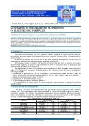
Fig. 1. Loading conditions on<br />
CNC la<strong>the</strong> bed<br />
<strong>To</strong>me IX (Year 2011). Fascicule 3. ISSN 1584 – 2673
ANNALS OF FACULTY ENGINEERING HUNEDOARA – International Journal <strong>Of</strong> Engineering<br />
700 rpm; Spindle power: 3.7 Kw. Apart from <strong>the</strong> cutting forces, four o<strong>the</strong>r static loads along with <strong>the</strong>ir<br />
respective moments were also considered. The loads along with <strong>the</strong>ir respective points <strong>of</strong> application<br />
and <strong>the</strong> supports for <strong>the</strong> bed are shown below in <strong>the</strong> figure 1.<br />
The results <strong>of</strong> <strong>the</strong> FEM analysis<br />
conducted through ANSYS s<strong>of</strong>tware<br />
indicated that <strong>the</strong> portion <strong>of</strong> <strong>the</strong> bed<br />
bearing <strong>the</strong> headstock region suffered<br />
<strong>the</strong> maximum deformation.<br />
� STRUCTURAL MODIFICATION OF MACHINE<br />
TOOL BED<br />
The bed was <strong>the</strong>n considered for<br />
alternate structures and emphases<br />
were laid on retaining <strong>the</strong> existing<br />
manufacturing method and hence<br />
restrict modifications to only structural<br />
redesigning. The static analysis results<br />
were once again scrutinized to identify<br />
locations where excessive, unnecessary<br />
material was present and areas where<br />
material mass could be supplanted by<br />
rib structures.<br />
The presence <strong>of</strong> such rib<br />
structures proved beneficial as <strong>the</strong>y<br />
reduced weight. In <strong>the</strong> above process,<br />
twelve different structural<br />
combinations were identified and each<br />
<strong>of</strong> <strong>the</strong>m was analyzed under <strong>the</strong><br />
prevalent conditions. The models along<br />
with <strong>the</strong> results <strong>of</strong> analyses are<br />
presented. From <strong>the</strong> table 1a and table<br />
1b, it can be observed that two models<br />
i.e. Cross and Horizontal Ribs with<br />
bionic, vertical ribs with hollow display<br />
optimal characteristics. One <strong>of</strong> <strong>the</strong>se<br />
two models, vertical ribs with hollow<br />
was taken up for fur<strong>the</strong>r material<br />
redistribution so that <strong>the</strong> deformation<br />
could be reduced to existing levels<br />
while reducing only weight as shown in<br />
figure 2.<br />
The existing and modified model<br />
<strong>of</strong> machine tool bed was <strong>the</strong>n<br />
fabricated using <strong>the</strong> Rapid Prototyping<br />
Process.<br />
Fig. 2. Modified bed after final modifications<br />
© copyright FACULTY <strong>of</strong> ENGINEERING ‐ HUNEDOARA, ROMANIA<br />
Table 1a. Numerical Static Analysis comparison<br />
<strong>of</strong> various structurally modified bed<br />
Table 1b. Numerical Static Analysis <strong>of</strong> Form design<br />
<strong>of</strong> Machine tool bed<br />
� FEM SIMULATION AND EXPERIMENTS<br />
FEM simulation was carried out using<br />
ANSYS s<strong>of</strong>tware to analyze both <strong>the</strong><br />
conventional and <strong>the</strong> cross and vertical ribs<br />
with hollow bed, in terms <strong>of</strong> static and dynamic<br />
characteristics studies. The 3-D models were<br />
established in a CAD system, Pro/E Wildfire 5.0,<br />
and were imported into ANSYS. The models<br />
were <strong>the</strong>n modified or simplified to meet <strong>the</strong><br />
FEM requirements. The material used was gray<br />
cast iron and <strong>the</strong> material specifications are<br />
listed in table 2. All DOFs <strong>of</strong> bottom surface<br />
were restricted and external loads were applied<br />
to corresponding positions <strong>of</strong> bed.<br />
The deformation distributions and <strong>the</strong><br />
static performances <strong>of</strong> <strong>the</strong> two beds are shown<br />
in Fig. 3a, 3b and results are tabulated in table<br />
3.<br />
391
392<br />
Material<br />
Table 2. Material properties<br />
Elastic Modulus E<br />
(MPa)<br />
Poisson’s<br />
Ratio<br />
ANNALS OF FACULTY ENGINEERING HUNEDOARA – International Journal <strong>Of</strong> Engineering<br />
Density<br />
(kg·m -3 )<br />
Gray cast iron 1.1e5 0.28 7200<br />
ABS 3.2e3 0.35 1200<br />
Fig.3a. Existing bed<br />
Table 3. The comparison <strong>of</strong> simulation results<br />
<strong>Bed</strong><br />
Weight<br />
W(kg)<br />
Deformation<br />
(µm)<br />
Specific<br />
stiffness E/Wd<br />
Original type 100.18 1.619 678.21<br />
Vertical ribs<br />
with hollow bed<br />
96.887 1.5534 730.88<br />
-3.29 -4.05 +7.77<br />
The modified model has a reduced deformation along with<br />
reduction in weight which ultimately increases specific stiffness. Thus<br />
<strong>the</strong> new model proves to be better than <strong>the</strong> existing model by all<br />
means. The maximum displacement <strong>of</strong> vertical ribs with hollow bed is<br />
reduced by about 4.05% with 3.29 % mass reduction, leading to <strong>the</strong><br />
improvement <strong>of</strong> specific stiffness by 7.77%.<br />
NUMERICAL MODAL ANALYSIS OF EXISTING BED<br />
The dynamic performances reflect structure’s resistance to<br />
vibration. So modal analysis was performed to determine <strong>the</strong> first four<br />
order natural frequency and <strong>the</strong> results are shown in table.4. First<br />
mode frequency <strong>of</strong> existing bed is shown in figure 4.<br />
Table 4: Numerical modal analysis<br />
<strong>of</strong> existing bed- First 5 Natural frequencies in Hz<br />
Mode 1 2 3 4<br />
Existing bed -<br />
Natural frequency(Hz)<br />
872.05 1175.88 1280.52 1340.48<br />
Fig.3.b. Modified bed<br />
EXPERIMENTAL MODAL ANALYSIS OF EXISTING BED<br />
Among <strong>the</strong> many different methods to validate <strong>the</strong> CAD model,<br />
<strong>the</strong> natural frequency based evaluation method was adopted. The<br />
natural frequency <strong>of</strong> <strong>the</strong> bed was found experimentally through <strong>the</strong><br />
impact hammer test (ASTM C215-91) using a piezoelectric<br />
Fig.4. Existing bed<br />
accelerometer, NI PXI 1042Q, LabVIEW s<strong>of</strong>tware, etc. The impact pulse<br />
indicating <strong>the</strong> magnitude <strong>of</strong> <strong>the</strong> input force was generated by <strong>the</strong><br />
impact hammer. The frequency domain response was obtained by using<br />
signal analyzer available in sound and vibration toolkit <strong>of</strong> Lab VIEW.<br />
The experimental setup and response <strong>of</strong> <strong>the</strong> bed captured in time and<br />
frequency domains as shown in figure 5.The values <strong>of</strong> natural frequency<br />
thus obtained experimentally were <strong>the</strong>n compared with <strong>the</strong> results <strong>of</strong><br />
modal analysis conducted using ANSYS. The results were found to be<br />
almost similar to each o<strong>the</strong>r. The comparison is shown in table5.<br />
Accelerometer<br />
LabVIEW Program<br />
Cast iron bed<br />
Impact Hammer<br />
FABRICATION OF EXISTING AND MODIFIED BED<br />
Stereolithography was adopted to<br />
fabricate <strong>the</strong> existing and modified bed<br />
to be used in <strong>the</strong> experiments. Taking<br />
cost and operation convenience into<br />
consideration, scale-down bed with<br />
NI PXI 4472<br />
Fig.5. Experimental setup for modal analysis<br />
Existing bed -<br />
Natural<br />
frequency(Hz)<br />
Table 5. Comparison <strong>of</strong> modal frequencies<br />
Mode 1 2 3 4<br />
Analytical 872.05 1175.88 1280.52 1340.48<br />
Experimental 840 1140 1260 1320<br />
scale ratio = 1:5 were produced. The structural dimensions were reduced based on similarity <strong>the</strong>ory to<br />
<strong>To</strong>me IX (Year 2011). Fascicule 3. ISSN 1584 – 2673
ANNALS OF FACULTY ENGINEERING HUNEDOARA – International Journal <strong>Of</strong> Engineering<br />
ensure that <strong>the</strong> mechanical experiments on <strong>the</strong> scaled models could result in <strong>the</strong> same au<strong>the</strong>nticity and<br />
credibility. All loads were calculated conformable to similarity <strong>the</strong>ory. The material <strong>of</strong> <strong>the</strong> models was<br />
ABS (Acrylic Butadiene Styrene) plastic with properties as shown in table3. The SLA (Stereolithography<br />
Apparatus) machine along with <strong>the</strong> fabricated model <strong>of</strong> original and modified bed is as shown in figure<br />
6a and 6b respectively.<br />
Fig. 6a. Stereolithography 6b. Existing and modified model<br />
FEM simulation <strong>of</strong> scale-down models showed that static specific stiffness was increased by 7.77%<br />
and first four order natural frequencies was improved by 75% in average. So static and dynamic<br />
experiments were conducted for both models to evaluate and compare <strong>the</strong>ir performances.<br />
EXPERIMENTAL STATIC ANALYSIS EXISTING AND MODIFIED BED<br />
The setup <strong>of</strong> <strong>the</strong> static test is shown in figure 7. The bottom was fixed with a support. According<br />
to FEM analysis all static loads were applied to corresponding areas. Digital dial-indicators were used to<br />
measure <strong>the</strong> displacement. The measurement <strong>of</strong> each point was repeated five times.<br />
Dial ‐ indicator<br />
Specimen<br />
Figure 7. Experimental setup<br />
EXPERIMENTAL MODAL ANALYSIS OF EXISTING AND MODIFIED BED<br />
Any physical system can vibrate. The frequencies at which vibration naturally occurs, <strong>the</strong> modal<br />
shapes which <strong>the</strong> vibrating system assumes are properties <strong>of</strong> <strong>the</strong> system, and can be determined using<br />
modal analysis. Modal analysis is frequently utilized to abstract <strong>the</strong> modal parameters <strong>of</strong> a system,<br />
including natural frequencies, mode shapes and modal damping ratio. Since <strong>the</strong>se parameters depend<br />
only on <strong>the</strong> system itself but dominate <strong>the</strong> response <strong>of</strong> <strong>the</strong> system to excitations. Modal analysis is <strong>the</strong><br />
fundamental response analysis and has <strong>the</strong>refore gained increasing attentions.<br />
The setup <strong>of</strong> <strong>the</strong> dynamic test is as shown in figure 5. The vibration responses <strong>of</strong> <strong>the</strong> bed <strong>of</strong><br />
different forms were obtained using impact testing, where an instrumented hammer was used to excite<br />
<strong>the</strong> bed. The resulting vibration was measured using a low mass accelerometer. The experimental<br />
setup consisted <strong>of</strong> an impact hammer, a charge accelerometer, signal conditioner and data acquisition<br />
using LabVIEW s<strong>of</strong>tware to record <strong>the</strong> response <strong>of</strong><br />
<strong>the</strong> bed in time and frequency domains. The<br />
frequency domain response was obtained by using<br />
signal analyzer available in sound and vibration<br />
toolkit <strong>of</strong> Lab VIEW. This experimental result <strong>of</strong><br />
<strong>the</strong> modal analysis characteristics <strong>of</strong> <strong>the</strong> existing<br />
and modified bed is shown in figure 8a and 8b.<br />
Fig.8. Modal analysis <strong>of</strong> bed. a. Existing bed b. Modified bed<br />
© copyright FACULTY <strong>of</strong> ENGINEERING ‐ HUNEDOARA, ROMANIA<br />
Table 6. Experimental results comparison- Modal analysis<br />
Mode 1 2 3 4<br />
Existing bed 1175 2210 3400 4450<br />
Vertical ribs<br />
with hollow<br />
bed<br />
Proving ring<br />
Natural<br />
frequency<br />
(Hz) 1542 2100 2150 2189<br />
393
� RESULTS AND DISCUSSIONS<br />
394<br />
ANNALS OF FACULTY ENGINEERING HUNEDOARA – International Journal <strong>Of</strong> Engineering<br />
After three times <strong>of</strong> repeated experiments, <strong>the</strong> measured displacements were averaged. Final<br />
results are listed in table 7. It shows that <strong>the</strong> maximum displacement <strong>of</strong> vertical ribs with hollow bed<br />
model was reduced by about 8.08% with 3.66% mass reduction. The reductions <strong>of</strong> structural weight and<br />
deformation were more significant than <strong>the</strong> results <strong>of</strong> simulation. The possible reasons might be that<br />
<strong>the</strong> bed material in <strong>the</strong> experiments was<br />
Table 7. The comparison <strong>of</strong> simulation results<br />
ABS plastics ra<strong>the</strong>r than cast iron. In any<br />
Weight W Deformation Specific stiffness<br />
<strong>Bed</strong><br />
case, however, <strong>the</strong> vertical ribs with hollow<br />
(kg) (µm)<br />
E/Wd<br />
bed model achieved higher specific Original type 0.138 1.619 14.331<br />
stiffness, indicating more efficient material Vertical ribs with<br />
0.133 1.5534 15.489<br />
distribution than <strong>the</strong> conventional ones.<br />
hollow bed<br />
The modal experiments were<br />
-3.66% -4.05% +8.08%<br />
repeated five times on each bed model. The mode shapes were obtained.<br />
In table 6, <strong>the</strong> first four natural frequencies are listed. The first natural frequencies <strong>of</strong> vertical<br />
ribs with hollow bed one were increased by about 31.23 %. But <strong>the</strong> remaining frequencies were lower<br />
than those <strong>of</strong> original type. However, <strong>the</strong> lowest modal shapes are usually most important for<br />
structural vibration. In addition, <strong>the</strong> first order mode shapes were <strong>the</strong> bending <strong>of</strong> bed along <strong>the</strong> Y<br />
direction, which would be critical for machining precision. So it could be concluded that <strong>the</strong> vertical<br />
ribs with hollow bed type reached better dynamic performance. There are several limitations<br />
associated with <strong>the</strong> scaled-model tests due to <strong>the</strong> different material and technological level. However,<br />
<strong>the</strong> focus is more on <strong>the</strong> relative effectiveness between original and vertical ribs with hollow bed<br />
models. So with <strong>the</strong> results comparison, <strong>the</strong> vertical ribs with hollow bed design have improved <strong>the</strong><br />
static and dynamic performance <strong>of</strong> <strong>the</strong> bed, which is encouraging for fur<strong>the</strong>r study. Casting can be<br />
used for manufacture.<br />
� CONCLUSIONS<br />
(1) Based on <strong>the</strong> configuration principles, <strong>the</strong> existing bed was redesigned to improve <strong>the</strong> static and<br />
dynamic performances. Simulation results show that <strong>the</strong> static and dynamic performances <strong>of</strong> vertical<br />
ribs with hollow bed have been improved.<br />
(2) Scale-down models were used to verify <strong>the</strong> improvements <strong>of</strong> vertical ribs with hollow bed design.<br />
Static and dynamic experiments show that <strong>the</strong> mass and deflection are reduced by 3.66% and 8.08%%<br />
respectively and <strong>the</strong> lower order natural frequencies are increased. Experimental results agree<br />
qualitatively with <strong>the</strong> FEM simulation.<br />
(3) <strong>Structural</strong> vertical ribs with hollow <strong>of</strong>fers a method to improve <strong>the</strong> conventional design <strong>of</strong> machine<br />
structure. Based on structural modifications, ribs parameters and distributions can be fur<strong>the</strong>r<br />
optimized.<br />
� REFERENCES<br />
[1.] S. Kalpakjan, Manufacturing Engineering and Technology, 3rd Edition, Addison-Wesley, Reading, MA, 1995.<br />
[2.] <strong>Structural</strong> Bionic Design and Experimental Verification <strong>of</strong> a Machine <strong>To</strong>ol Column, Ling Zhao, Wu-yi Chen, Jianfeng<br />
Ma, Yong-bin Yang, Journal <strong>of</strong> Bionic Engineering Suppl. (2008) 46–52.<br />
[3.] Damping characteristics <strong>of</strong> composite hybrid spindle covers for high speed machine tools Jung Do Suha, Seung<br />
Hwan Changa, Dai Gil Leea, Jin Kyung Choib and Bo Seon Parkc , Journal <strong>of</strong> Materials Processing Technology,<br />
Volume 113, Issues 1-3, 15 June (2001), Pages 178-183.<br />
[4.] Heisel, M Gringel, “Machine <strong>To</strong>ol Design Requirements for High Speed Machining”, in CIRP <strong>Annals</strong>-Manufacturing<br />
Technology, volume 45, Issue 1(1996), Pages 389-392.<br />
[5.] S.P. Mai, N.A. Fleck, T.J. Lu, “Optimal design <strong>of</strong> box-section sandwich beams in three-point bending”, in<br />
International Journal <strong>of</strong> Solids and Structures, vol. 44, (2007), pp. 4742-4769<br />
[6.] Bernard Budiansky, “On <strong>the</strong> minimum weights <strong>of</strong> compression structures”, in International Journal <strong>of</strong> Solids and<br />
Structures, volume 36, (1999), pp. 3677-3708.<br />
[7.] Mark Walker, Talmon Reiss & Sarp Adalib, “Optimal design <strong>of</strong> symmetrically laminated plates for minimum<br />
deflection and weight”, in Composite structures, volume 39, (1997) Pages 337-346.<br />
[8.] Liu J S, Hollaway L. Design optimization composite panel structures with stiffening ribs under multiple loading<br />
cases. Computers and Structures, (2000), 78, 637-647.<br />
[9.] Kim D I., Jung S C, Lee J E. Parametric study on design <strong>of</strong> composite-foam-resin concrete sandwich structures for<br />
precision machine tool structures. Composite Structures, (2006), 75, 408-414.<br />
[10.] Chang S H, Kim P J, Lee D G, Chol J K. Steel-composite hybrid headstock for high-precision grinding machine.<br />
Composite Structures, (2001), 53, 1-8.<br />
[11.] Lee D G, Chang S H, Kim H S. Damping improvement <strong>of</strong> machine tool columns with polymer matrix fiber<br />
composite material. Composite Structures, (1998), 43,155-63.<br />
[12.] Jung Do Suh and Dai Gil Lee, “Design and manufacture <strong>of</strong> hybrid polymer concrete bed for high-speed CNC milling<br />
machine”, International journal <strong>of</strong> Mechanical Material Design, volume 4, (2008), Pages 113-121.<br />
[13.] Myo Min Zaw “Strength Analysis <strong>of</strong> <strong>Bed</strong>ways for CNC <strong>La<strong>the</strong></strong> Machine” GMSARN International Conference on<br />
Sustainable Development: Issue and Prospects for <strong>the</strong> GMS 12-14 Nov.(2008).<br />
<strong>To</strong>me IX (Year 2011). Fascicule 3. ISSN 1584 – 2673