Ordering codes
Ordering codes
Ordering codes

Create successful ePaper yourself
Turn your PDF publications into a flip-book with our unique Google optimized e-Paper software.
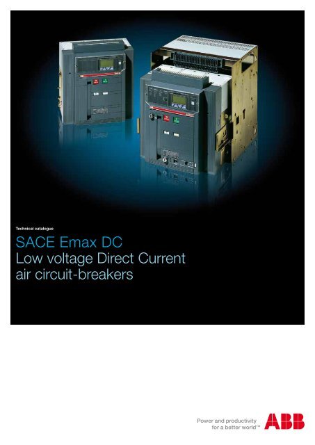
Technical catalogue<br />
SACE Emax DC<br />
Low voltage Direct Current<br />
air circuit-breakers
Index<br />
SACE Emax DC circuit-breakers ............................................................................................. 2<br />
SACE Emax DC switch-disconnectors .................................................................................... 6<br />
Versions and connections ....................................................................................................... 7<br />
Dissipated powers ................................................................................................................... 8<br />
Temperature derating .............................................................................................................. 9<br />
Protection trip units and trip curves ...................................................................................... 11<br />
Accessories ........................................................................................................................... 25<br />
Overall dimensions ................................................................................................................ 26<br />
Electric wiring diagrams ........................................................................................................ 35<br />
Selection Emax DC ................................................................................................................ 44<br />
<strong>Ordering</strong> <strong>codes</strong> ..................................................................................................................... 50<br />
<strong>Ordering</strong> examples ................................................................................................................ 88<br />
ABB SACE 1<br />
1SDC200012D0902
2<br />
1SDC200012D0902<br />
SACE Emax DC circuit-breakers<br />
The SACE Emax range of low voltage circuit-breakers is completed by the new SACE Emax<br />
DC series of circuit-breakers for direct current applications complying with the IEC60947-<br />
2 Standard. Thanks to the exclusive technology applied to the new SACE PR123/DC and<br />
PR122/DC trip units, the SACE Emax DC range allow all installation requirements to be met<br />
and protection up to 1000V DC / 5000A.<br />
With connection of three interruption poles in series, the rated voltage which can be reached<br />
is 750V DC, whereas with four poles in series this rises to 1000V DC.<br />
The withdrawable circuit-breakers must be associated with the fixed parts in a special version<br />
for applications at 750/1000V DC.<br />
Common data<br />
Voltages<br />
Rated service voltage Ue [V–] 1000<br />
Rated insulation voltage Ui [V] 1000<br />
Rated impulse withstand voltage Uimp [kV] 12<br />
Operating temperature [°C] -25....+70<br />
Storage temperature [°C] -40....+70<br />
Number of poles 3 - 4<br />
Versions Fixed - Withdrawable<br />
E2 E3 E4 E6<br />
Levels of performance B N N H S H H<br />
Rated uninterrupted current (at 40 °C) Iu [A] 800 800<br />
[A] 1000 1000<br />
[A] 1250 1250<br />
[A] 1600 1600 1600 1600 1600<br />
[A] 2000 2000 2000<br />
[A] 2500 2500 2500<br />
[A] 3200 3200 3200<br />
[A] 4000<br />
[A] 5000<br />
Rated ultimate short-circuit breaking capacity Icu according to the<br />
application network<br />
See pages 3, 4 and 5<br />
Rated service short-circuit breaking capacity Ics [%Icu]<br />
Rated short-time withstand current Icw (0.5s)<br />
[kA] 100% 100% 100% 100% 100% 100% 100%<br />
@ 500 V DC (3p) [kA] 35 50 60 65 75 100 100<br />
@ 750 V DC (3p) [kA] 25 25 40 40 65 65 65<br />
@ 750 V DC (4p) [kA] 25 40 50 50 65 65 65<br />
@ 1000 V DC (4p) [kA] 25 25 35 40 50 65 65<br />
Rated short-circuit making capacity Icm [%Icu] [kA] 100% 100% 100% 100% 100% 100% 100%<br />
Category of use (according to CEI EN 60947-2) B B B B B B B<br />
Isolation behaviour (according to CEI EN 60947-2)<br />
Overcurrent protection<br />
� � � � � � �<br />
Electronic trip units for DC applications<br />
Operating times<br />
� � � � � � �<br />
Closing time (max) [ms] 80 80 80 80 80 80 80<br />
Breaking time for I
Insulated network (1)<br />
+<br />
-<br />
Rated voltage (Ue) ≤ 500 ≤ 750 ≤ 1000<br />
L<br />
O<br />
A<br />
D<br />
LOAD -<br />
LOAD +<br />
+ -<br />
LOAD +<br />
+ -<br />
isolation � � � �<br />
protection � � � �<br />
PR122/DC � � � �<br />
PR123/DC � � � �<br />
Icu (2) [kA] [kA] [kA] [kA]<br />
800<br />
SACE Emax DC circuit-breakers<br />
Rated ultimate short-circuit breaking capacity Icu<br />
according to the type of network<br />
E2<br />
B<br />
1000<br />
1250<br />
1600<br />
35 25 25 25<br />
N 1600<br />
800<br />
1000<br />
50 25 40 25<br />
N<br />
1250<br />
1600<br />
60 40 50 35<br />
E3<br />
2000<br />
2500<br />
1600<br />
H<br />
65 (3) 2000<br />
2500<br />
1600<br />
40 50 40<br />
E4<br />
S<br />
2000<br />
2500<br />
3200<br />
75 65 65 50<br />
H 3200<br />
3200<br />
100 65 65 65<br />
E6 H 4000<br />
5000<br />
100 65 65 65<br />
(1) the possibility of a double earth fault is considered negligible with this type of pole connections. For further information, see QT5: “ABB circuit-breakers for direct current applications”.<br />
(2) Icu with L/R = 15ms according to IEC 60946-2 Standard. For Icu with L/R = 5ms and L/R = 30ms, ask ABB.<br />
(3) 85kA only if supplied from below and specifying the following extracode at the ordering stage: 1SDA067148R1. Ics=65kA.<br />
ABB SACE 3<br />
LOAD -<br />
1SDC200012D0902
Network with earthed negative polarity (1)<br />
4<br />
+<br />
-<br />
1SDC200012D0902<br />
L<br />
O<br />
A<br />
D<br />
SACE Emax DC circuit-breakers<br />
Rated ultimate short-circuit breaking capacity Icu<br />
according to the type of network<br />
Rated voltage (Ue) ≤ 500 (2)<br />
LOAD -<br />
LOAD +<br />
+ -<br />
isolation � �<br />
protection � �<br />
PR122/DC � �<br />
PR123/DC � �<br />
type of fault (3) a b a b<br />
poles in series affected by the fault 3 2 4 3<br />
Icu (4) [kA] [kA]<br />
E2<br />
B<br />
800<br />
1000<br />
1250<br />
1600<br />
35 20 35 35<br />
N 1600<br />
800<br />
1000<br />
50 25 50 50<br />
N<br />
1250<br />
1600<br />
60 30 60 60<br />
E3<br />
2000<br />
2500<br />
1600<br />
H<br />
65 (5) 40 65 (5) 65 (5)<br />
2000<br />
2500<br />
1600<br />
E4<br />
S<br />
2000<br />
2500<br />
3200<br />
100 50 100 100<br />
H 3200<br />
3200<br />
100 65 100 100<br />
E6 H 4000<br />
5000<br />
100 65 100 100<br />
(1) for networks with positive earthed polarity, ask ABB.<br />
(2) for higher voltages, ask ABB.<br />
(3) for further information, see QT5: “ABB circuit-breakers for direct current applications”.<br />
(4) Icu with L/R = 15ms according to IEC 60946-2 Standard. For Icu with L/R = 5ms and L/R = 30ms, ask ABB.<br />
(5) 85kA only if supplied from below and specifying the following extracode at the ordering stage: 1SDA067148R1. Ics=65kA.<br />
ABB SACE
Network with the median point earthed<br />
+<br />
-<br />
Rated voltage (Ue) ≤ 500 ≤ 500 ≤ 750 ≤ 1000<br />
2<br />
2<br />
L<br />
O<br />
A<br />
D<br />
LOAD -<br />
LOAD +<br />
+ -<br />
PR122/DC - - - -<br />
PR123/DC � � � �<br />
type of fault a b c a b c a b c a b c<br />
poles in series affected by the fault 3 2 (U/2) 1 (U/2) 4 2 (U/2) 2 (U/2) 4 2 (U/2) 2 (U/2) 4 2 (U/2) 2 (U/2)<br />
Icu (1) [kA] [kA] [kA] [kA]<br />
800<br />
E2<br />
B<br />
1000<br />
1250<br />
1600<br />
35 35 18 35 35 35 25 25 25 25 25 25<br />
N 1600<br />
800<br />
1000<br />
50 50 25 50 50 50 40 40 40 25 25 25<br />
N<br />
1250<br />
1600<br />
60 60 30 60 60 60 50 50 50 35 35 35<br />
E3<br />
2000<br />
2500<br />
1600<br />
H<br />
65 (2) 65 40 65 (2) 65 (2) 65 (2) 2000<br />
2500<br />
1600<br />
50 50 50 40 40 40<br />
E4<br />
S<br />
2000<br />
2500<br />
3200<br />
75 75 35 75 75 75 65 65 65 50 50 50<br />
H 3200<br />
3200<br />
100 100 50 100 100 100 65 65 65 65 65 65<br />
E6 H 4000<br />
5000<br />
100 100 65 100 100 100 65 65 65 65 65 65<br />
(1) Icu with L/R = 15ms according to IEC 60946-2 Standard. For Icu with L/R = 5ms and L/R = 30ms, ask ABB.<br />
(2) 85kA only if supplied from below and specifying the following extracode at the ordering stage: 1SDA067148R1. Ics=65kA.<br />
ABB SACE 5<br />
1SDC200012D0902
6<br />
1SDC200012D0902<br />
SACE Emax switch-disconnectors<br />
ABB SACE has developed the SACE Emax/E MS range of switch-disconnectors for direct current<br />
applications up to 1000V complying with the international IEC60947-3 Standard. These<br />
circuit-breakers are particularly suitable for use as bus-ties or main switch-disconnectors in<br />
direct current plants, such as applications in the field of electric traction.<br />
The range makes it possible to cover any installation requirement up to 1000V DC / 6300A.<br />
The circuit-breakers are available in the fixed or withdrawable version and in the three-pole<br />
or four-pole version.<br />
With connection of three breaking poles in series, the rated voltage which can be reached is<br />
750V DC, whereas with four poles in series this rises to 1000V DC.<br />
The switch-disconnectors in the SACE Emax/E MS range keep all the overall dimensions<br />
and fixing points of the circuit-breakers of the standard range unchanged. The withdrawable<br />
circuit-breakers must be associated with the fixed parts in a special version for applications<br />
at 750/1000V DC.<br />
E1B/E MS E2N/E MS E3H/E MS E4H/E MS E6H/E MS<br />
Rated current (at 40 °C) Iu [A] 800 1250 1250 3200 5000<br />
[A] 1250 1600 1600 4000 6300<br />
[A] 2000 2000<br />
[A] 2500<br />
[A] 3200<br />
Poles 3 4 3 4 3 4 3 4 3 4<br />
Rated service voltage Ue [V] 750 1000 750 1000 750 1000 750 1000 750 1000<br />
Rated insulation voltage Ui [V] 1000 1000 1000 1000 1000 1000 1000 1000 1000 1000<br />
Rated impulse withstand voltage Uimp [kV] 12 12 12 12 12 12 12 12 12 12<br />
Rated short-time withstand current Icw (1s) [kA] 20 20* 25 25* 40 40* 65 65 65 65<br />
Rated making capacity Icm [%Icw] 100 100 100 100 100 100 100 100 100 100<br />
Note: By means of an extreme protection relay with maximum timing of 500 ms, the Icu breaking capacity is the same as the Icw value (1s).<br />
* The performances at 750 V are:<br />
for E1B/E MS Icw=25kA<br />
for E2N/E MS Icw=40kA<br />
for E3H/E MS Icw=50kA<br />
ABB SACE
Versions and connections<br />
Versions and connections<br />
The Emax DC circuit-breakers are available in the fixed or withdrawable, three-pole or fourpole<br />
versions.<br />
All Emax circuit-breakers for direct current have several poles in series involved in breaking the<br />
fault, so they are mounted on the circuit-breaker terminals of the special connection busbars,<br />
known as “U connections”.<br />
Selection of the power supply side, from the lower or upper terminals, must only be made at<br />
the time of ordering and cannot be modified later by the customer.<br />
The fixed circuit-breakers are fitted with vertical terminals, whereas it is possible to select<br />
between vertical and horizontal terminals for circuit-breakers in the withdrawable version,.<br />
Fixed circuit-breaker<br />
Vertical rear terminals<br />
Power supply from the lower terminals Power supply from the upper terminals<br />
Withdrawable circuit-breaker<br />
Vertical rear terminals<br />
Power supply from the lower terminals Power supply from the upper terminals<br />
Horizontal rear terminals<br />
Power supply from the lower terminals Power supply from the upper terminals<br />
ABB SACE 7<br />
1SDC200012D0902
8<br />
1SDC200012D0902<br />
Dissipated powers<br />
The dissipated powers for Emax DC circuit-breakers are given below according to:<br />
- range;<br />
- trip unit;<br />
- version;<br />
- number of poles;<br />
- Iu.<br />
Emax DC dissipated powers [W]<br />
E2<br />
E3<br />
E4<br />
E6<br />
Iu [A]<br />
Trip unit Version poles 800 1000 1250 1600 2000 2500 3200 4000 5000<br />
PR122/DC<br />
PR123/DC<br />
PR122/DC<br />
PR123/DC<br />
PR122/DC<br />
PR123/DC<br />
PR122/DC<br />
PR123/DC<br />
F 3p 42 60 94 136<br />
W 3p 66 98 152 232<br />
F 4p 51 75 117 174<br />
W 4p 83 125 195 302<br />
F 3p 54 113 176 156<br />
W 3p 78 113 176 252<br />
F 4p 64 140 219 195<br />
W 4p 96 140 219 323<br />
F 3p 32 61 95 123 216 338<br />
W 3p 47 69 108 207 248 388<br />
F 4p 38 87 123 184 288 450<br />
W 4p 59 87 136 205 320 500<br />
F 3p 50 68 106 138 216 338<br />
W 3p 60 84 131 179 280 438<br />
F 4p 55 86 134 184 288 450<br />
W 4p 65 102 159 225 352 550<br />
F 3p 120 188 271<br />
W 3p 195 305 463<br />
F 4p 136 234 348<br />
W 4p 236 391 604<br />
F 3p 150 234 312<br />
W 3p 225 352 504<br />
F 4p 180 281 389<br />
W 4p 280 438 645<br />
F 3p 154 304 475<br />
W 3p 276 496 775<br />
F 4p 246 384 600<br />
W 4p 410 640 1000<br />
F 3p 236 368 575<br />
W 3p 358 560 875<br />
F 4p 287 448 700<br />
W 4p 451 704 1100<br />
ABB SACE
Temperature derating<br />
The following graphs show derating as the temperature increases for Emax DC circuit-breakers.<br />
Iu [A]<br />
Iu [A]<br />
2000<br />
1500<br />
1000<br />
500<br />
0<br />
10 20 30 40 50 55 60 70<br />
E2 DC 800 1000 1250 1600<br />
°C % A % A % A % A<br />
10 100% 800 100% 1000 100% 1250 100% 1600<br />
20 100% 800 100% 1000 100% 1250 100% 1600<br />
30 100% 800 100% 1000 100% 1250 100% 1600<br />
40 100% 800 100% 1000 100% 1250 100% 1600<br />
50 100% 800 100% 1000 100% 1250 100% 1600<br />
55 100% 800 100% 1000 100% 1250 100% 1600<br />
60 100% 800 100% 1000 100% 1250 98% 1567<br />
70 100% 800 100% 1000 100% 1250 94% 1500<br />
3000<br />
2500<br />
2000<br />
1500<br />
1000<br />
500<br />
0<br />
E2 DC<br />
E3 DC 800 1000 1250 1600 2000 2500<br />
°C % A % A % A % A % A % A<br />
10 100% 800 100% 1000 100% 1250 100% 1600 100% 2000 100% 2500<br />
20 100% 800 100% 1000 100% 1250 100% 1600 100% 2000 100% 2500<br />
30 100% 800 100% 1000 100% 1250 100% 1600 100% 2000 100% 2500<br />
40 100% 800 100% 1000 100% 1250 100% 1600 100% 2000 100% 2500<br />
50 100% 800 100% 1000 100% 1250 100% 1600 100% 2000 100% 2500<br />
55 100% 800 100% 1000 100% 1250 100% 1600 100% 2000 100% 2500<br />
60 100% 800 100% 1000 100% 1250 100% 1600 100% 2000 100% 2500<br />
70 100% 800 100% 1000 100% 1250 100% 1600 100% 2000 94% 2350<br />
ABB SACE 9<br />
°C<br />
E3 DC<br />
10 20 30 40 50 55 60 70<br />
°C<br />
800<br />
1000<br />
1250<br />
1600<br />
800<br />
1000<br />
1250<br />
1600<br />
2000<br />
2500<br />
1SDC200012D0902
10<br />
1SDC200012D0902<br />
Temperature derating<br />
Iu [A]<br />
Iu [A]<br />
3500<br />
3000<br />
2500<br />
2000<br />
1500<br />
1000<br />
500<br />
0<br />
10 20 30 40 50 55 60 70<br />
E4 DC 1600 2000 2500 3200<br />
°C % A % A % A % A<br />
10 100% 1600 100% 2000 100% 2500 100% 3200<br />
20 100% 1600 100% 2000 100% 2500 100% 3200<br />
30 100% 1600 100% 2000 100% 2500 100% 3200<br />
40 100% 1600 100% 2000 100% 2500 100% 3200<br />
50 100% 1600 100% 2000 100% 2500 100% 3200<br />
55 100% 1600 100% 2000 100% 2500 100% 3200<br />
60 100% 1600 100% 2000 100% 2500 100% 3200<br />
70 100% 1600 100% 2000 100% 2500 97% 3100<br />
6000<br />
5000<br />
4000<br />
3000<br />
2000<br />
1000<br />
0<br />
E4 DC<br />
E6 DC 3200 4000 5000<br />
°C<br />
E6 DC<br />
10 20 30 40 50 55 60 70<br />
°C<br />
°C % A % A % A<br />
0 100% 3200 100% 4000 100% 5000<br />
10 100% 3200 100% 4000 100% 5000<br />
20 100% 3200 100% 4000 100% 5000<br />
30 100% 3200 100% 4000 100% 5000<br />
40 100% 3200 100% 4000 100% 5000<br />
50 100% 3200 100% 4000 100% 5000<br />
55 100% 3200 100% 4000 100% 5000<br />
60 100% 3200 100% 4000 100% 5000<br />
70 100% 3200 100% 4000 96% 4800<br />
1600<br />
2000<br />
2500<br />
3200<br />
3200<br />
4000<br />
5000<br />
ABB SACE
Protection trip units and trip curves<br />
PR122/DC<br />
Characteristics<br />
PR122/DC is the new electronic trip unit for the Emax DC series. The vast range of protection<br />
functions, together with the wide variety of trip thresholds and times, make them suitable<br />
for protection of insulated networks or networks with earthed negative polarity. Consulting<br />
information about the unit and its programming is particularly simple and intuitive thanks to<br />
the LCD graphic display.<br />
The PR122/DC trip unit offers the following protection functions:<br />
• overload (L);<br />
• selective short-circuit (S);<br />
• thermal memory for L and S (cable protection);<br />
• instantaneous short-circuit (I);<br />
• overtemperature (OT);<br />
• zone selectivity for S;<br />
• load control (K);<br />
• starting threshold.<br />
ABB SACE 11<br />
1SDC200012D0902<br />
1SDC200607F0001
Protection functions and setting values - PR122/DC<br />
Function Trip<br />
threshold<br />
12<br />
OT<br />
1SDC200012D0902<br />
Threshold<br />
step<br />
Protection against<br />
overload I1= 0.4...1 x In 0.01 x In<br />
Tolerance (2) Trip unit between<br />
1.05 and 1.3 x I1<br />
Selective protection<br />
against short-circuit<br />
I2= 0.6...10 x In 0.1 x In<br />
Tolerance (2) ± 7%, If ≤ 6 x In<br />
± 10%, If > 6 x In<br />
I2= 0.6...10 x In 0.1 x In<br />
Tolerance (2) ± 7%, If ≤ 6 x In<br />
± 10%, If > 6 x In<br />
Trip time Time<br />
step<br />
Disabling Relation<br />
t=f(I)<br />
(1) The minimum trip value is 0.5 s, regardless of the type of curve set<br />
(2) These tolerances are valid in the following hypotheses:<br />
- trip unit supplied entirely by the voltage module and/or auxiliary power supply (without start-up)<br />
- trip time set ≥ 100 ms<br />
For all cases not contemplated by the above hypotheses, the following tolerance values are valid:<br />
Thermal<br />
memory<br />
Zone<br />
selectivity<br />
With current If = 3 x I1<br />
t1= 3 s...102 s (1) 3 s – IEC60255-8 � –<br />
± 10%, If ≤ 6 x In<br />
± 20%, If > 6 x In<br />
With current If > I2<br />
t2= 0.05 s...0.35 s<br />
t2sel= 0.04 s...0.2 s<br />
The best of the two data:<br />
± 10% or ± 40 ms<br />
With current If ≥ 10 x In<br />
t2= 0.05 s...0.35 s<br />
± 15%, If ≤ 6 x In<br />
± 20%, If > 6 x In<br />
0.01 s<br />
0.01 s<br />
� t=k – �<br />
0.01 s � t=k/I 2 � –<br />
Protection against<br />
instantaneous<br />
short-circuit I3= 1.5...10 x In 0.1 x In Instantaneous – � t=k – –<br />
Tolerance (2) ± 10% ≤ 30 ms<br />
Protection trip units and trip curves<br />
PR122/DC<br />
Protection against<br />
overtemperature Cannot be set – Instantaneous – – t=k – –<br />
Trip threshold Trip time<br />
L Trip between 1.05 and 1.25 x I1 ± 20%<br />
S ± 10% ± 20%<br />
I ± 15% ≤ 60ms<br />
ABB SACE
With plant voltages higher than or equal to 100V, the PR122/DC electronic trip unit guarantees<br />
protection without the need of an auxiliary power supply (24V DC).<br />
The PR122/DC electronic trip unit can, in fact, always be equipped with the PR120/V module<br />
able to supply the trip unit with plant voltages between 250V DC and 1000V DC.<br />
For voltages between 100V DC and 250V DC, it is necessary to request the PR120/LV module,<br />
specifying the extracode 1SDA066223R1.<br />
The following table shows the cases where it is possible to use of the measurement modules<br />
(PR120/V and PR120/LV):<br />
Ue [V] 12 100 250 1000<br />
PR120/LV: PR120/LV + Vaux PR120/LV NO<br />
PR120/V: PR120/V + Vaux PR120/V + Vaux PR120/V<br />
When there is an auxiliary power supply, see the table below for the overall consumption values.<br />
PR122/DC PR120/D-M PR120/K<br />
Auxiliary power supply<br />
(galvanically insulated)<br />
24V DC ± 20% from PR122/DC from PR122/DC<br />
Maximum ripple 5%<br />
Inrush current @ 24V ~10A for 5 ms<br />
Rated power @ 24V ~3 W +1.5 W +1.5 W<br />
When Emax DC circuit-breakers are used in plants with capacitor banks with possible backto-back<br />
inrush currents ≥ 3xIn, it is necessary to use a 24V DC galvanically insulated auxiliary<br />
power supply.<br />
The range of Emax DC circuit-breakers is normally supplied with power input from the lower<br />
terminals, i.e. the PR120/V-PR120/LV internal connection is on the lower terminals, whereas<br />
the U connections are on the upper terminals:<br />
3D rear view<br />
–<br />
+<br />
For power input to the upper terminals, refer to the Code Section for ordering.<br />
Front view<br />
Protection is guaranteed even when the electronic trip unit is not powered thanks to the PR120/DC<br />
module which the PR122/DC is always fitted with.<br />
ABB SACE 13<br />
1SDC200012D0902
Functions L-S-I<br />
Functions L-S-I<br />
14<br />
1SDC200012D0902<br />
Protection trip units and trip curves<br />
PR122/DC<br />
t = k<br />
I 2 t = k<br />
ABB SACE<br />
1SDC200608F0001<br />
1SDC200609F0001
Protection trip units and trip curves<br />
PR123/DC<br />
Characteristics<br />
With the PR123/DC electronic protection trip unit, the range of trip units available for the Emax<br />
DC series of circuit-breakers is completed.<br />
PR123/DC is a high-performing trip unit capable of carrying out a complete set of protections,<br />
measurements, indications, data storage and circuit-breaker control functions.<br />
PR123/DC not only offers protection but also measurement of current and voltage of both<br />
polarities (+ and -), therefore being suitable for any type of network.<br />
The front interface of the unit, common to PR122/DC, is extremely simple thanks to the aid<br />
of the LCD graphic display.<br />
The PR123/DC trip unit offers the following protection functions:<br />
• overload (L);<br />
• selective short-circuit (S);<br />
• thermal memory for L and S (cable protection);<br />
• instantaneous short-circuit (I);<br />
• earth fault with adjustable delay (G);<br />
• polarity unbalance (U);<br />
• protection against overtemperature (OT);<br />
• load control (K);<br />
• undervoltage (UV);<br />
• overvoltage (OV);<br />
• active power reversal (RP);<br />
• double set of parameters (Dual Setting);<br />
• zone selectivity for S and G;<br />
• starting thresholds for protection S and I.<br />
ABB SACE 15<br />
1SDC200012D0902<br />
1SDC200610F0001
Protection functions and setting values - PR123/DC<br />
Function Trip<br />
threshold<br />
16<br />
U<br />
OT<br />
UV<br />
OV<br />
RP<br />
(1) The minimum trip value is 0.5 s, regardless of the type of curve set<br />
(2) These tolerances are valid with the following hypothesis:<br />
- trip unit supplied from the voltage module and/or auxiliary power supply<br />
(without start-up)<br />
- trip time set ≥ 100 ms<br />
1SDC200012D0902<br />
Threshold<br />
step<br />
Protection against<br />
overload I1 = 0,4...1 x In 0.01 x In<br />
Tolerance (2) Trip between<br />
1.05 and 1.3 x I1<br />
Selective protection<br />
against short-circuit<br />
I2 = 0.6...10 x In 0,1 x In<br />
Tolerance (2) ± 7% If ≤ 6 x In<br />
± 10% If > 6 x In<br />
I2 = 0.6...10 x In 0,1 x In<br />
Tolerance (2) ± 7% If ≤ 6 x In<br />
± 10% If > 6 x In<br />
Selective protection<br />
against short-circuit I2 = 0.6...10 x In 0,1 x In<br />
Tolerance (2) ± 7% If ≤ 6 x In<br />
± 10% If > 6 x In<br />
Trip time Time<br />
step<br />
Disabling Relation<br />
t=f(I)<br />
Thermal<br />
memory<br />
Zone<br />
selectivity<br />
With current I = 3 x I1<br />
t1 = 3 s...102 s (1) 3 s – IEC60255-8 � –<br />
± 10% If ≤ 6 x In<br />
± 20% If > 6 x In<br />
With current I > I2<br />
t2 = 0.05 s...0.35 s<br />
t2sel = 0.04 s...0.2 s<br />
The best of the two data:<br />
± 10% or ± 40 ms<br />
With current I = 10 x I1<br />
t2 = 0.05 s...0.35 s<br />
± 15% If ≤ 6 x In<br />
± 20% If > 6 x In<br />
0.01 s<br />
0.01 s<br />
� t=k – �<br />
0.01 s � t=k/I 2 � –<br />
With current I > I2<br />
t2 = 0.05 s...0.35 s 0.01 s � t=k – �<br />
The best of the two data:<br />
± 10% or ± 40 ms<br />
Protection against<br />
instantaneous<br />
short-circuit I3 = 1.5...10 x In 0.1 x In Instantaneous – � t=k – –<br />
Tolerance (2) ± 10% ≤ 30 ms<br />
Protection against<br />
earth fault<br />
Tolerance (2) ± 7%<br />
I4 = 0.2...1 x In 0.02 x In<br />
With current I > I4<br />
t4 = 0.1 s...1 s<br />
t4sel = 0.04 s...0,2 s<br />
The best of the two data:<br />
± 10% or ± 40 ms<br />
I4 = 0.2...1 x In 0.02 x In t4 = 0.1 s...1 s<br />
(with I=4xI4)<br />
0.05 s<br />
0.01 s<br />
� t=k – �<br />
0.05 s � t=k/I 2 – –<br />
Tolerance (2) ± 7% ± 15%<br />
Protection against I6 = 5%...90% 5% t6 = 0.5 s...60 s 0.5 s � t=k – –<br />
phase unbalance<br />
The best of the two data:<br />
Tolerance (2) ± 10% ± 20% or ± 100 ms<br />
Protection against<br />
overtemperature Cannot be set – Instantaneous – – t=k – –<br />
Undervoltage<br />
protection<br />
Tolerance (2) ± 5%<br />
Overvoltage<br />
protection<br />
Tolerance (2) ± 5%<br />
Protection against<br />
reversal of power<br />
Tolerance (2) ± 10%<br />
Protection trip units and trip curves<br />
PR123/DC<br />
U8 = 0.5...0.95 x Un 0.01 x In With voltage U < U8<br />
t8 = 0.1 s...5 s<br />
The best of the two data:<br />
± 20% or ± 40 ms<br />
U9 = 1.05...1.2 x Un 0.01 x In With voltage U < U9<br />
t9 = 0.1 s...5 s<br />
The best of the two data:<br />
± 20% or ± 40 ms<br />
P11 = -0.3...-0.1 x Pn 0.02 x Pn At power P < P11<br />
t11 = 0.5 s...25 s<br />
The best of the two data:<br />
± 10% or ± 100 ms<br />
0.1 s � t=k – –<br />
0.1 s � t=k – –<br />
0.1 s � t=k – –<br />
For all cases not contemplated by the above hypothesis, the following tolerance values are valid:<br />
Trip threshold Trip time<br />
L Trip between 1.05 and 1.3 x I1 ± 20%<br />
S ± 10% ± 20%<br />
I ± 15% ≤ 60ms<br />
G ± 15% ± 20%<br />
Altri ± 20%<br />
ABB SACE
With plant voltages higher than or equal to 100V, the PR123/DC electronic trip unit guarantees<br />
protection without the need of an auxiliary power supply (24V DC).<br />
The PR123/DC electronic trip unit is, in fact, always fitted with the PR120/V module able to<br />
supply the trip unit with plant voltages between 250V DC and 1000V DC.<br />
For voltages between 100V DC and 250V DC, it is necessary to request the PR120/LV module,<br />
specifying the extracode 1SDA066223R1.<br />
The following table shows the possible cases of use of the measurement modules (PR120/V<br />
and PR120/LV):<br />
Ue [V] 12 100 250 1000<br />
PR120/LV: PR120/LV + Vaux PR120/LV NO<br />
PR120/V: PR120/V + Vaux PR120/V + Vaux PR120/V<br />
When there is an auxiliary power supply, see the table given below for the overall consumption<br />
values.<br />
PR123/DC PR120/D-M PR120/K<br />
Auxiliary power supply<br />
(galvanically insulated)<br />
24V DC ± 20% from PR123/DC from PR123/DC<br />
Maximum ripple 5%<br />
Inrush current @ 24V ~10A for 5 ms<br />
Rated power @ 24V ~3 W +1,5 W +1,5 W<br />
When Emax DC circuit-breakers are used in plants with capacitor banks with possible inrush<br />
back-to-back currents ≥ 3xIn, it is necessary to use a 24V DC galvanically insulated auxiliary<br />
power supply.<br />
The range of Emax DC circuit-breakers is normally supplied with power input from the lower<br />
terminals, i.e. the PR120/V-PR120/LV internal connection is on the lower terminals, whereas<br />
the U connections are on the upper terminals:<br />
3D rear view<br />
–<br />
+<br />
For power input to the upper terminals, refer to the ordering Code Section.<br />
Front view<br />
Protection is guaranteed even when there is no power supply to the electronic trip unit thanks<br />
to the PR120/DC module, which the PR1232/DC is always fitted with.<br />
ABB SACE 17<br />
1SDC200012D0902
Functions L-S-I<br />
Functions L-S-I<br />
18<br />
1SDC200012D0902<br />
Protection trip units and trip curves<br />
PR123/DC<br />
t = k<br />
I 2 t = k<br />
ABB SACE<br />
1SDC200608F0001<br />
1SDC200609F0001
Function G<br />
Function U<br />
t = k<br />
I 2<br />
t = k<br />
ABB SACE 19<br />
U<br />
1SDC200012D0902<br />
1SDC200611F0001<br />
1SDC200612F0001
Function RP<br />
Function UV<br />
20<br />
1SDC200012D0902<br />
Protection trip units and trip curves<br />
PR123/DC<br />
UV<br />
RP<br />
ABB SACE<br />
1SDC200613F0001<br />
1SDC200614F0001
Function OV<br />
ABB SACE 21<br />
OV<br />
1SDC200012D0902<br />
1SDC200615F0001
22<br />
1SDC200012D0902<br />
Protection trip units and trip curves<br />
PR122/DC and PR123/DC: optional modules<br />
The PR122/DC and PR123/DC electronic trip units can be fitted with the following optional<br />
modules, which are already available on the PR122/P and PR123/P electronic devices for<br />
alternating current applications.<br />
Code Internal Description<br />
1SDA058255R1 PR120/K<br />
Internal indication module<br />
(4 outputs with independent terminals)<br />
PR122/DC<br />
PR123/DC<br />
1SDA058256R1 PR120/K<br />
Internal indication module<br />
(4 outputs + input with common terminal)<br />
�<br />
1SDA058254R1 PR120/D-M Modbus RTU communication module �<br />
1SDA065223R1 (1) PR120/LV Measurement module for low voltage (100...250V DC) �<br />
(1) Extracode to be specified with the circuit-breaker code to order the PR120/LV low voltage measurement module<br />
The PR120/LV measurement module and the PR120/DC override protection module are always supplied with the electronic trip units.<br />
Code External Description<br />
PR122/DC<br />
PR123/DC<br />
1SDA058258R1 PR030/B Power supply unit �<br />
1SDA058259R1 BT030-USB External wireless communication unit (without wires) �<br />
1SDA048964R1 PR010/T External test unit �<br />
1SDA059146R1 PR021/K External indication unit �<br />
�<br />
ABB SACE
Protection trip units and trip curves<br />
Measurement<br />
PR122/DC<br />
The following measurements are available:<br />
• Current;<br />
• Instantaneous value of the current over a period of time (data logger);<br />
• Maintenance: Number of operations, percentage of contact wear, storage of opening data<br />
(last 20 trips and 80 events);<br />
• The protection finds the historical data of the maximum values of current reading.<br />
PR123/DC<br />
• Current;<br />
• Maintenance: Number of operations, percentage of contact wear, storage of opening data<br />
(last 20 trips and 80 events);<br />
• Voltage;<br />
• Instantaneous value of the current/voltage over a period of time (Data Logger);<br />
• Power;<br />
• Energy;<br />
• The protection finds the historical data of the maximum values of current reading, the maximum<br />
voltage and the minimum voltage, the total maximum value and the average value of<br />
the power.<br />
ABB SACE 23<br />
1SDC200012D0902
24<br />
1SDC200012D0902<br />
Protection trip units and trip curves<br />
Functions<br />
The functions available on the PR122/DC and PR123/DC electronic trip units fitted with Modbus<br />
PR120/D-M communication module are listed in the following table.<br />
PR122/DC<br />
+ PR120/D-M<br />
PR123/DC<br />
+ PR120/D-M<br />
Communication functions<br />
Protocol Modbus RTU Modbus RTU<br />
Physical Means RS-485 RS-485<br />
Maximum transmission speed (baud rate)<br />
Measurement functions<br />
19200 bps 19200 bps<br />
Currents � �<br />
Earth current �<br />
Voltage �<br />
Power �<br />
Energy<br />
Indication functions<br />
�<br />
LED: Auxiliary power supply, pre-alarm, alarm � �<br />
Temperature � �<br />
Indication for L, S, I (and G only with PR123/DC)<br />
Data available<br />
� �<br />
State of the circuit-breaker (open-closed) � �<br />
Circuit-breaker position (racked-in, racked-out) � �<br />
Method (local, remote) � �<br />
Protection parameters set � �<br />
Parameters for load control<br />
Alarms<br />
� �<br />
Protection L � �<br />
Protection S � �<br />
Protection I � �<br />
Protection G �<br />
Trip control for failed fault � �<br />
Under- and overvoltage protection (timing and trip) �<br />
Protection against reversal of power flow (timing and trip)<br />
Maintenance<br />
�<br />
Total number of operations � �<br />
Total number of trips � �<br />
Number of trip tests � �<br />
Number of manual operations � �<br />
Number of trips for each distinct protection function � �<br />
Contact wear (%) � �<br />
Recording data of the last 20 trips<br />
Controls<br />
� �<br />
Circuit-breaker opening/closing � �<br />
Reset alarms � �<br />
Setting protection curves and thresholds � �<br />
Date and time synchronization from system<br />
Events<br />
� �<br />
Changes in circuit-breaker state, protections and all alarms � �<br />
ABB SACE
LEGENDA<br />
� Optional accessory on fixed circuit-breaker or on moving part<br />
� Optional accessory on fixed part<br />
� Optional accessory on moving part<br />
Accessories<br />
Electrical and mechanical accessories<br />
Accessories*<br />
The SACE Emax DC family of circuit-breakers can be fitted with the following electrical and<br />
mechanical accessories, which are already available for the standard family of circuit-breakers<br />
for alternating current applications.<br />
Ranges Circuit-breakers<br />
Switch-disconnectors for<br />
applications up to 1000V DC<br />
Circuit-breaker version Fixed Withdrawable Fixed Withdrawable<br />
1a)<br />
Shunt opening/closing release (YO/YC)<br />
and second shunt opening release (YO2)<br />
� � � �<br />
1b) SOR test unit (test unit) � � � �<br />
2a) Undervoltage release (YU) � � � �<br />
2b) Delay device for undervoltage release (D) � � � �<br />
3) Geared motor for automatic charging of the closing springs (M) � � � �<br />
4a) Electrical indication of electronic trip unit tripped � �<br />
4b)<br />
Electrical indication of electronic trip unit tripped with remote<br />
resetting control<br />
� �<br />
5b)<br />
Additional external electrical indication<br />
of circuit-breaker open/closed<br />
� � � �<br />
5c)<br />
Electrical indication of circuit-breaker<br />
racked-in/racked-out test/racked-out<br />
� �<br />
5d) Signalling contact for closing springs charged � � � �<br />
5e)<br />
Signalling contact for undervoltage release<br />
de-energised (C. Aux YU)<br />
� � � �<br />
7) Mechanical operation counter � � � �<br />
8a) Lock in open position: key � � � �<br />
8b) Lock in open position: padlocks � � � �<br />
8c) Circuit-breaker lock in racked-in/racked-out/racked-out test position � �<br />
8d) Accessories for lock in of racked-out/racked-out test position � �<br />
8e) Accessory for padlock lock of the shutters � �<br />
8f) Mechanical compartment door lock � � � �<br />
9a) Protection on opening and closing pushbuttons � � � �<br />
9b) IP54 door protection � � � �<br />
10) Interlock between circuit-breakers � � � �<br />
* For further information on the accessories, please consult the Emax catalogue: Circuit-breakers<br />
\ low voltage air.<br />
ABB SACE 25<br />
1SDC200012D0902
Caption<br />
A B C D<br />
E2 386 296 148 148<br />
E3 530 404 202 202<br />
E4 746 566 238 328<br />
E6 1034 782 328 454<br />
26<br />
1SDC200012D0902<br />
3 POLES<br />
1 Inside edge of compartment<br />
door<br />
2 Partition (where provided)<br />
3 Circuit-breaker fixing M10<br />
drilling (use M10 screws)<br />
4 N. 1 M12 screw (E1, E2, E3)<br />
or n. 2 M12 screws (E4, E6)<br />
for earthing (included in the<br />
supply)<br />
5 Insulated insulating or<br />
metallic wall<br />
6 For power input to the<br />
UPPER terminals – PR120/V<br />
internal connection on the<br />
upper terminals and rear U<br />
connection kit on the lower<br />
terminals<br />
7 For power input to the<br />
LOWER terminals – PR120/V<br />
internal connection on the<br />
lower terminals and rear U<br />
connection kit on the upper<br />
terminals<br />
4 POLES<br />
3 POLES<br />
Overall dimensions<br />
Fixed circuit-breaker<br />
Basic version with vertical rear terminals<br />
POWER SUPPLY FROM THE UPPER TERMINALS 6<br />
4 POLES<br />
E2 - E4 E3 - E6<br />
POWER SUPPLY FROM THE LOWER TERMINALS 7<br />
E2 III<br />
View A<br />
Iu=1250A<br />
Iu=1600A<br />
Iu=800A<br />
Iu=1000A<br />
E2 IV<br />
View A<br />
Iu=1250A<br />
Iu=1600A<br />
Iu=800A<br />
Iu=1000A<br />
1SDC200617F0001<br />
1SDC200618F0001<br />
ABB SACE
E3 III<br />
View A<br />
E3 IV<br />
View A<br />
E4 III<br />
View A<br />
Iu=2000A<br />
Iu=2500A<br />
Iu=2500A<br />
Iu=3200A<br />
Iu=2000A<br />
Iu=2500A<br />
Iu=800A<br />
Iu=1000A<br />
Iu=1250A<br />
Iu=1600A<br />
Iu=800A<br />
Iu=1000A<br />
Iu=1250A<br />
Iu=1600A<br />
Iu=1600A<br />
Iu=2000A<br />
ABB SACE 27<br />
1SDC200619F0001<br />
1SDC200012D0902
E4 IV<br />
View A<br />
E6 III<br />
View A<br />
E6 IV<br />
View A<br />
28<br />
1SDC200012D0902<br />
Overall dimensions<br />
Fixed circuit-breaker<br />
Basic version with vertical rear terminals<br />
Iu=2500A<br />
Iu=3200A<br />
Iu=1600A<br />
Iu=2000A<br />
1SDC200620F0001<br />
ABB SACE
Compartment dimensions<br />
Through-holes for flexible cables for<br />
mechanical interlocks<br />
3 POLES<br />
4 POLES<br />
Depth<br />
N° 2 holes for<br />
IP54 protection<br />
A B<br />
E2 400 490<br />
E3 500 630<br />
E4 700 880<br />
E6 1000 1260<br />
Compartment door drilling<br />
ABB SACE 29<br />
1SDC200621F0001<br />
1SDC200012D0902
Caption<br />
A B C D<br />
E2 414 324 162 162<br />
E3 558 432 216 216<br />
E4 774 594 252 342<br />
E6 1062 810 342 468<br />
30<br />
1SDC200012D0902<br />
3 POLES<br />
3 POLES<br />
1 Inside edge of compartment<br />
door<br />
2 Segregation (where provided)<br />
3 Circuit-breaker fixing M10<br />
drilling (use M10 screws)<br />
4 N. 1 M12 screw (E1, E2, E3)<br />
or n. 2 M12 screws (E4, E6)<br />
for earthing (included in the<br />
supply)<br />
5 Insulating wall or insulated<br />
metal wall<br />
6 For power input to the<br />
UPPER terminals – PR120/V<br />
internal connection on the<br />
upper terminals and rear U<br />
connection kit on the lower<br />
terminals<br />
7 For power input to the<br />
LOWER terminals – PR120/V<br />
internal connection on the<br />
lower terminals and rear U<br />
connection kit on the upper<br />
terminals<br />
Overall dimensions<br />
Withdrawable circuit-breaker<br />
Basic version with rear vertical terminals<br />
POWER SUPPLY FROM THE UPPER TERMINALS 6<br />
4 POLES<br />
4 POLES<br />
E2-E4 E3-E6<br />
POWER SUPPLY FROM THE LOWER TERMINALS 7<br />
E2 III<br />
View A<br />
Iu=1250A<br />
Iu=1600A<br />
E2 IV<br />
View A<br />
1SDC200622F0001<br />
1SDC200623F0001<br />
ABB SACE
E3 III<br />
View A<br />
E4 III<br />
View A<br />
E6 III<br />
View A<br />
E3 IV<br />
View A<br />
E4 IV<br />
View A<br />
E6 IV<br />
View A<br />
Iu=1600A<br />
Iu=2000A<br />
Iu=2500A<br />
Iu=3200A<br />
ABB SACE 31<br />
1SDC200624XF0001<br />
1SDC200012D0902
Caption<br />
32<br />
1SDC200012D0902<br />
A B C D<br />
E2 414 324 162 162<br />
E3 558 432 216 216<br />
E4 774 594 252 342<br />
E6 1062 810 342 468<br />
3 POLES<br />
3 POLES<br />
1 Inside edge of compartment<br />
door<br />
2 Segregation (where provided)<br />
3 Circuit-breaker fixing M10<br />
drilling (use M10 screws)<br />
4 N. 1 M12 screw (E1, E2, E3)<br />
or n. 2 M12 screws (E4, E6)<br />
for earthing (included in the<br />
supply)<br />
5 Insulating wall or insulated<br />
metal wall<br />
6 For power input to the<br />
UPPER terminals – PR120/V<br />
internal connection on the<br />
upper terminals and rear U<br />
connection kit on the lower<br />
terminals<br />
7 For power input to the<br />
LOWER terminals – PR120/V<br />
internal connection on the<br />
lower terminals and rear U<br />
connection kit on the upper<br />
terminals<br />
Overall dimensions<br />
Withdrawable circuit-breaker<br />
Basic version with rear horizontal terminals<br />
POWER SUPPLY FROM THE UPPER TERMINALS 6<br />
4 POLES<br />
4 POLES<br />
465<br />
465<br />
264.5<br />
80<br />
71.5<br />
124.5<br />
8 10 8<br />
18<br />
8 10 8<br />
18<br />
E2-E4 E3-E6<br />
POWER SUPPLY FROM THE LOWER TERMINALS 7<br />
E2 III<br />
View A<br />
90<br />
143<br />
100<br />
348<br />
348<br />
90<br />
60<br />
35<br />
13<br />
X<br />
X<br />
X<br />
X<br />
465<br />
465<br />
264.5<br />
100<br />
61.5<br />
124.5<br />
8 10 8<br />
18<br />
8 10 8<br />
151 15<br />
151<br />
18<br />
E2 IV<br />
View A<br />
15<br />
N<br />
90<br />
348<br />
348<br />
X<br />
X<br />
90 90<br />
100 143<br />
60<br />
35<br />
13<br />
33<br />
X<br />
X<br />
1SDC200622AF0001<br />
1SDC200623AF0001<br />
ABB SACE
E3 III<br />
View A<br />
E4 III<br />
View A<br />
E6 III<br />
View A<br />
211<br />
393,5<br />
380<br />
191<br />
393,5<br />
33<br />
40<br />
84<br />
122<br />
1<br />
380<br />
33<br />
40<br />
84<br />
122<br />
85<br />
171<br />
1<br />
4<br />
33<br />
380 40<br />
10<br />
Ø<br />
84<br />
122<br />
65<br />
6<br />
Ø10<br />
252<br />
457<br />
410<br />
180<br />
323<br />
280<br />
435<br />
126 126<br />
95 158<br />
205<br />
183 10<br />
597<br />
528<br />
400<br />
530<br />
813<br />
744<br />
620<br />
750<br />
45<br />
63<br />
370<br />
200<br />
240<br />
180<br />
252<br />
96 15<br />
35 35<br />
Ø<br />
150<br />
35 35 35<br />
Ø13<br />
3<br />
222<br />
35 35 56 35 35<br />
Ø13<br />
33<br />
2<br />
225<br />
240<br />
49 70<br />
15 33<br />
2<br />
4<br />
Ø13<br />
15 33<br />
4<br />
2<br />
E3 IV<br />
View A<br />
E4 IV<br />
View A<br />
191<br />
393,5<br />
E6 IV<br />
View A<br />
211<br />
393,5<br />
4<br />
33<br />
N<br />
246<br />
2<br />
ABB SACE 33<br />
33<br />
40<br />
380<br />
84<br />
122<br />
1<br />
380<br />
171<br />
393,5<br />
33<br />
40<br />
84<br />
122<br />
85<br />
1<br />
40<br />
84<br />
122<br />
Ø 10<br />
65<br />
10<br />
Ø<br />
126<br />
95 158<br />
205<br />
180<br />
323<br />
280<br />
561<br />
126<br />
325<br />
370<br />
63<br />
777<br />
180<br />
708<br />
700<br />
580<br />
45<br />
63<br />
126<br />
Ø10<br />
180<br />
252<br />
457<br />
410<br />
1065<br />
252 252<br />
996<br />
996<br />
866<br />
225<br />
240<br />
49 70<br />
2<br />
4<br />
96<br />
35 35<br />
15<br />
Ø13<br />
4<br />
33<br />
2<br />
1SDC200624AF0001<br />
1SDC200012D0902
Compartment dimensions<br />
Through-holes for flexible cables<br />
for mechanical interlocks<br />
Mechanical compartment door lock<br />
34<br />
A<br />
3 poles 4 poles<br />
E2 180 180<br />
E3 234 234<br />
E4 270 360<br />
E6 360 486<br />
1SDC200012D0902<br />
Compartment door drilling<br />
Overall dimensions<br />
Circuit-breaker accessories<br />
3 POLES<br />
4 POLES<br />
Depth<br />
N° 2 holes for<br />
IP54 protection<br />
A B<br />
E2 400 490<br />
E3 500 630<br />
E4 700 880<br />
E6 1000 1260<br />
Compartment door drilling<br />
Minimum distance between circuit-breaker and switchboard wall<br />
Fixed version Withdrawable version<br />
1SDC200627F0001 1SDC200626F0001<br />
ABB SACE
Electric wiring diagrams<br />
Information for reading<br />
Caution<br />
Before installation of the circuit-breaker, read note F of the electric wiring diagrams carefully.<br />
State of operation shown<br />
The diagram is shown under the following conditions:<br />
- circuit-breaker in the withdrawable version, open and racked-in<br />
- circuits de-energised<br />
- trip units not tripped<br />
- motor operator with springs discharged.<br />
Versions<br />
The diagram shows a withdrawable version circuit-breaker, but is also valid for fixed version circuit-breakers.<br />
Fixed version<br />
The control circuits are included between the XV terminals (connector X is not supplied).<br />
With this version, the applications indicated in figures 31 and 32 cannot be supplied.<br />
Withdrawable version<br />
The control circuits are included between the poles of connector X (terminal board XV is not supplied).<br />
Version with PR122/DC electronic trip unit<br />
Version with PR123/DC electronic trip unit<br />
Caption<br />
= Number of diagram figure<br />
* = See the note indicated by the letter<br />
A1 = Circuit-breaker accessories<br />
A3 = Accessories placed on the fixed part of the circuit-breaker (only provided with withdrawable version<br />
circuit-breakers)<br />
A4 = Indicative apparatus and connections for control and indication, outside the circuit-breaker<br />
D = Undervoltage release electronic time-delay device, outside the circuit-breaker<br />
F1 = Fuse with delayed intervention<br />
K51 = PR122/DC, PR123/DC type electronic trip unit with the following protection functions:<br />
- L against overload with long inverse time-delay trip - regulation I1<br />
- S against short-circuit with short inverse or definite time-delay trip - regulation I2<br />
- I against short-circuit with instantaneous time trip - regulation I3<br />
- G against earth fault with short inverse time-delay trip - regulation I4<br />
K51/1...8 = PR021/K indication unit contacts<br />
K51/GZin = Zone selectivity: input for protection G (requires Vaux and PR123/DC trip unit)<br />
K51/GZout = Zone selectivity: output for protection G (requires Vaux and PR123/DC trip unit)<br />
K51/IN1 = Programmable digital input (only provided with Vaux and PR122/DC or PR123/DC trip unit with PR120/K<br />
indication module)<br />
K51/P1...P4 = Programmable electrical signals (only provided with Vaux and PR122/DC or PR123/DC trip unit PR120/K<br />
indication module)<br />
K51/SZin = Zone selectivity: input for protection S (requires Vaux and PR123/DC trip unit)<br />
K51/SZout = Zone selectivity: output for protection S (requires Vaux and PR123/DC trip unit)<br />
K51/YC = Closing command from PR122/DC or PR123/DC electronic trip unit connected to a bus system by<br />
means of PR120/D-M communication module<br />
K51/YO = Opening command from PR122/DC or PR123/DC electronic trip unit connected to a bus system by<br />
means of PR120/D-M communication module<br />
M = Motor for charging the closing springs<br />
Q = Circuit-breaker<br />
Q/1...27 = Circuit-breaker auxiliary contacts<br />
S33M/1...3 = Spring charging motor limit contacts<br />
S43 = Changeover contact for preparation of remote/local control<br />
S51 = Contact for electrical indication of circuit-breaker open due to overcurrent release trip. Circuit-breaker<br />
closing can only take place after having pressed the reset pushbutton or after having energised the YR<br />
coil for electrical resetting (if provided)<br />
S75E/1...4 = Contacts for electrical indication of circuit-breaker in racked-out position (only provided with withdrawable<br />
version circuit-breakers)<br />
S75I/1...5 = Contacts for electrical indication of circuit-breaker in racked-in position (only provided with withdrawable<br />
version circuit-breakers)<br />
S75T/1..4 = Contacts for electrical indication of circuit-breaker in racked-out test position (only provided with withdrawable<br />
version circuit-breakers)<br />
SC = Pushbutton or contact for closing the circuit-breaker<br />
SO = Pushbutton or contact for opening the circuit-breaker<br />
SO1 = Pushbutton or contact for opening the circuit-breaker with delayed trip<br />
SO2 = Pushbutton or contact for opening the circuit-breaker with instantaneous trip<br />
SR = Pushbutton or contact for electrical resetting of the circuit-breaker<br />
ABB SACE 35<br />
1SDC200012D0902
36<br />
1SDC200012D0902<br />
Electric wiring diagrams<br />
Information for reading<br />
W1 = Serial interface with the control system (bus system): EIA RS485 interface (see note E)<br />
W2 = Serial interface with the accessories of the PR122/DC and PR123/DC trip units (local bus)<br />
X = Delivery connector for withdrawable version circuit-breaker auxiliary circuits<br />
X1...X7 = Connectors for circuit-breaker accessories<br />
XF = Delivery terminal board for withdrawable version circuit-breaker position contacts (located on the<br />
fixed part of the circuit-breaker)<br />
XK1 = Connector for power circuits of the PR122/DC and PR123/DC trip units<br />
XK2 - XK3 = Connectors for auxiliary circuits of the PR122/DC and PR123/DC trip units<br />
XK4 = Connector for open/closed indication contacts<br />
XO = Connector for the YO1 release<br />
XV = Delivery terminal board for fixed version circuit-breaker auxiliary contacts<br />
YC = Shunt closing release<br />
YO = Shunt opening release<br />
YO1 = Overcurrent release<br />
YO2 = Second shunt opening release (see note Q)<br />
YR = Coil for circuit-breaker electrical resetting<br />
YU = Undervoltage release (see note B and note Q)<br />
Description of figures<br />
Fig. 1 = Circuit of the closing spring charging motor.<br />
Fig. 2 = Circuit of the shunt closing release.<br />
Fig. 4 = Shunt opening release.<br />
Fig. 6 = Instantaneous undervoltage release (see notes B and Q).<br />
Fig. 7 = Undervoltage release with electronic delay device, outside the circuit-breaker (see notes B and Q).<br />
Fig. 8 = Second shunt opening release (see note Q).<br />
Fig. 11 = Contact for electrical signalling of springs charged.<br />
Fig. 12 = Contact for electrical signalling of undervoltage release excited (see notes B and S).<br />
Fig. 13 = Contact for electrical signalling of circuit-breaker open due to trip of the overcurrent release.<br />
Circuit-breaker closing can only take place after having pressed the reset pushbutton on the front<br />
of the circuit-breaker.<br />
Fig. 14 = Contact for electrical signalling of circuit-breaker open due to trip of the overcurrent release and<br />
coil for electric resetting. Circuit-breaker closing can only take place after having pressed the reset<br />
pushbutton or after having energised the coil.<br />
Fig. 21 = First pack of circuit-breaker auxiliary contacts.<br />
Fig. 22 = Second pack of circuit-breaker auxiliary contacts (see note V).<br />
Fig. 23 = Third pack of additional auxiliary contacts outside the circuit-breaker.<br />
Fig. 31 = First pack of contacts for electrical signalling of circuit-breaker in the racked-in, racked-out test<br />
and racked-out position.<br />
Fig. 32 = Second pack of contacts for electrical signalling of circuit-breaker in the racked-in, racked-out test<br />
and racked-out position.<br />
Fig. 42 = Auxiliary circuits of the PR122/DC and PR123/DC trip units (see notes F and V).<br />
Fig. 45 = PR120/D-M communication module circuits of the PR122/DC and PR123/DC trip units (optional,<br />
see note E).<br />
Fig. 46 = PR120/K indication module circuits of the PR122/DC and PR123/DC trip units - connection 1<br />
(optional; see note V).<br />
Fig. 47 = PR120/K indication module circuits of the PR122/DC and PR123/DC trip units - connection 2<br />
(optional; see note V).<br />
Fig. 62 = PR021/K indication module circuits (outside the circuit-breaker)<br />
Incompatibility<br />
The circuits indicated in the following figures cannot be supplied at the same time on the same circuit-breaker:<br />
6 - 7 - 8<br />
13 - 14<br />
22 - 46 - 47<br />
ABB SACE
Notes<br />
A) The circuit-breaker is only supplied with the accessories specified in the ABB SACE order acknowledgement. To<br />
make out the order, please consult this catalogue.<br />
B) The undervoltage release is provided for power supply on the generator side of the circuit-breaker or from an<br />
independent source. Circuit-breaker closing is only allowed with the release excited (the lock on closing is made<br />
mechanically). When there is the same power supply for the shunt closing and undervoltage releases, and one<br />
wants automatic circuit-breaker closing on return of the auxiliary voltage, it is necessary to introduce a delay of<br />
30 milliseconds between the instant of undervoltage release consent and excitation of the shunt closing release.<br />
This can be carried out by means of a circuit outside the circuit-breaker including a permanent closing contact, the<br />
contact indicated in figure 12 and a time-delay relay.<br />
E) The details regarding communication with MODBUS Protocol are given in the “Modbus System Interface” document.<br />
F) The auxiliary Vaux voltage allows activation of all the functionalities of the PR122/DC and PR123/DC trip units. Since<br />
a Vaux insulated from earth is required, it is necessary to use “galvanically separated converters” conforming to IEC<br />
60950 (UL 1950) Standards or equivalent, which guarantee a common mode current or a leakage current (see IEC<br />
478/1, CEI 22/3) not exceeding 3.5 mA (IEC 60364-41 and CEI 64-8).<br />
N) In the PR122/DC and PR123/DC trip units, the connections with zone selectivity inputs and outputs of must be<br />
made using a bipolar shielded corded cable (see instruction manual) with a length not exceeding 300 m. The shield<br />
must be earthed on the input side of selectivity.<br />
P) In the PR122/DC and PR123/DC trip units with PR120/D-M communication module, the power supply of the YO<br />
and YC coils must not be derived from the main one. The coils can be controlled directly by the K51/YO and K51/<br />
YC contacts with maximum voltage values of 110-120 V DC and 240-250 V AC.<br />
Q) The second shunt opening release is to be installed as an alternative to the undervoltage release.<br />
S) Also available in the version with normally closed contact.<br />
V) When the contacts in fig. 22 are provided (second pack of auxiliary contacts) together with the PR122/DC or PR123/<br />
DC trip unit, the contacts relative to the zone selectivity in fig. 42 (K51/Zin, K51/Zout, K51/Gzin and K51/Gzout) are<br />
not wired. Furthermore, the PR120/K indication module of figure 46 and 47 cannot be supplied.<br />
ABB SACE 37<br />
1SDC200012D0902
38<br />
1SDC200012D0902<br />
Electric wiring diagrams<br />
Graphic Symbols (IEC 606 7 and CEI 3- 4 ... 3-26 Standards)<br />
Screen (can be drawn in<br />
any shape)<br />
Timing<br />
Mechanical connection<br />
Manual mechanical<br />
operating mechanism<br />
(general case)<br />
Rotary operating<br />
mechanism<br />
Operating mechanism<br />
with pushbutton<br />
Equipotentiality<br />
Galvanically separated<br />
converter<br />
Shielded cable conductors<br />
(e.g. three conductors)<br />
Conductors or corded cables<br />
(e.g. 3 conductors)<br />
Connection of conductors<br />
Terminal or clamp<br />
Socket and plug<br />
(female and male)<br />
Motor<br />
(general symbol)<br />
Current transformer<br />
Closing contact<br />
Opening contact<br />
Changeover make before<br />
break position contact<br />
Closing position contact<br />
(limit switch)<br />
Opening position contact<br />
(limit switch)<br />
Changeover make before<br />
break position contact<br />
(limit switch)<br />
Circuit-breaker-isolator<br />
with automatic opening<br />
Switch-disconnector<br />
Control coil<br />
(general symbol)<br />
Instantaneous<br />
overcurrent relay<br />
Overcurrent relay with<br />
adjustable short time-delay<br />
characteristic<br />
Overcurrent relay with<br />
short inverse time-delay<br />
characteristic<br />
Overcurrent relay with<br />
long inverse time-delay<br />
characteristic<br />
Overcurrent relay for earth<br />
fault with short inverse time<br />
characteristic<br />
Fuse<br />
(general symbol)<br />
ABB SACE<br />
1SDC200628F0001
Electric wiring diagrams<br />
Circuit-breakers<br />
State of operation<br />
Q<br />
Q<br />
+<br />
+<br />
PR120/DC<br />
PR120/DC<br />
PR120/DC<br />
-<br />
1SDC200629F0001<br />
-<br />
XK10<br />
A1I 1<br />
2<br />
A1E<br />
B1I<br />
B1E<br />
XK11 1<br />
2<br />
XK10<br />
A1I 1<br />
2<br />
A1E<br />
ABB SACE 39<br />
B1I<br />
B1E<br />
XK11<br />
2<br />
1<br />
K51<br />
><br />
>><br />
>><br />
>>><br />
><br />
PR122/DC<br />
PR123/DC<br />
K51<br />
><br />
><br />
> >><br />
>><br />
PR122/DC<br />
PR123/DC<br />
XO<br />
1<br />
XO<br />
2<br />
Three-pole circuit-breaker with electronic PR122/DC or PR123/DC trip unit<br />
XO<br />
1<br />
XO<br />
2<br />
Four-pole circuit-breaker with electronic PR122/DC or PR123/DC trip unit<br />
1<br />
Y01<br />
2<br />
1<br />
2<br />
Y01<br />
1SDC200630F0001<br />
1SDC200012D0902
40<br />
1SDC200012D0902<br />
Electric wiring diagrams<br />
Circuit-breakers<br />
Motor operator, shunt opening, closing and undervoltage releases<br />
Signalling contacts<br />
ABB SACE<br />
1SDC200633F0001<br />
1SDC200634F0001
Signalling contacts<br />
ABB SACE 41<br />
1SDC200636F0001<br />
1SDC200012D0902<br />
1SDC200635F0001
42<br />
1SDC200012D0902<br />
Electric wiring diagrams<br />
Circuit-breakers<br />
Auxiliary circuits of the PR122/DC and PR123/DC trip units<br />
BUS2<br />
BUS1<br />
CAPTION: see note F.<br />
PR120/D-M communication module<br />
PR122/DC<br />
PR123/DC<br />
1SDC200638F0001<br />
PR122/DC<br />
PR123/DC<br />
1SDC200637F0001<br />
ABB SACE
PR120/K indication module<br />
(+)<br />
(-)<br />
(+)<br />
(+)<br />
(-)<br />
(-)<br />
PR021/K indication unit<br />
ABB SACE 43<br />
PR122/DC<br />
PR123/DC<br />
PR122/DC<br />
PR123/DC<br />
BUS2<br />
PR122/DC<br />
PR123/DC<br />
1SDC200640F0001<br />
1SDC200012D0902<br />
1SDC200639F0001
44<br />
1SDC200012D0902<br />
Selection of Emax DC<br />
Emax DC circuit-breakers must be selected on the basis of:<br />
1) Type of network;<br />
2) Rated current (Iu);<br />
3) Rated voltage (Ue);<br />
4) Short-circuit capacity (Icu);<br />
5) Poles;<br />
6) Version (Fixed - F - or Withdrawable - W);<br />
7) Power supply (from the upper or lower terminals).<br />
Plates:<br />
POWER INPUT TO UPPER TERMINALS<br />
POWER INPUT TO THE LOWER TERMINALS<br />
ABB SACE<br />
1SDC200605F0001<br />
1SDC200606F0001
INSULATED<br />
NETWORK<br />
Rated<br />
voltage (Ue)<br />
LOAD -<br />
LOAD +<br />
+ -<br />
+ -<br />
LOAD +<br />
LOAD -<br />
ABB SACE 45<br />
+<br />
-<br />
Ue ≤ 500 500V ≤ Ue ≤ 750V 750V ≤ Ue ≤ 1000V<br />
POLES 3p 4p 3p 4p 4p<br />
Power supply<br />
from the lower<br />
terminals<br />
(Lower Supply)<br />
Power supply<br />
from the upper<br />
terminals<br />
(Upper Supply)<br />
LOAD -<br />
LOAD +<br />
+ -<br />
Front view Front view Front view Front view Front view<br />
3D rear view 3D rear view 3D rear view 3D rear view 3D rear view<br />
+ -<br />
LOAD +<br />
Front view Front view Front view Front view Front view<br />
3D rear view 3D rear view 3D rear view 3D rear view 3D rear view<br />
PR122/DC � � � � �<br />
PR123/DC � � � � �<br />
LOAD -<br />
L<br />
O<br />
A<br />
D<br />
1SDC200012D0902
46<br />
1SDC200012D0902<br />
Selection of Emax DC<br />
NETWORK WITH<br />
EARTHED<br />
MEDIAN POINT<br />
Rated<br />
voltage (Ue)<br />
LOAD -<br />
LOAD +<br />
+ -<br />
+ -<br />
LOAD +<br />
LOAD -<br />
+<br />
-<br />
2<br />
2<br />
Ue ≤ 500V 500V ≤ Ue ≤ 750V 750V ≤ Ue ≤ 1000V<br />
Poles 3p 4p 4p 4p<br />
Power supply<br />
from the lower<br />
terminals<br />
(Lower Supply)<br />
Power supply<br />
from the upper<br />
terminals<br />
(Upper Supply)<br />
Front view Front view Front view Front view<br />
3D rear view 3D rear view 3D rear view 3D rear view<br />
Front view Front view Front view Front view<br />
3D rear view 3D rear view 3D rear view 3D rear view<br />
PR123/DC � � � �<br />
L<br />
O<br />
A<br />
D<br />
ABB SACE
The following tables show the possible configurations according to the type of network:<br />
NETWORK WITH<br />
EARTHED<br />
NEGATIVE<br />
POLARITY<br />
Rated voltage (Ue) Ue ≤ 500 1)<br />
Poles 3p 4p<br />
Power supply<br />
from the lower<br />
terminals<br />
(Lower Supply)<br />
Power supply<br />
from the upper<br />
terminals<br />
(Upper Supply)<br />
LOAD +<br />
+ -<br />
ABB SACE 47<br />
LOAD -<br />
+ -<br />
LOAD +<br />
LOAD -<br />
+<br />
-<br />
Front view Front view<br />
3D rear view 3D rear view<br />
Front view Front view<br />
3D rear view 3D rear view<br />
PR122/DC � �<br />
PR123/DC � �<br />
1) For higher voltages, ask ABB SACE<br />
It is necessary to specify the 1SDA068806R1 extracode for the special dedicated configuration with 4 poles.<br />
L<br />
O<br />
A<br />
D<br />
1SDC200012D0902
48<br />
1SDC200012D0902<br />
Selection of Emax DC<br />
<strong>Ordering</strong> Rules<br />
Fixed circuit-breaker (F)<br />
ABB SACE supplies the circuit-breaker as the standard configuration supplied from the lower terminals.<br />
CODE<br />
LOAD -<br />
LOAD +<br />
+ -<br />
To change the power supply side from the lower terminals to the upper ones, it is necessary<br />
to specify the 1SDA058251R1 extracode.<br />
CODE + 1SDA058251R1<br />
+ -<br />
LOAD +<br />
LOAD -<br />
In the case of a network with earthed negative polarity and a four-pole circuit-breaker (4p), it<br />
is always necessary to specify the 1SDA068806R1 extracode<br />
Supplied from the lower terminals<br />
CODE + 1SDA068806R1<br />
Supplied from the upper terminals<br />
CODE + 1SDA058251R1 + 1SDA068806R1<br />
ABB SACE
Withdrawable circuit-breaker (W)<br />
MOVING PART<br />
For the moving part in withdrawable circuit-breakers supplied from the lower terminals, it is sufficient to<br />
indicate just the circuit-breaker code. The voltage sockets are therefore positioned on the lower terminals.<br />
CODE<br />
LOAD -<br />
LOAD -<br />
LOAD +<br />
+ LOAD + -<br />
+ -<br />
If supplied from the upper terminals, it is necessary to move the voltage sockets onto the upper<br />
terminals, specifying the 1SDA058251R1 extracode:<br />
CODE + 1SDA058251R1<br />
+ -<br />
+ LOAD + -<br />
LOAD +<br />
LOAD -<br />
LOAD -<br />
FIXED PART<br />
The configuration of the fixed part for Emax DC circuit-breakers must be constructed starting with<br />
the fixed parts for special applications up to 750/1000V DC and adding the “U” connection kit:<br />
Power supply from the lower terminals<br />
CODE FOR FIXED PART with vertical terminals + 1SDA065169R1<br />
or<br />
CODE FOR FIXED PART with horizontal terminals + 1SDA067149R1<br />
Power supply from the upper terminals<br />
CODE FOR FIXED PART with vertical terminals + 1SDA065619R1<br />
or<br />
CODE FOR FIXED PART with horizontal terminals + 1SDA067150R1<br />
In the case of a network with earthed negative polarity and 4p circuit-breaker, the 1SDA068806R1<br />
extracode must be specified in addition in order to have 3 poles in series on the positive pole.<br />
ABB SACE 49<br />
1SDC200012D0902
+<br />
-<br />
50<br />
1SDC200012D0902<br />
L<br />
O<br />
A<br />
D<br />
<strong>Ordering</strong> <strong>codes</strong><br />
Insulated network - Lower power supply<br />
LOAD -<br />
LOAD +<br />
+ -<br />
LOAD -<br />
LOAD +<br />
+ -<br />
LOAD -<br />
LOAD +<br />
+ -<br />
LOAD -<br />
LOAD +<br />
+ -<br />
PR122/DC<br />
Vertical terminals 1SDA0…R1<br />
Size Poles Front view Iu Performance Code<br />
E2<br />
Fixed<br />
F-VR<br />
E3<br />
Fixed<br />
F-VR<br />
E4<br />
Fixed<br />
F-VR<br />
E6<br />
Fixed<br />
F-VR<br />
Ue<br />
Ue
+<br />
-<br />
L<br />
O<br />
A<br />
D<br />
LOAD +<br />
+ -<br />
PR123/DC<br />
Vertical terminals 1SDA0…R1<br />
Size Poles Front view Iu Performance Code<br />
E2<br />
Fixed<br />
F-VR<br />
E3<br />
Fixed<br />
F-VR<br />
E4<br />
Fixed<br />
F-VR<br />
E6<br />
Fixed<br />
F-VR<br />
Ue<br />
Ue
+<br />
-<br />
52<br />
1SDC200012D0902<br />
L<br />
O<br />
A<br />
D<br />
+ -<br />
LOAD +<br />
LOAD -<br />
+ -<br />
LOAD +<br />
LOAD -<br />
+ -<br />
LOAD +<br />
LOAD -<br />
+ -<br />
LOAD +<br />
LOAD -<br />
PR122/DC<br />
Vertical terminals 1SDA0…R1 1SDA0…R1<br />
Size Poles Front view Iu Performance Code + Extracode<br />
E2<br />
Fixed<br />
F-VR<br />
E3<br />
Fixed<br />
F-VR<br />
E4<br />
Fixed<br />
F-VR<br />
E6<br />
Fixed<br />
F-VR<br />
3p<br />
4p<br />
3p<br />
4p<br />
3p<br />
4p<br />
3p<br />
4p<br />
<strong>Ordering</strong> <strong>codes</strong><br />
Insulated network - Upper power supply<br />
Ue<br />
Ue
+<br />
-<br />
L<br />
O<br />
A<br />
D<br />
PR123/DC<br />
Vertical terminals 1SDA0…R1 1SDA0…R1<br />
Size Poles Front view Iu Performance Code + Extracode<br />
E2<br />
Fixed<br />
F-VR<br />
E3<br />
Fixed<br />
F-VR<br />
E4<br />
Fixed<br />
F-VR<br />
E6<br />
Fixed<br />
F-VR<br />
3p<br />
4p<br />
3p<br />
4p<br />
3p<br />
4p<br />
3p<br />
4p<br />
+ -<br />
LOAD +<br />
LOAD -<br />
+ -<br />
LOAD +<br />
LOAD -<br />
+ -<br />
LOAD +<br />
LOAD -<br />
+ -<br />
LOAD +<br />
LOAD -<br />
Ue<br />
Ue
+<br />
-<br />
Vertical terminals<br />
54<br />
1SDC200012D0902<br />
L<br />
O<br />
A<br />
D<br />
LOAD -<br />
LOAD +<br />
+ -<br />
LOAD -<br />
LOAD +<br />
+ -<br />
LOAD -<br />
LOAD +<br />
+ -<br />
LOAD -<br />
LOAD +<br />
+ -<br />
PR122/DC<br />
MP Fixed part<br />
1SDA0…R1 1SDA0…R1 1SDA0…R1<br />
Size Poles Front view Iu Performance Code Code + Extracode<br />
E2<br />
Withdrawable<br />
W-VR<br />
E3<br />
Withdrawable<br />
W-VR<br />
E4<br />
Withdrawable<br />
W-VR<br />
E6<br />
Withdrawable<br />
W-VR<br />
3p<br />
4p<br />
3p<br />
4p<br />
3p<br />
4p<br />
3p<br />
4p<br />
<strong>Ordering</strong> <strong>codes</strong><br />
Insulated network - Lower power supply<br />
Ue<br />
800 B 64590<br />
1000 B 64591<br />
1250 B 64592<br />
1600<br />
B 64593<br />
N 64594<br />
800 B 64595<br />
1000 B 64596<br />
1250 B 64597<br />
1600<br />
B 64598<br />
N 64599<br />
800 N 64618<br />
1000 N 64619<br />
1250 N 64620<br />
1600<br />
2000<br />
2500<br />
N 64621<br />
H 64624<br />
N 64622<br />
H 64625<br />
N 64623<br />
H 64626<br />
800 N 64627<br />
1000 N 64628<br />
1250 N 62629<br />
1600<br />
2000<br />
2500<br />
N 64630<br />
H 64633<br />
N 64631<br />
H 64634<br />
N 64632<br />
H 64635<br />
1600 S 64646<br />
2000 S 64647<br />
2500 S 64648<br />
3200<br />
S 64649<br />
H 64650<br />
1600 S 64651<br />
2000 S 64652<br />
2500 S 64653<br />
3200<br />
Ue
+<br />
-<br />
Vertical terminals<br />
L<br />
O<br />
A<br />
D<br />
LOAD -<br />
LOAD +<br />
+ -<br />
LOAD -<br />
LOAD +<br />
+ -<br />
LOAD -<br />
LOAD +<br />
+ -<br />
LOAD -<br />
LOAD +<br />
+ -<br />
PR123/DC<br />
MP Fixed part<br />
1SDA0…R1 1SDA0…R1 1SDA0…R1<br />
Size Poles Front view Iu Performance Code Code + Extracode<br />
E2<br />
Withdrawable<br />
W-VR<br />
E3<br />
Withdrawable<br />
W-VR<br />
E4<br />
Withdrawable<br />
W-VR<br />
E6<br />
Withdrawable<br />
W-VR<br />
3p<br />
4p<br />
3p<br />
4p<br />
3p<br />
4p<br />
3p<br />
4p<br />
Ue<br />
800 B 64678<br />
1000 B 64679<br />
1250 B 64680<br />
1600<br />
B 64681<br />
N 64682<br />
800 B 64683<br />
1000 B 64684<br />
1250 B 64685<br />
1600<br />
B 64686<br />
N 64687<br />
800 N 64706<br />
1000 N 64707<br />
1250 N 64708<br />
1600<br />
2000<br />
2500<br />
N 64709<br />
H 64712<br />
N 64710<br />
H 64713<br />
N 64711<br />
H 64714<br />
800 N 64715<br />
1000 N 64716<br />
1250 N 64717<br />
1600<br />
2000<br />
2500<br />
N 64718<br />
H 64721<br />
N 64719<br />
H 64722<br />
N 64720<br />
H 64723<br />
1600 S 64734<br />
2000 S 64735<br />
2500 S 64736<br />
3200<br />
S 64737<br />
H 64738<br />
1600 S 64739<br />
2000 S 64740<br />
2500 S 64741<br />
3200<br />
Ue
+<br />
-<br />
Vertical terminals<br />
56<br />
1SDC200012D0902<br />
L<br />
O<br />
A<br />
D<br />
+ -<br />
LOAD +<br />
LOAD -<br />
+ -<br />
LOAD +<br />
LOAD -<br />
+ -<br />
LOAD +<br />
LOAD -<br />
+ -<br />
LOAD +<br />
LOAD -<br />
PR122/DC<br />
MP Fixed part<br />
1SDA0…R1 1SDA0…R1 1SDA0…R1 1SDA0…R1<br />
Size Poles Front view Iu Performance Code + Extracode Code + Extracode<br />
E2<br />
Withdrawable<br />
W-VR<br />
E3<br />
Withdrawable<br />
W-VR<br />
E4<br />
Withdrawable<br />
W-VR<br />
E6<br />
Withdrawable<br />
W-VR<br />
3p<br />
4p<br />
3p<br />
4p<br />
3p<br />
4p<br />
3p<br />
4p<br />
<strong>Ordering</strong> <strong>codes</strong><br />
Insulated network - Upper power supply<br />
Ue<br />
800 B 64590 +<br />
1000 B 64591 +<br />
1250 B 64592 +<br />
1600<br />
B 64593 +<br />
N 64594 +<br />
800 B 64595 +<br />
1000 B 64596 +<br />
1250 B 64597 +<br />
1600<br />
B 64598 +<br />
N 64599 +<br />
800 N 64618 +<br />
1000 N 64619 +<br />
1250 N 64620 +<br />
1600<br />
2000<br />
2500<br />
N 64621 +<br />
H 64624 +<br />
N 64622 +<br />
H 64625 +<br />
N 64623 +<br />
H 64626 +<br />
800 N 64627 +<br />
1000 N 64628 +<br />
1250 N 62629 +<br />
1600<br />
2000<br />
2500<br />
N 64630 +<br />
H 64633 +<br />
N 64631 +<br />
H 64634 +<br />
N 64632 +<br />
H 64635 +<br />
1600 S 64646 +<br />
2000 S 64647 +<br />
2500 S 64648 +<br />
3200<br />
S 64649 +<br />
H 64650 +<br />
1600 S 64651 +<br />
2000 S 64652 +<br />
2500 S 64653 +<br />
3200<br />
Ue
+<br />
-<br />
Vertical terminals<br />
L<br />
O<br />
A<br />
D<br />
+ -<br />
LOAD +<br />
LOAD -<br />
+ -<br />
LOAD +<br />
LOAD -<br />
+ -<br />
LOAD +<br />
LOAD -<br />
+ -<br />
LOAD +<br />
LOAD -<br />
PR123/DC<br />
MP Fixed part<br />
1SDA0…R1 1SDA0…R1 1SDA0…R1 1SDA0…R1<br />
Size Poles Front view Iu Performance Code + Extracode Code + Extracode<br />
E2<br />
Withdrawable<br />
W-VR<br />
E3<br />
Withdrawable<br />
W-VR<br />
E4<br />
Withdrawable<br />
W-VR<br />
E6<br />
Withdrawable<br />
W-VR<br />
3p<br />
4p<br />
3p<br />
4p<br />
3p<br />
4p<br />
3p<br />
4p<br />
Ue<br />
800 B 64678 +<br />
1000 B 64679 +<br />
1250 B 64680 +<br />
1600<br />
B 64681 +<br />
N 64682 +<br />
800 B 64683 +<br />
1000 B 64684 +<br />
1250 B 64685 +<br />
1600<br />
B 64686 +<br />
N 64687 +<br />
800 N 64706 +<br />
1000 N 64707 +<br />
1250 N 64708 +<br />
1600<br />
2000<br />
2500<br />
N 64709 +<br />
H 64712 +<br />
N 64710 +<br />
H 64713 +<br />
N 64711 +<br />
H 64714 +<br />
800 N 64715 +<br />
1000 N 64716 +<br />
1250 N 64717 +<br />
1600<br />
2000<br />
2500<br />
N 64718 +<br />
H 64721 +<br />
N 64719 +<br />
H 64722 +<br />
N 64720 +<br />
H 64723 +<br />
1600 S 64734 +<br />
2000 S 64735 +<br />
2500 S 64736 +<br />
3200<br />
S 64737 +<br />
H 64738 +<br />
1600 S 64739 +<br />
2000 S 64740 +<br />
2500 S 64741 +<br />
3200<br />
Ue
+<br />
-<br />
Horizontal terminals<br />
58<br />
1SDC200012D0902<br />
L<br />
O<br />
A<br />
D<br />
<strong>Ordering</strong> <strong>codes</strong><br />
Insulated network - Lower power supply<br />
LOAD -<br />
LOAD +<br />
+ -<br />
LOAD -<br />
LOAD +<br />
+ -<br />
LOAD -<br />
LOAD +<br />
+ -<br />
LOAD -<br />
LOAD +<br />
+ -<br />
PR122/DC<br />
MP Fixed part<br />
1SDA0…R1 1SDA0…R1 1SDA0…R1<br />
Size Poles Front view Iu Performance Code Code + Extracode<br />
E2<br />
Withdrawable<br />
W-HR<br />
E3<br />
Withdrawable<br />
W-HR<br />
E4<br />
Withdrawable<br />
W-HR<br />
E6<br />
Withdrawable<br />
W-HR<br />
3p<br />
4p<br />
3p<br />
4p<br />
3p<br />
4p<br />
3p<br />
4p<br />
Ue<br />
800 B 64590<br />
1000 B 64591<br />
1250 B 64592<br />
1600<br />
B 64593<br />
N 64594<br />
800 B 64595<br />
1000 B 64596<br />
1250 B 64597<br />
1600<br />
B 64598<br />
N 64599<br />
800 N 64618<br />
1000 N 64619<br />
1250 N 64620<br />
1600<br />
2000<br />
2500<br />
N 64621<br />
H 64624<br />
N 64622<br />
H 64625<br />
N 64623<br />
H 64626<br />
800 N 64627<br />
1000 N 64628<br />
1250 N 62629<br />
1600<br />
2000<br />
2500<br />
N 64630<br />
H 64633<br />
N 64631<br />
H 64634<br />
N 64632<br />
H 64635<br />
1600 S 64646<br />
2000 S 64647<br />
2500 S 64648<br />
3200<br />
S 64649<br />
H 64650<br />
1600 S 64651<br />
2000 S 64652<br />
2500 S 64653<br />
3200<br />
Ue
+<br />
-<br />
Horizontal terminals<br />
L<br />
O<br />
A<br />
D<br />
LOAD -<br />
LOAD +<br />
+ -<br />
LOAD -<br />
LOAD +<br />
+ -<br />
LOAD -<br />
LOAD +<br />
+ -<br />
LOAD -<br />
LOAD +<br />
+ -<br />
PR123/DC<br />
MP Fixed part<br />
1SDA0…R1 1SDA0…R1 1SDA0…R1<br />
Size Poles Front view Iu Performance Code Code + Extracode<br />
E2<br />
Withdrawable<br />
W-HR<br />
E3<br />
Withdrawable<br />
W-HR<br />
E4<br />
Withdrawable<br />
W-HR<br />
E6<br />
Withdrawable<br />
W-HR<br />
3p<br />
4p<br />
3p<br />
4p<br />
3p<br />
4p<br />
3p<br />
4p<br />
Ue<br />
800 B 64678<br />
1000 B 64679<br />
1250 B 64680<br />
1600<br />
B 64681<br />
N 64682<br />
800 B 64683<br />
1000 B 64684<br />
1250 B 64685<br />
1600<br />
B 64686<br />
N 64687<br />
800 N 64706<br />
1000 N 64707<br />
1250 N 64708<br />
1600<br />
2000<br />
2500<br />
N 64709<br />
H 64712<br />
N 64710<br />
H 64713<br />
N 64711<br />
H 64714<br />
800 N 64715<br />
1000 N 64716<br />
1250 N 64717<br />
1600<br />
2000<br />
2500<br />
N 64718<br />
H 64721<br />
N 64719<br />
H 64722<br />
N 64720<br />
H 64723<br />
1600 S 64734<br />
2000 S 64735<br />
2500 S 64736<br />
3200<br />
S 64737<br />
H 64738<br />
1600 S 64739<br />
2000 S 64740<br />
2500 S 64741<br />
3200<br />
Ue
+<br />
-<br />
Horizontal terminals<br />
60<br />
1SDC200012D0902<br />
L<br />
O<br />
A<br />
D<br />
<strong>Ordering</strong> <strong>codes</strong><br />
Insulated network - Upper power supply<br />
+ -<br />
LOAD +<br />
LOAD -<br />
+ -<br />
LOAD +<br />
LOAD -<br />
+ -<br />
LOAD +<br />
LOAD -<br />
+ -<br />
LOAD +<br />
LOAD -<br />
PR122/DC<br />
MP Fixed part<br />
1SDA0…R1 1SDA0…R1 1SDA0…R1 1SDA0…R1<br />
Size Poles Front view Iu Performance Code + Code Extracode + Extracode<br />
E2<br />
Withdrawable<br />
W-HR<br />
E3<br />
Withdrawable<br />
W-HR<br />
E4<br />
Withdrawable<br />
W-HR<br />
E6<br />
Withdrawable<br />
W-HR<br />
3p<br />
4p<br />
3p<br />
4p<br />
3p<br />
4p<br />
3p<br />
4p<br />
Ue<br />
800 B 64590 +<br />
1000 B 64591 +<br />
1250 B 64592 +<br />
1600<br />
B 64593 +<br />
N 64594 +<br />
800 B 64595 +<br />
1000 B 64596 +<br />
1250 B 64597 +<br />
1600<br />
B 64598 +<br />
N 64599 +<br />
800 N 64618 +<br />
1000 N 64619 +<br />
1250 N 64620 +<br />
1600<br />
2000<br />
2500<br />
N 64621 +<br />
H 64624 +<br />
N 64622 +<br />
H 64625 +<br />
N 64623 +<br />
H 64626 +<br />
800 N 64627 +<br />
1000 N 64628 +<br />
1250 N 62629 +<br />
1600<br />
2000<br />
2500<br />
N 64630 +<br />
H 64633 +<br />
N 64631 +<br />
H 64634 +<br />
N 64632 +<br />
H 64635 +<br />
1600 S 64646 +<br />
2000 S 64647 +<br />
2500 S 64648 +<br />
3200<br />
S 64649 +<br />
H 64650 +<br />
1600 S 64651 +<br />
2000 S 64652 +<br />
2500 S 64653 +<br />
3200<br />
Ue
+<br />
-<br />
Horizontal terminals<br />
L<br />
O<br />
A<br />
D<br />
+ -<br />
LOAD +<br />
LOAD -<br />
+ -<br />
LOAD +<br />
LOAD -<br />
+ -<br />
LOAD +<br />
LOAD -<br />
+ -<br />
LOAD +<br />
LOAD -<br />
PR123/DC<br />
MP Fixed part<br />
1SDA0…R1 1SDA0…R1 1SDA0…R1 1SDA0…R1<br />
Size Poles Front view Iu Performance Code + Code Extracode + Extracode<br />
E2<br />
Withdrawable<br />
W-HR<br />
E3<br />
Withdrawable<br />
W-HR<br />
E4<br />
Withdrawable<br />
W-HR<br />
E6<br />
Withdrawable<br />
W-HR<br />
3p<br />
4p<br />
3p<br />
4p<br />
3p<br />
4p<br />
3p<br />
4p<br />
Ue<br />
800 B 64678 +<br />
1000 B 64679 +<br />
1250 B 64680 +<br />
1600<br />
B 64681 +<br />
N 64682 +<br />
800 B 64683 +<br />
1000 B 64684 +<br />
1250 B 64685 +<br />
1600<br />
B 64686 +<br />
N 64687 +<br />
800 N 64706 +<br />
1000 N 64707 +<br />
1250 N 64708 +<br />
1600<br />
2000<br />
2500<br />
N 64709 +<br />
H 64712 +<br />
N 64710 +<br />
H 64713 +<br />
N 64711 +<br />
H 64714 +<br />
800 N 64715 +<br />
1000 N 64716 +<br />
1250 N 64717 +<br />
1600<br />
2000<br />
2500<br />
N 64718 +<br />
H 64721 +<br />
N 64719 +<br />
H 64722 +<br />
N 64720 +<br />
H 64723 +<br />
1600 S 64734 +<br />
2000 S 64735 +<br />
2500 S 64736 +<br />
3200<br />
S 64737 +<br />
H 64738 +<br />
1600 S 64739 +<br />
2000 S 64740 +<br />
2500 S 64741 +<br />
3200<br />
Ue
62<br />
+<br />
-<br />
2<br />
2<br />
1SDC200012D0902<br />
L<br />
O<br />
A<br />
D<br />
<strong>Ordering</strong> <strong>codes</strong><br />
Network median point earthed - Lower power supply<br />
Vertical terminals 1SDA0…R1<br />
Size Poles Front view Iu Performance Code<br />
E2<br />
Fixed<br />
F-VR<br />
E3<br />
Fixed<br />
F-VR<br />
E4<br />
Fixed<br />
F-VR<br />
E6<br />
Fixed<br />
F-VR<br />
Ue<br />
Ue
+<br />
-<br />
2<br />
2<br />
L<br />
O<br />
A<br />
D<br />
<strong>Ordering</strong> <strong>codes</strong><br />
Network median point earthed - Upper power supply<br />
+ -<br />
LOAD +<br />
ABB SACE 63<br />
LOAD -<br />
+ -<br />
LOAD +<br />
LOAD -<br />
+ -<br />
LOAD +<br />
LOAD -<br />
+ -<br />
LOAD +<br />
LOAD -<br />
PR123/DC<br />
Vertical terminals 1SDA0…R1 1SDA0…R1<br />
Size Poles Front view Iu Performance Code + Extracode<br />
E2<br />
Fixed<br />
F-VR<br />
E3<br />
Fixed<br />
F-VR<br />
E4<br />
Fixed<br />
F-VR<br />
E6<br />
Fixed<br />
F-VR<br />
Ue<br />
Ue
64<br />
+<br />
-<br />
2<br />
2<br />
Vertical terminals<br />
1SDC200012D0902<br />
L<br />
O<br />
A<br />
D<br />
LOAD -<br />
LOAD +<br />
+ -<br />
LOAD -<br />
LOAD +<br />
+ -<br />
LOAD -<br />
LOAD +<br />
+ -<br />
LOAD -<br />
LOAD +<br />
+ -<br />
PR123/DC<br />
MP Fixed part<br />
1SDA0…R1 1SDA0…R1 1SDA0…R1<br />
Size Poles Front view Iu Performance Code Code + Extracode<br />
E2<br />
Withdrawable<br />
W-VR<br />
E3<br />
Withdrawable<br />
W-VR<br />
E4<br />
Withdrawable<br />
W-VR<br />
E6<br />
Withdrawable<br />
W-VR<br />
3p<br />
4p<br />
3p<br />
4p<br />
3p<br />
4p<br />
3p<br />
4p<br />
<strong>Ordering</strong> <strong>codes</strong><br />
Network median point earthed - Lower power supply<br />
Ue<br />
800 B 64678<br />
1000 B 64679<br />
1250 B 64680<br />
1600<br />
B 64681<br />
N 64682<br />
800 B 64683<br />
1000 B 64684<br />
1250 B 64685<br />
1600<br />
B 64686<br />
N 64687<br />
800 N 64706<br />
1000 N 64707<br />
1250 N 64708<br />
1600<br />
2000<br />
2500<br />
N 64709<br />
H 64712<br />
N 64710<br />
H 64713<br />
N 64711<br />
H 64714<br />
800 N 64715<br />
1000 N 64716<br />
1250 N 64717<br />
1600<br />
2000<br />
2500<br />
N 64718<br />
H 64721<br />
N 64719<br />
H 64722<br />
N 64720<br />
H 64723<br />
1600 S 64734<br />
2000 S 64735<br />
2500 S 64736<br />
3200<br />
S 64737<br />
H 64738<br />
1600 S 64739<br />
2000 S 64740<br />
2500 S 64741<br />
3200<br />
Ue
+<br />
-<br />
2<br />
2<br />
Vertical terminals<br />
L<br />
O<br />
A<br />
D<br />
+ -<br />
LOAD +<br />
LOAD -<br />
+ -<br />
LOAD +<br />
LOAD -<br />
+ -<br />
LOAD +<br />
LOAD -<br />
+ -<br />
LOAD +<br />
LOAD -<br />
PR123/DC<br />
MP Fixed part<br />
1SDA0…R1 1SDA0…R1 1SDA0…R1 1SDA0…R1<br />
Size Poles Front view Iu Performance Code + Extracode Code + Extracode<br />
E2<br />
Withdrawable<br />
W-VR<br />
E3<br />
Withdrawable<br />
W-VR<br />
E4<br />
Withdrawable<br />
W-VR<br />
E6<br />
Withdrawable<br />
W-VR<br />
3p<br />
4p<br />
3p<br />
4p<br />
3p<br />
4p<br />
3p<br />
4p<br />
<strong>Ordering</strong> <strong>codes</strong><br />
Network median point earthed - Upper power supply<br />
Ue<br />
800 B 64678 +<br />
1000 B 64679 +<br />
1250 B 64680 +<br />
1600<br />
B 64681 +<br />
N 64682 +<br />
800 B 64683 +<br />
1000 B 64684 +<br />
1250 B 64685 +<br />
1600<br />
B 64686 +<br />
N 64687 +<br />
800 N 64706 +<br />
1000 N 64707 +<br />
1250 N 64708 +<br />
1600<br />
2000<br />
2500<br />
N 64709 +<br />
H 64712 +<br />
N 64710 +<br />
H 64713 +<br />
N 64711 +<br />
H 64714 +<br />
800 N 64715 +<br />
1000 N 64716 +<br />
1250 N 64717 +<br />
1600<br />
2000<br />
2500<br />
N 64718 +<br />
H 64721 +<br />
N 64719 +<br />
H 64722 +<br />
N 64720 +<br />
H 64723 +<br />
1600 S 64734 +<br />
2000 S 64735 +<br />
2500 S 64736 +<br />
3200<br />
S 64737 +<br />
H 64738 +<br />
1600 S 64739 +<br />
2000 S 64740 +<br />
2500 S 64741 +<br />
3200<br />
Ue
66<br />
+<br />
-<br />
2<br />
2<br />
Vertical terminals<br />
1SDC200012D0902<br />
L<br />
O<br />
A<br />
D<br />
LOAD -<br />
LOAD +<br />
+ -<br />
LOAD -<br />
LOAD +<br />
+ -<br />
LOAD -<br />
LOAD +<br />
+ -<br />
LOAD -<br />
LOAD +<br />
+ -<br />
PR123/DC<br />
MP Fixed part<br />
1SDA0…R1 1SDA0…R1 1SDA0…R1<br />
Size Poles Front view Iu Performance Code Code + Extracode<br />
E2<br />
Withdrawable<br />
W-HR<br />
E3<br />
Withdrawable<br />
W-HR<br />
E4<br />
Withdrawable<br />
W-HR<br />
E6<br />
Withdrawable<br />
W-HR<br />
3p<br />
4p<br />
3p<br />
4p<br />
3p<br />
4p<br />
3p<br />
4p<br />
<strong>Ordering</strong> <strong>codes</strong><br />
Network median point earthed - Lower power supply<br />
Ue<br />
800 B 64678<br />
1000 B 64679<br />
1250 B 64680<br />
1600<br />
B 64681<br />
N 64682<br />
800 B 64683<br />
1000 B 64684<br />
1250 B 64685<br />
1600<br />
B 64686<br />
N 64687<br />
800 N 64706<br />
1000 N 64707<br />
1250 N 64708<br />
1600<br />
2000<br />
2500<br />
N 64709<br />
H 64712<br />
N 64710<br />
H 64713<br />
N 64711<br />
H 64714<br />
800 N 64715<br />
1000 N 64716<br />
1250 N 64717<br />
1600<br />
2000<br />
2500<br />
N 64718<br />
H 64721<br />
N 64719<br />
H 64722<br />
N 64720<br />
H 64723<br />
1600 S 64734<br />
2000 S 64735<br />
2500 S 64736<br />
3200<br />
S 64737<br />
H 64738<br />
1600 S 64739<br />
2000 S 64740<br />
2500 S 64741<br />
3200<br />
Ue
+<br />
-<br />
2<br />
2<br />
Vertical terminals<br />
L<br />
O<br />
A<br />
D<br />
+ -<br />
LOAD +<br />
LOAD -<br />
+ -<br />
LOAD +<br />
LOAD -<br />
+ -<br />
LOAD +<br />
LOAD -<br />
+ -<br />
LOAD +<br />
LOAD -<br />
PR123/DC<br />
MP Fixed part<br />
1SDA0…R1 1SDA0…R1 1SDA0…R1 1SDA0…R1<br />
Size Poles Front view Iu Performance Code + Extracode Code + Extracode<br />
E2<br />
Withdrawable<br />
W-HR<br />
E3<br />
Withdrawable<br />
W-HR<br />
E4<br />
Withdrawable<br />
W-HR<br />
E6<br />
Withdrawable<br />
W-HR<br />
3p<br />
4p<br />
3p<br />
4p<br />
3p<br />
4p<br />
3p<br />
4p<br />
<strong>Ordering</strong> <strong>codes</strong><br />
Network median point earthed - Upper power supply<br />
Ue<br />
800 B 64678 +<br />
1000 B 64679 +<br />
1250 B 64680 +<br />
1600<br />
B 64681 +<br />
N 64682 +<br />
800 B 64683 +<br />
1000 B 64684 +<br />
1250 B 64685 +<br />
1600<br />
B 64686 +<br />
N 64687 +<br />
800 N 64706 +<br />
1000 N 64707 +<br />
1250 N 64708 +<br />
1600<br />
2000<br />
2500<br />
N 64709 +<br />
H 64712 +<br />
N 64710 +<br />
H 64713 +<br />
N 64711 +<br />
H 64714 +<br />
800 N 64715 +<br />
1000 N 64716 +<br />
1250 N 64717 +<br />
1600<br />
2000<br />
2500<br />
N 64718 +<br />
H 64721 +<br />
N 64719 +<br />
H 64722 +<br />
N 64720 +<br />
H 64723 +<br />
1600 S 64734 +<br />
2000 S 64735 +<br />
2500 S 64736 +<br />
3200<br />
S 64737 +<br />
H 64738 +<br />
1600 S 64739 +<br />
2000 S 64740 +<br />
2500 S 64741 +<br />
3200<br />
Ue
68<br />
+<br />
-<br />
1SDC200012D0902<br />
L<br />
O<br />
A<br />
D<br />
<strong>Ordering</strong> <strong>codes</strong><br />
Network with earthed negative polarity -<br />
Lower power supply<br />
1SDA0...R1<br />
Ue
+<br />
-<br />
L<br />
O<br />
A<br />
D<br />
LOAD +<br />
+ -<br />
PR123/DC<br />
Vertical terminals 1SDA0…R1 1SDA0…R1<br />
Size Poles Front view Iu Performance 1SDA0…R1 + Extracode<br />
E2<br />
Fixed<br />
F-VR<br />
E3<br />
Fixed<br />
F-VR<br />
E4<br />
Fixed<br />
F-VR<br />
E6<br />
Fixed<br />
F-VR<br />
Ue<br />
Ue
70<br />
+<br />
-<br />
1SDC200012D0902<br />
L<br />
O<br />
A<br />
D<br />
<strong>Ordering</strong> <strong>codes</strong><br />
Network with earthed negative polarity -<br />
Upper power supply<br />
+ -<br />
LOAD +<br />
LOAD -<br />
+ -<br />
LOAD +<br />
LOAD -<br />
+ -<br />
LOAD +<br />
LOAD -<br />
+ -<br />
LOAD +<br />
LOAD -<br />
PR122/DC<br />
Vertical terminals 1SDA0…R1 1SDA0…R1 1SDA0…R1<br />
Size Poles Front view Iu Performance Code + Extracode + Extracode<br />
E2<br />
Fixed<br />
F-VR<br />
E3<br />
Fixed<br />
F-VR<br />
E4<br />
Fixed<br />
F-VR<br />
E6<br />
Fixed<br />
F-VR<br />
3p<br />
4p<br />
3p<br />
4p<br />
3p<br />
4p<br />
3p<br />
4p<br />
1SDA0...R1<br />
Ue
+<br />
-<br />
L<br />
O<br />
A<br />
D<br />
+ -<br />
LOAD +<br />
LOAD -<br />
+ -<br />
LOAD +<br />
LOAD -<br />
+ -<br />
LOAD +<br />
LOAD -<br />
+ -<br />
LOAD +<br />
LOAD -<br />
PR123/DC<br />
Vertical terminals 1SDA0…R1 1SDA0…R1 1SDA0…R1<br />
Size Poles Front view Iu Performance Code + Extracode + Extracode<br />
E2<br />
Fixed<br />
F-VR<br />
E3<br />
Fixed<br />
F-VR<br />
E4<br />
Fixed<br />
F-VR<br />
E6<br />
Fixed<br />
F-VR<br />
3p<br />
4p<br />
3p<br />
4p<br />
3p<br />
4p<br />
3p<br />
4p<br />
Ue<br />
Ue
72<br />
+<br />
-<br />
1SDC200012D0902<br />
L<br />
O<br />
A<br />
D<br />
<strong>Ordering</strong> <strong>codes</strong><br />
Network with earthed negative polarity -<br />
Lower power supply<br />
LOAD +<br />
+ -<br />
LOAD -<br />
LOAD +<br />
+ -<br />
LOAD -<br />
LOAD +<br />
+ -<br />
LOAD -<br />
LOAD +<br />
+ -<br />
PR122/DC<br />
Vertical terminals<br />
MP<br />
1SDA0…R1 1SDA0…R1<br />
Fixed part<br />
1SDA0…R1 1SDA0…R1<br />
Size Poles Front view Iu Performance Code Code + Extracode + Extracode<br />
LOAD - 800 B 64590<br />
1000 B 64591<br />
3p<br />
1250 B 64592<br />
59895 + 65169 + -<br />
E2<br />
Withdrawable<br />
W-VR<br />
E3<br />
Withdrawable<br />
W-VR<br />
E4<br />
Withdrawable<br />
W-VR<br />
E6<br />
Withdrawable<br />
W-VR<br />
4p<br />
3p<br />
4p<br />
3p<br />
4p<br />
3p<br />
4p<br />
1SDA0...R1<br />
Ue
+<br />
-<br />
Vertical terminals<br />
L<br />
O<br />
A<br />
D<br />
LOAD -<br />
LOAD +<br />
+ -<br />
LOAD -<br />
LOAD +<br />
+ -<br />
LOAD -<br />
LOAD +<br />
+ -<br />
LOAD -<br />
LOAD +<br />
+ -<br />
PR123/DC<br />
MP Fixed part<br />
1SDA0…R1 1SDA0…R1 1SDA0…R1 1SDA0…R1<br />
Size Poles Front view Iu Performance Code Code + Extracode + Extracode<br />
E2<br />
Withdrawable<br />
W<br />
E3<br />
Withdrawable<br />
W<br />
E4<br />
Withdrawable<br />
W<br />
E6<br />
Withdrawable<br />
W<br />
3p<br />
4p<br />
3p<br />
4p<br />
3p<br />
4p<br />
3p<br />
4p<br />
Ue<br />
800 B 64678<br />
1000 B 64679<br />
1250 B 64680<br />
1600<br />
B 64681<br />
N 64682<br />
800 B 64683<br />
1000 B 64684<br />
1250 B 64685<br />
1600<br />
B 64686<br />
N 64687<br />
800 N 64706<br />
1000 N 64707<br />
1250 N 64708<br />
1600<br />
2000<br />
2500<br />
N 64709<br />
H 64712<br />
N 64710<br />
H 64713<br />
N 64711<br />
H 64714<br />
800 N 64715<br />
1000 N 64716<br />
1250 N 64717<br />
1600<br />
2000<br />
2500<br />
N 64718<br />
H 64721<br />
N 64719<br />
H 64722<br />
N 64720<br />
H 64723<br />
1600 S 64734<br />
2000 S 64735<br />
2500 S 64736<br />
3200<br />
S 64737<br />
H 64738<br />
1600 S 64739<br />
2000 S 64740<br />
2500 S 64741<br />
3200<br />
Ue
74<br />
+<br />
-<br />
1SDC200012D0902<br />
L<br />
O<br />
A<br />
D<br />
+ -<br />
LOAD +<br />
LOAD -<br />
+ -<br />
LOAD +<br />
LOAD -<br />
+ -<br />
LOAD +<br />
LOAD -<br />
+ -<br />
LOAD +<br />
LOAD -<br />
<strong>Ordering</strong> <strong>codes</strong><br />
Network with earthed negative polarity -<br />
Upper power supply<br />
PR122/DC<br />
Vertical terminals<br />
MP<br />
1SDA0…R1 1SDA0…R1 1SDA0…R1<br />
Fixed part<br />
1SDA0…R1 1SDA0…R1<br />
Size Poles Front view Iu Performance Code + Code Code + Extracode + Extracode<br />
E2<br />
Withdrawable<br />
W-VR<br />
E3<br />
Withdrawable<br />
W-VR<br />
E4<br />
Withdrawable<br />
W-VR<br />
E6<br />
Withdrawable<br />
W-VR<br />
3p<br />
4p<br />
3p<br />
4p<br />
3p<br />
4p<br />
3p<br />
4p<br />
1SDA0...R1<br />
Ue
+<br />
-<br />
Vertical terminals<br />
L<br />
O<br />
A<br />
D<br />
+ -<br />
LOAD +<br />
LOAD -<br />
+ -<br />
LOAD +<br />
LOAD -<br />
+ -<br />
LOAD +<br />
LOAD -<br />
+ -<br />
LOAD +<br />
LOAD -<br />
PR123/DC<br />
MP Fixed part<br />
1SDA0…R1 1SDA0…R1 1SDA0…R1 1SDA0…R1 1SDA0…R1<br />
Size Poles Front view Iu Performance Code + Extracode Code + Extracode + Extracode<br />
E2<br />
Withdrawable<br />
W-VR<br />
E3<br />
Withdrawable<br />
W-VR<br />
E4<br />
Withdrawable<br />
W-VR<br />
E6<br />
Withdrawable<br />
W-VR<br />
3p<br />
4p<br />
3p<br />
4p<br />
3p<br />
4p<br />
3p<br />
4p<br />
800 B 64678 +<br />
1000 B 64679 +<br />
1250 B 64680 +<br />
1600<br />
B 64681 +<br />
N 64682 +<br />
800 B 64683 +<br />
1000 B 64684 +<br />
1250 B 64685 +<br />
1600<br />
B 64686 +<br />
N 64687 +<br />
800 N 64706 +<br />
1000 N 64707 +<br />
1250 N 64708 +<br />
1600<br />
2000<br />
2500<br />
N 64709 +<br />
H 64712 +<br />
N 64710 +<br />
H 64713 +<br />
N 64711 +<br />
H 64714 +<br />
800 N 64715 +<br />
1000 N 64716 +<br />
1250 N 64717 +<br />
1600<br />
2000<br />
2500<br />
N 64718 +<br />
H 64721 +<br />
N 64719 +<br />
H 64722 +<br />
N 64720 +<br />
H 64723 +<br />
1600 S 64734 +<br />
2000 S 64735 +<br />
2500 S 64736 +<br />
3200<br />
S 64737 +<br />
H 64738 +<br />
1600 S 64739 +<br />
2000 S 64740 +<br />
2500 S 64741 +<br />
3200<br />
Ue<br />
Ue
76<br />
+<br />
-<br />
1SDC200012D0902<br />
L<br />
O<br />
A<br />
D<br />
<strong>Ordering</strong> <strong>codes</strong><br />
Network with earthed negative polarity -<br />
Lower power supply<br />
LOAD +<br />
+ -<br />
LOAD -<br />
LOAD +<br />
+ -<br />
LOAD -<br />
LOAD +<br />
+ -<br />
LOAD -<br />
LOAD +<br />
+ -<br />
PR122/DC<br />
Horizontal terminals<br />
MP<br />
1SDA0…R1 1SDA0…R1<br />
Fixed part<br />
1SDA0…R1 1SDA0…R1<br />
Size Poles Front view Iu Performance Code Code + Extracode + Extracode<br />
LOAD - 800 B 64590<br />
1000 B 64591<br />
3p<br />
1250 B 64592<br />
59891 + 67149 + -<br />
E2<br />
Withdrawable<br />
W-HR<br />
E3<br />
Withdrawable<br />
W-HR<br />
E4<br />
Withdrawable<br />
W-HR<br />
E6<br />
Withdrawable<br />
W-HR<br />
4p<br />
3p<br />
4p<br />
3p<br />
4p<br />
3p<br />
4p<br />
1SDA0...R1<br />
Ue
+<br />
-<br />
Horizontal terminals<br />
L<br />
O<br />
A<br />
D<br />
LOAD -<br />
LOAD +<br />
+ -<br />
LOAD -<br />
LOAD +<br />
+ -<br />
LOAD -<br />
LOAD +<br />
+ -<br />
LOAD -<br />
LOAD +<br />
+ -<br />
PR123/DC<br />
MP Fixed part<br />
1SDA0…R1 1SDA0…R1 1SDA0…R1 1SDA0…R1<br />
Size Poles Front view Iu Performance Code Code + Extracode + Extracode<br />
E2<br />
Withdrawable<br />
W-HR<br />
E3<br />
Withdrawable<br />
W-HR<br />
E4<br />
Withdrawable<br />
W-HR<br />
E6<br />
Withdrawable<br />
W-HR<br />
3p<br />
4p<br />
3p<br />
4p<br />
3p<br />
4p<br />
3p<br />
4p<br />
Ue<br />
800 B 64678<br />
1000 B 64679<br />
1250 B 64680<br />
1600<br />
B 64681<br />
N 64682<br />
800 B 64683<br />
1000 B 64684<br />
1250 B 64685<br />
1600<br />
B 64686<br />
N 64687<br />
800 N 64706<br />
1000 N 64707<br />
1250 N 64708<br />
1600<br />
2000<br />
2500<br />
N 64709<br />
H 64712<br />
N 64710<br />
H 64713<br />
N 64711<br />
H 64714<br />
800 N 64715<br />
1000 N 64716<br />
1250 N 64717<br />
1600<br />
2000<br />
2500<br />
N 64718<br />
H 64721<br />
N 64719<br />
H 64722<br />
N 64720<br />
H 64723<br />
1600 S 64734<br />
2000 S 64735<br />
2500 S 64736<br />
3200<br />
S 64737<br />
H 64738<br />
1600 S 64739<br />
2000 S 64740<br />
2500 S 64741<br />
3200<br />
Ue
78<br />
+<br />
-<br />
1SDC200012D0902<br />
L<br />
O<br />
A<br />
D<br />
+ -<br />
LOAD +<br />
LOAD -<br />
+ -<br />
LOAD +<br />
+ -<br />
LOAD +<br />
LOAD -<br />
+ -<br />
LOAD +<br />
<strong>Ordering</strong> <strong>codes</strong><br />
Network with earthed negative polarity -<br />
Upper power supply<br />
LOAD -<br />
LOAD -<br />
PR122/DC<br />
Horizontal terminals<br />
MP<br />
1SDA0…R1 1SDA0…R1 1SDA0…R1<br />
Fixed part<br />
1SDA0…R1 1SDA0…R1<br />
Size Poles Front view Iu Performance Code + Code Code + Extracode + Extracode<br />
E2<br />
Withdrawable<br />
W-HR<br />
E3<br />
Withdrawable<br />
W-HR<br />
E4<br />
Withdrawable<br />
W-HR<br />
E6<br />
Withdrawable<br />
W-HR<br />
3p<br />
4p<br />
3p<br />
4p<br />
3p<br />
4p<br />
3p<br />
4p<br />
1SDA0...R1<br />
Ue
+<br />
-<br />
Horizontal terminals<br />
L<br />
O<br />
A<br />
D<br />
+ -<br />
LOAD +<br />
LOAD -<br />
+ -<br />
LOAD +<br />
LOAD -<br />
+ -<br />
LOAD +<br />
LOAD -<br />
+ -<br />
LOAD +<br />
LOAD -<br />
Ue<br />
Ue
1SDC200262F0001<br />
80<br />
1SDC200260F0001<br />
1SDC200259F0001<br />
1SDC200012D0902<br />
<strong>Ordering</strong> <strong>codes</strong><br />
SACE Emax switch-disconnectors for applications<br />
up to 1000V DC<br />
E1B/E MS 08<br />
Fixed (F)<br />
E1B/E MS 12<br />
Fixed (F)<br />
E1B/E MS 08<br />
Withdrawable (W) - MP<br />
E1B/E MS 12<br />
Withdrawable (W) - MP<br />
E2N/E MS 12<br />
Fixed (F)<br />
E2N/E MS 16<br />
Fixed (F)<br />
E2N/E MS 20<br />
Fixed (F)<br />
E2N/E MS 12<br />
Withdrawable (W) - MP<br />
E2N/E MS 16<br />
Withdrawable (W) - MP<br />
E2N/E MS 20<br />
Withdrawable (W) - MP<br />
E3H/E MS 12<br />
Fixed (F)<br />
E3H/E MS 16<br />
Fixed (F)<br />
E3H/E MS 20<br />
Fixed (F)<br />
E3H/E MS 25<br />
Fixed (F)<br />
E3H/E MS 32<br />
Fixed (F)<br />
E3H/E MS 12<br />
Withdrawable (W) - MP<br />
E3H/E MS 16<br />
Withdrawable (W) - MP<br />
E3H/E MS 20<br />
Withdrawable (W) - MP<br />
E3H/E MS 25<br />
Withdrawable (W) - MP<br />
E3H/E MS 32<br />
Withdrawable (W) - MP<br />
E4H/E MS 32<br />
Fixed (F)<br />
E4H/E MS 40<br />
Fixed (F)<br />
E4H/E MS 32<br />
Withdrawable (W) - MP<br />
E4H/E MS 40<br />
Withdrawable (W) - MP<br />
E6H/E MS 40<br />
Fixed (F)<br />
E6H/E MS 50<br />
Fixed (F)<br />
E6H/E MS 63<br />
Fixed (F)<br />
E6H/E MS 40<br />
Withdrawable (W) - MP<br />
E6H/E MS 50<br />
Withdrawable (W) - MP<br />
E6H/E MS 63<br />
Withdrawable (W) - MP<br />
1SDA......R1<br />
3 Poles 4 Poles<br />
750V DC 1000V DC<br />
Iu (40 °C) = 800 A Icw (1 s) = 20 kA<br />
HR = Horizontal rear terminals<br />
Iu (40 °C) = 1250 A Icw (1 s) = 20 kA<br />
059041 059042<br />
HR = Horizontal rear terminals<br />
Iu (40 °C) = 800 A Icw (1 s) = 20 kA<br />
059043 059044<br />
MP = Moving part<br />
Iu (40 °C) = 1250 A Icw (1 s) = 20 kA<br />
059045 059046<br />
MP = Moving part<br />
Iu (40 °C) = 1250 A Icw (1 s) = 25 kA<br />
059047 059048<br />
HR = Horizontal rear terminals<br />
Iu (40 °C) = 1600 A Icw (1 s) = 25 kA<br />
059049 059050<br />
HR = Horizontal rear terminals<br />
Iu (40 °C) = 2000 A Icw (1 s) = 25 kA<br />
059051 059052<br />
HR = Horizontal rear terminals<br />
Iu (40 °C) = 1250 A Icw (1 s) = 25 kA<br />
059053 059054<br />
MP = Moving part<br />
Iu (40 °C) = 1600 A Icw (1 s) = 25 kA<br />
059055 059056<br />
MP = Moving part<br />
Iu (40 °C) = 2000 A Icw (1 s) = 25 kA<br />
059057 059058<br />
MP = Moving part<br />
Iu (40 °C) = 1250 A Icw (1 s) = 40 kA<br />
059059 059060<br />
HR = Horizontal rear terminals<br />
Iu (40 °C) = 1600 A Icw (1 s) = 40 kA<br />
059061 059062<br />
HR = Horizontal rear terminals<br />
Iu (40 °C) = 2000 A Icw (1 s) = 40 kA<br />
059063 059064<br />
HR = Horizontal rear terminals<br />
Iu (40 °C) = 2500 A Icw (1 s) = 40 kA<br />
059065 059066<br />
HR = Horizontal rear terminals<br />
Iu (40 °C) = 3200 A Icw (1 s) = 40 kA<br />
059067 059068<br />
HR = Horizontal rear terminals<br />
Iu (40 °C) = 1250 A Icw (1 s) = 40 kA<br />
059069 059070<br />
MP = Moving part<br />
Iu (40 °C) = 1600 A Icw (1 s) = 40 kA<br />
059071 059072<br />
MP = Moving part<br />
Iu (40 °C) = 2000 A Icw (1 s) = 40 kA<br />
059073 059074<br />
MP = Moving part<br />
Iu (40 °C) = 2500 A Icw (1 s) = 40 kA<br />
059075 059076<br />
MP = Moving part<br />
Iu (40 °C) = 3200 A Icw (1 s) = 40 kA<br />
059077 059078<br />
MP = Moving part<br />
Iu (40 °C) = 3200 A Icw (1 s) = 65 kA<br />
059079 059080<br />
HR = Horizontal rear terminals<br />
Iu (40 °C) = 4000 A Icw (1 s) = 65 kA<br />
059081 058911<br />
HR = Horizontal rear terminals<br />
Iu (40 °C) = 3200 A Icw (1 s) = 65 kA<br />
059082 058913<br />
MP = Moving part<br />
Iu (40 °C) = 4000 A Icw (1 s) = 65 kA<br />
059083 058912<br />
MP = Moving part<br />
Iu (40 °C) = 4000 A Icw (1 s) = 65 kA<br />
059084 058914<br />
HR = Horizontal rear terminals<br />
Iu (40 °C) = 5000 A Icw (1 s) = 65 kA<br />
058915 058921<br />
HR = Horizontal rear terminals<br />
Iu (40 °C) = 6300 A Icw (1 s) = 65 kA<br />
058917 058923<br />
HR = Horizontal rear terminals<br />
Iu (40 °C) = 4000 A Icw (1 s) = 65 kA<br />
058919 058925<br />
MP = Moving part<br />
Iu (40 °C) = 5000 A Icw (1 s) = 65 kA<br />
058916 058922<br />
MP = Moving part<br />
Iu (40 °C) = 6300 A Icw (1 s) = 65 kA<br />
058918 058924<br />
MP = Moving part 058920 058926<br />
ABB SACE
HR<br />
VR<br />
FL<br />
<strong>Ordering</strong> <strong>codes</strong><br />
Fixed parts for SACE Emax switch-disconnectors for<br />
applications up to 1000V DC<br />
E1 MS/E<br />
Withdrawable (W) - MP<br />
E2 MS/E<br />
Withdrawable (W) - MP<br />
E3 MS/E<br />
Withdrawable (W) - MP<br />
E4 MS/E<br />
Withdrawable (W) - MP<br />
E6 MS/E<br />
Withdrawable (W) - MP<br />
1SDA......R1<br />
3 Poles 4 Poles<br />
750V DC 1000V DC<br />
FP = Fixed part<br />
HR 059890 059902<br />
VR 059894 059905<br />
FL<br />
FP = Fixed part<br />
059898 059908<br />
HR 059891 059903<br />
VR 059895 059906<br />
FL<br />
FP = Fixed part<br />
059899 059909<br />
HR 059892 059904<br />
VR 059896 059907<br />
FL<br />
FP = Fixed part<br />
059900 059910<br />
HR 059893 059136<br />
VR 059897 059137<br />
FL<br />
FP = Fixed part<br />
059901 059138<br />
HR 059139 059142<br />
VR 059140 059143<br />
FL 059141 059144<br />
ABB SACE 81<br />
1SDC200012D0902
82<br />
1SDC200012D0902<br />
<strong>Ordering</strong> <strong>codes</strong><br />
SACE Emax DC accessories<br />
Electrical accessories<br />
1SDA…R1<br />
Undervoltage release - YU (2a)<br />
E2/6 DC 24V DC 038286<br />
E2/6 DC 30V AC / DC 038287<br />
E2/6 DC 48V AC / DC 038288<br />
E2/6 DC 60V AC / DC 038289<br />
E2/6 DC 110...120V AC / DC 038290<br />
E2/6 DC 120…127V AC / DC 038291<br />
E2/6 DC 220…240V AC / DC 038292<br />
E2/6 DC 240…250V AC / DC 038293<br />
E2/6 DC 380…400V AC 038294<br />
E2/6 DC 440…480V AC 038295<br />
Note: the shunt opening (YO) and closing (YC) releases are constructionally identical and therefore interchangeable. Their function is<br />
linked to the assembly position on the circuit-breaker.<br />
Electronic time-delay device for undervoltage release - D (2b)<br />
E2/6 DC 24V DC 050157<br />
E2/6 DC 30V AC / DC 050158<br />
E2/6 DC 48V AC / DC 050159<br />
E2/6 DC 60V AC / DC 050160<br />
E2/6 DC 110...120V AC / DC 050161<br />
E2/6 DC 120…127V AC / DC 050162<br />
E2/6 DC 220…240V AC / DC 050163<br />
E2/6 DC 240…250V AC / DC 050164<br />
E2/6 DC 380…400V AC 050165<br />
E2/6 DC 440…480V AC 050166<br />
Note: supplied with support for special releases.<br />
Shunt closing release - YC (1a)<br />
E2/6 DC 24V DC 038296<br />
E2/6 DC 30V AC / DC 038297<br />
E2/6 DC 48V AC / DC 038298<br />
E2/6 DC 60V AC / DC 038299<br />
E2/6 DC 110...120V AC / DC 038300<br />
E2/6 DC 120…127V AC / DC 038301<br />
E2/6 DC 220…240V AC / DC 038302<br />
E2/6 DC 240…250V AC / DC 038303<br />
E2/6 DC 380…400V AC 038304<br />
E2/6 DC 440…480V AC 038305<br />
Note: the shunt opening (YO) and closing (YC) releases are constructionally identical and therefore interchangeable. Their function is<br />
linked to the assembly position on the circuit-breaker.<br />
SOR Test Unit - (1b)<br />
E2/6 DC 050228<br />
Undervoltage release - YU (2a)<br />
E2/6 DC 24V DC 038306<br />
E2/6 DC 30V AC / DC 038307<br />
E2/6 DC 48V AC / DC 038308<br />
E2/6 DC 60V AC / DC 038309<br />
E2/6 DC 110...120V AC / DC 038310<br />
E2/6 DC 120…127V AC / DC 038311<br />
E2/6 DC 220…240V AC / DC 038312<br />
E2/6 DC 240…250V AC / DC 038313<br />
E2/6 DC 380…400V AC 038314<br />
E2/6 DC 440…480V AC 038315<br />
ABB SACE
1SDA…R1<br />
Electronic time-delay device for undervoltage release - D (2b)<br />
E2/6 DC 24...30V DC 038316<br />
E2/6 DC 48V AC / DC 038317<br />
E2/6 DC 60V AC / DC 038318<br />
E2/6 DC 110...127V AC / DC 038319<br />
E2/6 DC 220…250V AC / DC 038320<br />
Geared motor for automatic charging of the closing springs - M (3)<br />
E2/6 DC 24...30V AC / DC 038321<br />
E2/6 DC 48…60V AC / DC 038322<br />
E2/6 DC 100...130V AC / DC 038323<br />
E2/6 DC 220…250V AC / DC 038324<br />
Note: it is always supplied with limit contact and microswitch for indication of closing springs charged (accessory 5d)<br />
Overcurrent release trip indication - (4a)<br />
E2/6 DC 058260<br />
Electrical indication of overcurrent release trip by remote control - (4b)<br />
E2/6 DC 220...240V AC/DC 058261<br />
E2/6 DC 110...130V AC/DC 058262<br />
E2/6 DC 24...30V AC/DC 058263<br />
Electrical indication of circuit-breaker open/closed - Q1 ... 10 - (5a)<br />
E2/6 DC - PR122-3/DC 4 auxiliary contacts (2NO+2NC+2PR122-3) 068801 (c)<br />
E2/6 DC - PR122-3/DC 4 auxiliary contacts (2NO+2NC+2PR122-3) for digital signals 068802<br />
E2/6 DC - PR122-3/DC 10 auxiliary contacts (5NO+5NC+2PR122-3 - installed) 068803 (a)<br />
E2/6 DC - PR122-3/DC 10 auxiliary contacts (5NO+5NC+2PR122-3 - not installed) 068804 (b)<br />
E2/6 DC - PR122-3/DC 10 auxiliary contacts (5NO+5NC+2PR122-3) for digital signals 068805<br />
Note: (a) Can only be ordered mounted with circuit-breakers.<br />
(b) Can only be ordered loose in the case of circuit-breakers.<br />
(c) Already included for circuit-breakers with PR122/DC and PR123/DC. Can only be ordered as loose accessories.<br />
Additional external electrical indication of circuit-breaker open/closed - Q11 ... 25 - (5b)<br />
E2/6 DC 15 additional auxiliary contacts (version for fixed/ withdrawable racked-in) 043475 (a)<br />
E2/6 DC 15 additional auxiliary contacts (version for withdrawable racked-in/ test) 048827<br />
E2/6 DC<br />
15 additional auxiliary contacts for digital signals (version for<br />
fixed/withdrawable racked-in)<br />
050145 (a)<br />
E2/6 DC<br />
15 additional auxiliary contacts for digital signals (version for<br />
withdrawable racked-in/ test)<br />
050151<br />
Nota: Outside the circuit-breaker. To be requested in alternative to the different types of interlocks (accessory 10) and to the mechanical<br />
compartment door lock (accessory 8f).<br />
(a) For fixed version, also request the interlock plate (accessory 10.4).<br />
ABB SACE 83<br />
1SDC200012D0902
84<br />
1SDC200012D0902<br />
<strong>Ordering</strong> <strong>codes</strong><br />
SACE Emax DC accessories<br />
1SDA…R1<br />
3 poles 4 poles<br />
Electrical indication of circuit-breaker racked-in/isolated test/isolated S75 - (5c)<br />
E2/6 DC 5 auxiliary contacts 038361 038361<br />
E1-E2 10 auxiliary contacts 038360 043467<br />
E3 10 auxiliary contacts 043468 043469<br />
E4-E6 10 auxiliary contacts 043470 043470<br />
E2/6 DC 5 auxiliary contacts for digital signals 050146 050146<br />
E1-E2 10 auxiliary contacts for digital signals 050147 050148<br />
E4-6 10 auxiliary contacts for digital signals 050147 050147<br />
E3 10 auxiliary contacts for digital signals 050149 050150<br />
Signalling contact for closing springs charged S33 M/2- (5d)<br />
E2/6 DC 038325<br />
Note: already supplied with the geared motor for automatic charging of the closing springs.<br />
Contact for signalling undervoltage release de-energised - (5e)<br />
E2/6 DC 1 normally closed contact 038341<br />
E2/6 DC 1 normally open contact 038340<br />
ABB SACE
Mechanical accessories<br />
1SDA…R1<br />
Mechanical operation counter - (7)<br />
E2/6 DC 038345<br />
Locks in open position - (8a-8b)<br />
with key (8a)<br />
E2/6 DC for 1 circuit-breaker (different keys) 058271<br />
E2/6 DC for groups of circuit-breakers (same keys N.20005) 058270<br />
E2/6 DC for groups of circuit-breakers (same keys N.20006) 058274<br />
E2/6 DC for groups of circuit-breakers (same keys N.20007) 058273<br />
E2/6 DC for groups of circuit-breakers (same keys N.20008) 058272<br />
E2/6 DC<br />
with padlocks (8b)<br />
for groups of circuit-breakers (same keys N.20009) 064503<br />
E2/6 DC ø 4 mm 038351 (a)<br />
E2/6 DC ø 8 mm 064504<br />
Note: (a) to be requested in alternative to the opening and closing pushbutton protection (accessory 9a).<br />
Circuit-breaker lock in racked-in/test/racked-out position - (8c)<br />
E2/6 DC for 1 circuit-breaker (different keys and with padlocks Ø 4mm) 058278<br />
E2/6 DC for groups of circuit-breakers (same keys N.2005 and with padlocks Ø 4mm) 058277<br />
E2/6 DC for groups of circuit-breakers (same keys N.2006 and with padlocks Ø 4mm) 058281<br />
E2/6 DC for groups of circuit-breakers (same keys N.2007 and with padlocks Ø 4mm) 058280<br />
E2/6 DC for groups of circuit-breakers (same keys N.2008 and with padlocks Ø 4mm 058279<br />
E2/6 DC for groups of circuit-breakers (same keys N.2009 and with padlocks Ø 4mm) 064505<br />
E2/6 DC for 1 circuit-breaker (same keys N.2009 and with padlocks Ø 6mm) 064506<br />
E2/6 DC for groups of circuit-breakers (same keys N.2005 and with padlocks Ø 6mm) 064507<br />
E2/6 DC for groups of circuit-breakers (same keys N.2006 and with padlocks Ø 6mm) 064508<br />
E2/6 DC for groups of circuit-breakers (same keys N.2007 and with padlocks Ø 6mm) 064509<br />
E2/6 DC for groups of circuit-breakers (same keys N.2008 and with padlocks Ø 6mm) 064510<br />
E2/6 DC for groups of circuit-breakers (same keys N.2009 and with padlocks Ø 6mm) 064511<br />
Padlocks<br />
E2/6 DC Ø 8mm 064512<br />
Preset for key lock<br />
RONIS<br />
Cap preset 058315<br />
Lock in open position 058276<br />
Lock in racked-in/test/racked-out position 058314<br />
CASTELL<br />
Lock in open position 058275<br />
Accessory for lock in test/racked-out position - (8d)<br />
E1/6 038357<br />
Note: to be requested for completion of the circuit-breaker lock in racked-in / test / racked-out position (accessory 8c)<br />
Accessory for shutter padlock lock - (8e)<br />
E2/6 DC 038363<br />
Mechanical compartment door lock - (8f)<br />
E2/6 DC 045039<br />
Note:<br />
- to be requested with interlock for fixed circuit-breaker/moving part of withdrawable circuit-breaker (accessory 10.2)<br />
- for fixed version, also request interlock plate 10.4<br />
- to be ordered in alternative to the cable interlocks (accessory 10.1), and in alternative to the 15 additional auxiliary contacts (accessory 5b).<br />
ABB SACE 85<br />
1SDC200012D0902
86<br />
1SDC200012D0902<br />
<strong>Ordering</strong> <strong>codes</strong><br />
SACE Emax DC accessories<br />
1SDA…R1<br />
Opening and closing pushbutton protection - (9a)<br />
E2/6 DC 038343<br />
Note: to be requested in alternative to the lock with padlocks in open position (accessory 8b).<br />
IP54 Door protection - (9b)<br />
E2/6 DC Different keys 038344<br />
E2/6 DC Same keys 065622<br />
Protection for sealable relay - (9c)<br />
E2/6 DC for PR121 058316<br />
E2/6 DC for PR122/PR123 058317<br />
Mechanical interlock - (10)<br />
10.1 Interlock cables for fixed circuit-breakers or fixed parts<br />
E2/6 DC A - horizontal 038329<br />
E2/6 DC B - horizontal 038330<br />
E2/6 DC C - horizontal 038331<br />
E2/6 DC D - horizontal 038332<br />
E2/6 DC A - vertical 038333<br />
E2/6 DC B - vertical 038334<br />
E2/6 DC C - vertical 038335<br />
E2/6 DC D - vertical 038336<br />
Note: request one type of cable for each interlock. To be requested on one of the fixed circuit-breakers or on one of the fixed parts.<br />
10.1 Extended interlock cables for fixed circuit-breakers or fixed parts<br />
E2/6 DC A - horizontal extended cables 066090<br />
E2/6 DC B - horizontal extended cables 066091<br />
E2/6 DC C - horizontal extended cables 066092<br />
E2/6 DC D - horizontal extended cables 066093<br />
E2/6 DC A - vertical extended cables 066094<br />
E2/6 DC B - vertical extended cables 066095<br />
E2/6 DC C - vertical extended cables 066096<br />
E2/6 DC D - vertical extended cables 066097<br />
Note: request one type of cable for each interlock. To be requested on one of the fixed circuit-breakers or on one of the fixed parts.<br />
1SDA…R1<br />
3 poles 4 poles<br />
10.3 Interlock for fixed circuit-breaker/moving part of withdrawable circuit-breaker<br />
E1-E2 038366 038366<br />
E3 038367 038367<br />
E4 038368 043466<br />
E6 043466 038369<br />
Note: request an accessory for each fixed circuit-breaker/moving part of withdrawable circuit-breaker.<br />
10.4 Interlock for fixed circuit-breaker/fixed part of withdrawable<br />
E2/6 DC Interlock A / B / D 038364<br />
E2/6 DC Interlock C 038365<br />
Note: request an accessory for each fixed circuit-breaker/moving part of withdrawable circuit-breaker.<br />
10.5 Interlock plate for fixed circuit-breaker<br />
E2/6 DC 038358<br />
Note: only request for fixed circuit-breaker.<br />
ABB SACE
Auxiliary units<br />
1SDA…R1<br />
PR010/T test and programming unit<br />
E2/6 DC PR010/T 048964<br />
PR021/K indication unit<br />
E2/6 DC PR021/K 059146<br />
PR120/K indication module<br />
E2/6 DC PR120/K (4 Outputs with independent terminals) 058255<br />
E2/6 DC PR120/K (4 Outputs + 1 Input with one terminal in common) 058256<br />
PR120/LV voltage measurement module for 100V≤Ue≤250V<br />
E2/6 DC PR120/LV 065223<br />
Note: Each Emax DC circuit-breaker has the PR120/V voltage measurement module included. The PR120/LV is used for 100V
+<br />
-<br />
88<br />
1SDC200012D0902<br />
L<br />
O<br />
A<br />
D<br />
<strong>Ordering</strong> Examples<br />
Selection of an Emax DC circuit-breaker depends on the plant requirements:<br />
a. Plant requirements:<br />
- Type of network: insulated network<br />
- Rated current (Iu): 800A<br />
- Rated voltage (Ue): 110V<br />
- Short-circuit capacity: Icu= 20kA<br />
- Version: Withdrawable (W)<br />
- Power supply: from the lower terminals<br />
- Protections required of the trip unit: LSI<br />
- Terminals: horizontal rear (HR)<br />
Insulated network (1)<br />
Rated voltage (Ue) ≤ 500 ≤ 750 ≤ 1000<br />
LOAD -<br />
LOAD +<br />
+ -<br />
LOAD -<br />
LOAD +<br />
+ -<br />
isolation � � � �<br />
protection � � � �<br />
PR122/DC � � � �<br />
PR123/DC � � � �<br />
Icu (2) [kA] [kA] [kA] [kA]<br />
E2<br />
B<br />
800<br />
1000<br />
1250<br />
1600<br />
35 25 25 25<br />
N 1600<br />
800<br />
1000<br />
50 25 40 25<br />
N<br />
1250<br />
1600<br />
60 40 50 35<br />
E3<br />
2000<br />
2500<br />
1600<br />
H<br />
65 (3) 2000<br />
2500<br />
1600<br />
40 50 40<br />
E4<br />
S<br />
2000<br />
2500<br />
3200<br />
75 65 65 50<br />
H 3200<br />
3200<br />
100 65 65 65<br />
E6 H 4000<br />
5000<br />
100 65 65 65<br />
(1) the possibility of a double earth fault is considered negligible with this type of pole connections. For further information, see QT5: “ABB circuit-breakers for direct current applications”.<br />
(2) Icu with L/R = 15ms according to IEC 60946-2 Standard. For Icu with L/R = 5ms and L/R = 30ms, ask ABB.<br />
(3) 85kA only if supplied from below and specifying the following extracode at the ordering stage: 1SDA067148R1. Ics=65kA.<br />
ABB SACE
According to plant requirements, the choice falls on E2B 3p because it has a value of Icu ≥ 20kA,<br />
800A rated current and is fitted with PR122/DC.<br />
As for all the withdrawable version circuit-breakers, both the moving part and the fixed part<br />
must be ordered:<br />
Moving part: as the standard solution, ABB SACE supplies the Emax DC moving parts with<br />
voltage sockets located on the lower terminals, according to power supply from these same<br />
terminals.<br />
Fixed part: The same fixed parts with horizontal terminals as the switch-disconnectors are used<br />
for special direct current applications (MS/E) up to 750V DC if they are 3p, up to 1000V DC if<br />
they are 4p.<br />
Emax DC fixed E2B 3pole with horizontal terminals (HR)<br />
1SDA064590R1 E2B 800 PR122/DC-In=800A MP<br />
+<br />
1SDA065223R1 EXTRACODE for voltage 100V≤Ue≤250V<br />
1SDA059891R1 FIXED PART E2 3p HR<br />
+<br />
LOAD -<br />
LOAD +<br />
+ -<br />
3D rear view Front view<br />
1SDA067149R1 EXTRACODE for power supply from the lower terminals<br />
ABB SACE 89<br />
1SDC200012D0902
Network with the median point earthed<br />
90<br />
+<br />
-<br />
2<br />
1SDC200012D0902<br />
Rated voltage (Ue) ≤ 500 ≤ 500 ≤ 750 ≤ 1000<br />
2<br />
L<br />
O<br />
A<br />
D<br />
LOAD -<br />
LOAD +<br />
+ -<br />
PR122/DC - - - -<br />
PR123/DC � � � �<br />
type of fault a b c a b c a b c a b c<br />
poles in series affected by the fault 3 2 (U/2) 1 (U/2) 4 2 (U/2) 2 (U/2) 4 2 (U/2) 2 (U/2) 4 2 (U/2) 2 (U/2)<br />
Icu (1) [kA] [kA] [kA] [kA]<br />
800<br />
<strong>Ordering</strong> Examples<br />
Plant requirements:<br />
- Type of network: with median point earthed<br />
- Rated current (Iu): 2500A<br />
- Rated voltage (Ue): 1000V<br />
- Short-circuit capacity (Icu): 30kA<br />
- Version: Fixed (F)<br />
- Power supply: from the vertical upper terminals<br />
E2<br />
B<br />
1000<br />
1250<br />
1600<br />
35 35 18 35 35 35 25 25 25 25 25 25<br />
N 1600<br />
800<br />
1000<br />
50 50 25 50 50 50 40 40 40 25 25 25<br />
N<br />
1250<br />
1600<br />
60 60 30 60 60 60 50 50 50 35 35 35<br />
E3<br />
2000<br />
2500<br />
1600<br />
H<br />
65 (2) 65 40 65 (2) 65 (2) 65 (2) 2000<br />
2500<br />
1600<br />
50 50 50 40 40 40<br />
E4<br />
S<br />
2000<br />
2500<br />
3200<br />
75 75 35 75 75 75 65 65 65 50 50 50<br />
H 3200<br />
3200<br />
100 100 50 100 100 100 65 65 65 65 65 65<br />
E6 H 4000<br />
5000<br />
100 100 65 100 100 100 65 65 65 65 65 65<br />
(1) Icu with L/R = 15ms according to IEC 60946-2 Standard. For Icu with L/R = 5ms and L/R = 30ms, ask ABB.<br />
(2) 85kA only if supplied from below and specifying the following extracode at the ordering stage: 1SDA067148R1. Ics=65kA.<br />
ABB SACE
According to plant requirements, the choice falls on E3N because it has a value of Icu ≥ 30kA and<br />
2500A rated current. Since a voltage Ue ≥ 750V is required, the version with 4 poles is necessary.<br />
E3N20 PR123/DC 4p power supply from the upper terminals<br />
As the standard solution, ABB SACE supplies fixed direct current circuit-breakers supplied from the<br />
lower terminals. In the case of power supply from the upper terminals, it is necessary to specify the<br />
1SDA058251R1 extracode at the time of ordering.<br />
3D rear view Front view<br />
Emax DC E4S /DC 4p power with upper supply<br />
1SDA064702R1 E3N 2500 PR123/DC-In=2500A 4p F VR<br />
+<br />
1SDA058251R1 Extracode for power supply from the upper terminals<br />
ABB SACE 91<br />
1SDC200012D0902
92<br />
+<br />
-<br />
1SDC200012D0902<br />
L<br />
O<br />
A<br />
D<br />
<strong>Ordering</strong> Examples<br />
Plant requirements:<br />
- Type of network: with earthed negative polarity<br />
- Rated current (Iu): 1600A<br />
- Rated voltage (Ue): 400V<br />
- Short-circuit capacity (Icu): 65kA also in the case of type “b” fault<br />
- Version: Withdrawable (W)<br />
- Power supply: from the lower terminals<br />
- Vertical terminals<br />
- Protections: LSIG<br />
Network with earthed negative polarity (1)<br />
Rated voltage (Ue) ≤ 500 (2)<br />
LOAD -<br />
LOAD +<br />
+ -<br />
isolation � �<br />
protection � �<br />
PR122/DC � �<br />
PR123/DC � �<br />
type of fault (3) a b a b<br />
poles in series affected by the fault 3 2 4 3<br />
Icu (4) [kA] [kA]<br />
E2<br />
B<br />
800<br />
1000<br />
1250<br />
1600<br />
35 20 35 35<br />
N 1600<br />
800<br />
1000<br />
50 25 50 50<br />
N<br />
1250<br />
1600<br />
60 30 60 60<br />
E3<br />
2000<br />
2500<br />
1600<br />
H<br />
65 (5) 40 65 (5) 65 (5)<br />
2000<br />
2500<br />
1600<br />
E4<br />
S<br />
2000<br />
2500<br />
3200<br />
100 50 100 100<br />
H 3200<br />
3200<br />
100 65 100 100<br />
E6 H 4000<br />
5000<br />
100 65 100 100<br />
(1) for networks with positive earthed polarity, ask ABB.<br />
(2) for higher voltages, ask ABB.<br />
(3) for further information, see QT5: “ABB circuit-breakers for direct current applications”.<br />
(4) Icu with L/R = 15ms according to IEC 60946-2 Standard. For Icu with L/R = 5ms and L/R = 30ms, ask ABB.<br />
(5) 85kA only if supplied from below and specifying the following extracode at the ordering stage: 1SDA067148R1. Ics=65kA.<br />
ABB SACE
According to plant requirements, the choice falls on E3H because it has a value of Icu (up to 500V)<br />
≥ 65kA and 1600A rated current, 4 poles.<br />
E3H 16 PR123/DC 4p F VR<br />
As the standard solution, ABB SACE supplies fixed direct current circuit-breakers supplied from the<br />
lower terminals. The 4-pole configuration for network with earthed negative polarity requires a special<br />
extracode which makes it possible to have 3 poles in series on the positive polarity (not earthed):<br />
1SDA068806R1.<br />
3D rear view Front view<br />
Emax DC E3H 16 PR123/DC 4p power upper supply with horizontal terminals (HR)<br />
1SDA064703R1 E3H 1600 PR123/DC-In=1600 4p F<br />
+<br />
1SDA068806R1 Extracode for special connection with 3 poles in series on the positive polarity (not earthed)<br />
ABB SACE 93<br />
1SDC200012D0902
Contact us<br />
ABB SACE<br />
A division of ABB S.p.A.<br />
L.V. Breakers<br />
Via Baioni, 35<br />
24123 Bergamo<br />
Phone: +39 035 395.111<br />
Fax: +39 035 395.306-433<br />
www.abb.com<br />
The data and illustrations are not binding. We reserve<br />
the right to modify the contents of this document on the<br />
basis of technical development of the products, without<br />
prior notice.<br />
Copyright 2009 ABB.<br />
All rights reserved.<br />
1SDC200012D0202 - 2009.12