Legend Series Installation Manual - WaterFurnace
Legend Series Installation Manual - WaterFurnace
Legend Series Installation Manual - WaterFurnace

You also want an ePaper? Increase the reach of your titles
YUMPU automatically turns print PDFs into web optimized ePapers that Google loves.
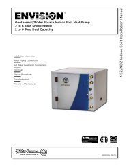
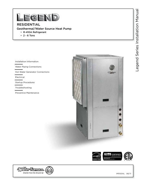
RESIDENTIAL<br />
Geothermal/Water Source Heat Pump<br />
• R-410A Refrigerant<br />
• 2 - 6 Tons<br />
<strong>Installation</strong> Information<br />
Water Piping Connections<br />
Hot Water Generator Connections<br />
<strong>Legend</strong> <strong>Series</strong> <strong>Installation</strong> <strong>Manual</strong><br />
Electrical<br />
Startup Procedures<br />
Troubleshooting<br />
Preventive Maintenance<br />
IM1100AL 06/11
LEGEND INSTALLATION MANUAL<br />
Table of Contents<br />
Model Nomenclature. .......................................................... 4<br />
General <strong>Installation</strong> Information ............................................... 5-8<br />
Water Quality ................................................................. 9<br />
Freeze Detection .............................................................. 9<br />
Condensate Drain ............................................................ 10<br />
Closed Loop Ground Source Systems ........................................... 10<br />
Open Loop Ground Water Systems ..............................................11<br />
Hot Water Generator Connections ............................................ 12-13<br />
Electrical Connections ........................................................ 14<br />
Electronic Thermostat <strong>Installation</strong> .............................................. 14<br />
Antifreeze Corrections ........................................................ 15<br />
Auxiliary Heat Ratings ........................................................ 15<br />
Electrical Data ............................................................... 16<br />
Blower Performance Data ................................................... 17-18<br />
X13 ECM Constant Torque Motors. .............................................. 19<br />
Vertical Dimensional Data .................................................. 20-22<br />
Physical Data ................................................................ 23<br />
Wiring Schematics. ........................................................ 24-27<br />
Controls. ................................................................. 28-29<br />
Unit Startup .................................................................30<br />
Troubleshooting. ............................................................. 31<br />
Startup/Troubleshooting Form ................................................. 32<br />
Operating Parameters. ........................................................ 33<br />
Operating Limits ............................................................. 33<br />
Pressure Drop. ...............................................................34<br />
Compressor and Thermistor Resistance .........................................34<br />
Refrigerant Circuit Guideline ...................................................34<br />
Heat of Extraction/Rejection. .................................................. 35<br />
Reference Calculations ........................................................ 35<br />
<strong>Legend</strong> and Notes ............................................................ 35<br />
Preventive Maintenance and Replacement Procedures. ............................ 36<br />
Service Parts. ............................................................. 37-38
LEGEND SERIES INSTALLATION MANUAL<br />
Residential<br />
Model Nomenclature<br />
1 2 3<br />
L S V<br />
4-6<br />
048<br />
7<br />
B<br />
8<br />
1<br />
9<br />
1<br />
10<br />
4<br />
11<br />
C<br />
12<br />
T<br />
13<br />
L<br />
Model Type<br />
L = <strong>Legend</strong><br />
Compressor Type<br />
S = Single Speed<br />
Cabinet Configuration<br />
V = Vertical<br />
H = Horizontal<br />
Unit Capacity<br />
Vintage<br />
A = 024-042 and 070<br />
B = 048 and 060<br />
Voltage<br />
1 = 208-230/60/1<br />
NOTE: All models include sound kits as standard equipment.<br />
Return Air Configuration<br />
L = Left<br />
R = Right<br />
Discharge Air Configuration<br />
T = Top<br />
S = Side<br />
E = End<br />
Coax Option<br />
C = Copper<br />
N = Cupronickel<br />
Fan Option<br />
0 = PSC<br />
3 = Oversized PSC (024-030, 042-048)<br />
4 = X13 ECM<br />
Hot Water Options<br />
0 = No Hot Water Generation, No IntelliStart TM<br />
1 = Hot Water Generation with factory<br />
installed pump, No IntelliStart<br />
3 = No Hot Water Generation, IntelliStart<br />
4 = Hot Water Generation with factory<br />
installed pump, IntelliStart<br />
4
LEGEND SERIES INSTALLATION MANUAL<br />
General <strong>Installation</strong> Information<br />
Safety Considerations<br />
WARNING: Before performing service or<br />
maintenance operations on a system, turn off main<br />
power switches to the indoor unit. If applicable,<br />
turn off the accessory heater power switch.<br />
Electrical shock could cause personal injury.<br />
Installing and servicing heating and air conditioning<br />
equipment can be hazardous due to system pressure and<br />
electrical components. Only trained and qualified service<br />
personnel should install, repair or service heating and air<br />
conditioning equipment. Untrained personnel can perform<br />
the basic maintenance functions of cleaning coils and<br />
cleaning and replacing filters. All other operations should<br />
be performed by trained service personnel. When working<br />
on heating and air conditioning equipment, observe<br />
precautions in the literature, tags and labels attached to the<br />
unit and other safety precautions that may apply.<br />
Follow all safety codes. Wear safety glasses and work<br />
gloves. Use a quenching cloth for brazing operations and<br />
have a fire extinguisher available.<br />
Moving and Storage<br />
Move units in the normal “up” orientation. Horizontal units<br />
may be moved and stored per the information on the<br />
packaging. Do not stack more than three units in total<br />
height. Vertical units may be stored one upon another to<br />
a maximum height of two units. Do not attempt to move<br />
units while stacked. When the equipment is received, all<br />
items should be carefully checked against the bill of lading<br />
to be sure all crates and cartons have been received.<br />
Examine units for shipping damage, removing the units<br />
from the packaging if necessary. Units in question should<br />
also be internally inspected. If any damage is noted, the<br />
carrier should make the proper notation on the delivery<br />
receipt, acknowledging the damage.<br />
Unit Location<br />
Locate the unit in an indoor area that allows for easy<br />
removal of the filter and access panels. Location should<br />
have enough space for service personnel to perform<br />
maintenance or repair. Provide sufficient room to make<br />
water, electrical and duct connection(s). If the unit is<br />
located in a confined space, such as a closet, provisions<br />
must be made for return air to freely enter the space<br />
by means of a louvered door, etc. Any access panel<br />
screws that would be difficult to remove after the unit<br />
is installed should be removed prior to setting the unit.<br />
On horizontal units, allow adequate room below the unit<br />
for a condensate drain trap and do not locate the unit<br />
above supply piping. Care should be taken when units are<br />
located in unconditioned spaces to prevent damage from<br />
frozen water lines and excessive heat that could damage<br />
electrical components.<br />
Installing Vertical Units<br />
Prior to setting the unit in place, remove and discard the<br />
compressor hold down shipping bolt located at the front of<br />
the compressor mounting bracket.<br />
Vertical units are available in left or right air return<br />
configurations. Top air discharge vertical units should be<br />
mounted level on a vibration absorbing pad slightly larger<br />
than the base to provide isolation between the unit and the<br />
floor. It is not necessary to anchor the unit to the floor.<br />
2” Extruded<br />
Polystyrene<br />
Vertical Unit Mounting<br />
5
LEGEND SERIES INSTALLATION MANUAL<br />
General <strong>Installation</strong> Information cont.<br />
Installing Horizontal Units<br />
Remove and discard the compressor hold down shipping<br />
bolt located at the front of the compressor mounting<br />
bracket prior to setting the unit in place. Horizontal units<br />
are available with side or end discharge. Horizontal units<br />
are normally suspended from a ceiling by four or six 3/8-<br />
inch diameter threaded rods. The rods are usually attached<br />
to the unit by hanger bracket kits furnished with each unit.<br />
Some residential applications require the installation of<br />
horizontal units on an attic floor. In this case, the unit<br />
should be set in a full size secondary drain pan on top of a<br />
vibration absorbing pad. The secondary drain pan prevents<br />
possible condensate overflow or water leakage damage to<br />
the ceiling. The secondary drain pan is usually placed on a<br />
plywood base isolated from the ceiling joists by additional<br />
layers of vibration absorbing material.<br />
Lay out the threaded rods per the Hanger Dimensions<br />
table. Assemble the hangers to the unit as shown on page<br />
7. Securely tighten the brackets to the unit using the weld<br />
nuts located on the underside of the bottom panel. When<br />
attaching the hanger rods to the bracket, a double nut<br />
is required since vibration could loosen a single nut. To<br />
allow filter access, one bracket on the filter side should<br />
be installed 180° from the position shown in the figure on<br />
page 7. The unit should be pitched approximately 1/4-<br />
inch towards the drain in both directions to facilitate the<br />
removal of condensate. Use only the bolts provided in the<br />
kit to attach hanger brackets. The use of longer bolts could<br />
damage internal parts.<br />
CAUTION: Do not use rods smaller than 3/8-<br />
inch diameter since they may not be strong<br />
enough to support the unit. The rods must be<br />
securely anchored to the ceiling.<br />
Horizontal Unit Mounting<br />
Flexible Duct<br />
Collar<br />
Insulate supply<br />
plenum and use<br />
O<br />
at least one 90<br />
elbow to<br />
reduce noise<br />
Threaded Rods<br />
To Line<br />
Power<br />
Hanging<br />
Brackets<br />
(Included)<br />
Hose<br />
Kits<br />
To<br />
Thermostat<br />
Electrical<br />
Disconnect<br />
Line Voltage<br />
Building Water Loop<br />
Ball Valves<br />
6
LEGEND SERIES INSTALLATION MANUAL<br />
General <strong>Installation</strong> Information cont.<br />
Unit Hanger Dimensions<br />
B<br />
B<br />
D<br />
A<br />
C<br />
A<br />
C<br />
Unit Hanger Detail<br />
LSH024 - LSH036<br />
Unit Hanger Detail<br />
LSH042 - LSH070<br />
3/8”<br />
Threaded Rod<br />
(not supplied)<br />
Vibration Isolator<br />
Washer<br />
Bolt and<br />
Lockwasher<br />
Hex Nuts<br />
(not supplied)<br />
Horizontal<br />
Unit Hanger Dimensions<br />
Models<br />
A B C D<br />
024-036<br />
in. 21.1 63.4 24.8 -<br />
cm. 53.6 161.0 63.0 -<br />
042-048<br />
in. 24.1 43.1 27.8 29.3<br />
cm. 61.2 109.5 70.6 74.4<br />
060<br />
in. 24.1 48.1 27.8 29.3<br />
cm. 61.2 122.2 70.6 74.4<br />
070<br />
in. 24.1 53.1 27.8 29.3<br />
cm. 61.2 134.9 70.6 74.4<br />
Corner Weight Locations<br />
Horizontal Corner Weights<br />
Model<br />
Post #1 Post #2 Post #3 Post #4 Total<br />
024<br />
lb 35 119 81 33 268<br />
kg [16] [54] [37] [15] [122]<br />
030<br />
lb 38 122 86 33 279<br />
kg [17] [55] [39] [15] [127]<br />
036<br />
lb 40 124 88 35 287<br />
kg [18] [56] [40] [16] [130]<br />
042<br />
lb 63 147 87 52 349<br />
kg [29] [67] [39] [24] [158]<br />
048<br />
lb 64 152 89 53 358<br />
kg [29] [69] [40] [24] [162]<br />
060<br />
lb 93 156 81 73 403<br />
kg [42] [71] [37] [33] [183]<br />
070<br />
lb 143 137 124 34 438<br />
kg [65] [62] [56] [15] [199]<br />
10/28/09<br />
Corner 3<br />
Corner 4<br />
Corner 2<br />
Corner 1<br />
7
LEGEND SERIES INSTALLATION MANUAL<br />
General <strong>Installation</strong> Information cont.<br />
Duct System<br />
An air outlet collar is provided on vertical top air discharge<br />
units and all horizontal units to facilitate a duct connection.<br />
A flexible connector is recommended for discharge<br />
and return air duct connections on metal duct systems.<br />
Uninsulated duct should be insulated with a minimum of<br />
1-inch duct insulation. Application of the unit to uninsulated<br />
ductwork in an unconditioned space is not recommended<br />
as the unit’s performance will be adversely affected.<br />
If the unit is connected to existing ductwork, check<br />
the duct system to ensure that it has the capacity to<br />
accommodate the air required for the unit application. If<br />
the duct is too small, as in the replacement of heating only<br />
systems, larger ductwork should be installed. All existing<br />
ductwork should be checked for leaks and repaired if<br />
necessary.<br />
Tighten the connectors by hand, then gently snug the<br />
fitting with pliers to provide a leak-proof joint. When<br />
connecting to an open loop (ground water) system, thread<br />
any 1-inch MPT fitting (SCH80 PVC or copper) into the<br />
swivel connector and tighten in the same manner as noted<br />
above. The open and closed loop piping system should<br />
include pressure/temperature taps for serviceability.<br />
Never use flexible hoses smaller than 1-inch inside diameter<br />
on the unit. Limit hose length to 10 feet per connection.<br />
Check carefully for water leaks.<br />
Swivel Connections<br />
The duct system should be sized to handle the design<br />
airflow quietly and efficiently. To maximize sound<br />
attenuation of the unit blower, the supply and return<br />
plenums should include an internal duct liner of fiberglass<br />
or constructed of ductboard for the first few feet. On<br />
systems employing a sheet metal duct system, canvas<br />
connectors should be used between the unit and the<br />
ductwork. If air noise or excessive airflow is a problem, the<br />
blower speed can be changed.<br />
CAUTION: Be sure to remove the shipping<br />
material from the blower discharge before<br />
connecting ductwork.<br />
Stainless<br />
Steel<br />
Snap Ring<br />
Gasket<br />
Material<br />
Locking<br />
Ring<br />
Gasket<br />
Support<br />
Sleeve<br />
Water Piping<br />
The proper water flow must be provided to each unit<br />
whenever the unit operates. To assure proper flow, use<br />
pressure/temperature ports to determine the flow rate.<br />
These ports should be located at the supply and return<br />
water connections on the unit. The proper flow rate cannot<br />
be accurately set without measuring the water pressure<br />
drop through the refrigerant-to-water heat exchanger.<br />
All source water connections on residential units are swivel<br />
piping fittings (see Swivel Connections figure) that accept<br />
a 1-inch male pipe thread (MPT). The swivel connector<br />
has a rubber gasket seal similar to a rubber hose gasket,<br />
which when mated to the flush end of any 1-inch threaded<br />
pipe provides a leak-free seal without the need for thread<br />
sealing tape or compound. Check to ensure that the rubber<br />
seal is in the swivel connector prior to attempting any<br />
connection. The rubber seals are shipped attached to the<br />
waterline. To make the connection to a ground loop system,<br />
mate the brass connector (supplied in CK4L connector<br />
kit) against the rubber gasket in the swivel connector and<br />
thread the female locking ring onto the pipe threads, while<br />
maintaining the brass connector in the desired direction.<br />
8
LEGEND SERIES INSTALLATION MANUAL<br />
Water Quality<br />
In ground water situations where scaling could be heavy<br />
or where biological growth such as iron bacteria will be<br />
present, a closed loop system is recommended. The heat<br />
exchanger coils in ground water systems may, over a period<br />
of time, lose heat exchange capabilities due to a buildup<br />
of mineral deposits inside. These can be cleaned, but only<br />
by a qualified service mechanic, as special solutions and<br />
pumping equipment are required. Hot water generator coils<br />
can likewise become scaled and possibly plugged. In areas<br />
with extremely hard water, the owner should be informed<br />
that the heat exchanger may require occasional flushing.<br />
Units with cupronickel heat exchangers are recommended<br />
for open loop applications due to the increased resistance<br />
to build-up and corrosion, along with reduced wear caused<br />
by acid cleaning. Failure to adhere to the guidelines in the<br />
water quality table could result in the loss of warranty.<br />
Material<br />
Copper<br />
90/10 Cupro-Nickel<br />
316 Stainless Steel<br />
pH Acidity/Alkalinity 7- 9<br />
7 - 9<br />
7 - 9<br />
Scaling Calcium and Magnesium Carbonate (Total Hardness) less than 350 ppm (Total Hardness) less than 350 ppm (Total Hardness) less than 350 ppm<br />
Hydrogen Sulfide<br />
Less than .5 ppm (rotten egg smell<br />
appears at 0.5 PPM)<br />
10 - 50 ppm<br />
Less than 1 ppm<br />
Sulfates<br />
Less than 125 ppm<br />
Less than 125 ppm<br />
Less than 200 ppm<br />
Chlorine<br />
Less than .5 ppm<br />
Less than .5 ppm<br />
Less than .5 ppm<br />
Chlorides<br />
Less than 20 ppm<br />
Less than125 ppm<br />
Less than 300 ppm<br />
Carbon Dioxide<br />
Less than 50 ppm<br />
10 - 50 ppm<br />
10- 50 ppm<br />
Ammonia<br />
Less than 2 ppm<br />
Less than 2 ppm<br />
Less than 20 ppm<br />
Corrosion<br />
Ammonia Chloride<br />
Less than .5 ppm<br />
Less than .5 ppm<br />
Less than .5 ppm<br />
Ammonia Nitrate<br />
Less than .5 ppm<br />
Less than .5 ppm<br />
Less than .5 ppm<br />
Ammonia Hydroxide<br />
Less than .5 ppm<br />
Less than .5 ppm<br />
Less than .5 ppm<br />
Ammonia Sulfate<br />
Less than .5 ppm<br />
Less than .5 ppm<br />
Less than .5 ppm<br />
Total Dissolved Solids (TDS)<br />
Less than 1000 ppm<br />
1000-1500 ppm<br />
1000-1500 ppm<br />
LSI Index + 0.5 to - .05<br />
+ 0.5 to - .05<br />
+ 0.5 to - .05<br />
Iron Fouling<br />
Bacterial Iron Potential<br />
< .2ppm<br />
< .2 ppm<br />
< .2 ppm<br />
(Biological Growth) Iron Oxide<br />
Less than 1 ppm. Above this level Less than 1 ppm. Above this level Less than 1 ppm. Above this level<br />
deposition will occur.<br />
deposition will occur.<br />
deposition will occur.<br />
Erosion Suspended Solids<br />
Less than 10 ppm and filtered for max of Less than 10 ppm and filtered for max of Less than 10 ppm and filtered for max of<br />
600 micron size<br />
600 micron size<br />
600 micron size<br />
Threshold Velocity (Fresh Water)<br />
< 6 ft/sec<br />
< 6 ft/sec<br />
LEGEND SERIES INSTALLATION MANUAL<br />
Condensate Drain<br />
On vertical units, the internal condensate drain assembly<br />
consists of a drain tube which is connected to the drain<br />
pan, a 3/4 in. PVC female adapter and a flexible connecting<br />
hose. The female adapter may exit either the front or the<br />
side of the cabinet. The adapter should be glued to the<br />
field-installed PVC condensate piping. On vertical units, a<br />
condensate hose is inside all cabinets as a trapping loop;<br />
therefore, an external trap is not necessary.<br />
On horizontal units, a PVC stub is provided for condensate<br />
drain piping connection. An external trap is required (see<br />
below). If a vent is necessary, an open stand pipe may be<br />
applied to a tee in the field-installed condensate piping.<br />
Horizontal Drain Connection (Composite Drain Pan)<br />
Unit Pitch for Drain<br />
3/4 in. PVC<br />
Coupling<br />
Vent (if needed)<br />
3/4 in. PVC<br />
1/2'' Pitch<br />
3/4 in. PVC tube stub<br />
1.5 in.<br />
1.5 in.<br />
1/8 in. per foot<br />
Drain<br />
Closed Loop Ground Source Systems<br />
NOTE: For closed loop systems with antifreeze protection,<br />
set SW1-2 to the “loop” position.<br />
Closed Loop Ground Source Application<br />
Once piping is completed between the unit, pumps and<br />
the ground loop, final purging and charging of the loop<br />
is required. A flush cart (or a 1.5 HP pump minimum) is<br />
needed to achieve adequate flow velocity in the loop to<br />
purge air and dirt particles from the loop itself. Antifreeze<br />
solution is used in most areas to prevent freezing. Flush<br />
the system adequately to remove as much air as possible<br />
then pressurize the loop to a static pressure of 40-50<br />
PSI (summer) or 50-75 PSI (winter). This is normally<br />
adequate for good system operation. Loop static pressure<br />
will fluctuate with the seasons. Pressures will be higher in<br />
the winter months than during the cooling season. This<br />
fluctuation is normal and should be considered when<br />
initially charging the system.<br />
Disconnects<br />
(If Applicable)<br />
Unit Supply<br />
Auxiliary Heat<br />
Supply<br />
GeoLink ®<br />
Polyethylene w/<br />
Armaflex ®<br />
Insulation<br />
Flexible Duct<br />
Collar<br />
Auxiliary<br />
Heater<br />
Knockout<br />
Unit Power<br />
Hot Water Generator<br />
Connections<br />
Drain<br />
GeoLink ®<br />
Flow<br />
Center<br />
TO<br />
LOOP<br />
After pressurization, be sure to turn the venting (burping)<br />
screw in the center of the pump two (2) turns open (water<br />
will drip out), wait until all air is purged from the pump,<br />
then tighten the plug. Ensure that the loop pumps provide<br />
adequate flow through the unit(s) by checking the pressure<br />
drop across the heat exchanger and comparing it to the unit<br />
capacity data in the specification catalog. 2.5 to 3 GPM of<br />
flow per ton of cooling capacity is recommended in earth<br />
loop applications.<br />
Low<br />
Voltage to<br />
Thermostat<br />
P/T<br />
P/T Plugs<br />
Vibration Absorbing Pad<br />
Insulated piping<br />
or hose kit<br />
NOTE: Additional information can be found in Flow<br />
Center installation manual and Flush Cart manual.<br />
10
LEGEND SERIES INSTALLATION MANUAL<br />
Open Loop Ground Water Systems<br />
Typical open loop piping is shown below. Always maintain<br />
water pressure in the heat exchanger by placing water<br />
control valves at the outlet of the unit to prevent mineral<br />
precipitation. Use a closed, bladder-type expansion tank<br />
to minimize mineral formation due to air exposure. Insure<br />
proper water flow through the unit by checking pressure<br />
drop across the heat exchanger and comparing it to the<br />
figures in unit capacity data tables in the specification<br />
catalog. 1.5-2 GPM of flow per ton of cooling capacity is<br />
recommended in open loop applications.<br />
Discharge water from the unit is not contaminated in any<br />
manner and can be disposed of in various ways, depending<br />
on local codes, i.e. recharge well, storm sewer, drain field,<br />
adjacent stream or pond, etc. Most local codes forbid<br />
the use of sanitary sewer for disposal. Consult your local<br />
building and zoning departments to assure compliance in<br />
your area.<br />
NOTE: For open loop/groundwater systems or systems that<br />
do not contain an antifreeze solution, set SW1-Switch #2 to<br />
the “WELL” position. Slow opening/closing solenoid valves<br />
(type VM) are recommended to eliminate water hammer.<br />
Open Loop Solenoid Valve Connection Option<br />
Typical quick operating external 24V water solenoid valve<br />
(type PPV100 or BPV100) wiring.<br />
Open Loop Solenoid Valve Connection Option<br />
Typical slow operating external 24V water solenoid valve<br />
(type VM) wiring and one (1) quick operating valve.<br />
SV<br />
SV<br />
Violet<br />
CC<br />
Violet<br />
CC<br />
CC<br />
Violet<br />
CC CC<br />
Violet<br />
CC<br />
VM valve<br />
VM valve<br />
Violet<br />
CC-GND<br />
Violet<br />
CC-GND<br />
CC<br />
Violet<br />
CC-GND<br />
Violet<br />
CC-GND<br />
Logic Board<br />
Logic Board<br />
Logic Board<br />
Logic Board<br />
Open System - Groundwater Application<br />
Unit Supply<br />
Aux. Heat Supply<br />
Flexible<br />
Duct Collar<br />
Rubber Bladder<br />
Expansion Tank<br />
Auxiliary<br />
Heater<br />
Knockout<br />
Hot Water Generator<br />
Connections<br />
Drain<br />
Solenoid<br />
Valve<br />
Flow Control<br />
Valve<br />
(on outlet of<br />
Solenoid Valve)<br />
Water Out<br />
Water In<br />
Disconnects<br />
(IfApplicable)<br />
Compressor<br />
Line Voltage<br />
Low Voltage<br />
to Thermostat<br />
and Valve<br />
P/T Plugs<br />
Vibration<br />
Absorbing Pad<br />
Strainer<br />
Boiler Drains<br />
For HX Flushing<br />
Shut Off Valves<br />
Shut Off Valves<br />
(to isolate solenoid<br />
valve while acid flushing)<br />
11
LEGEND SERIES INSTALLATION MANUAL<br />
Hot Water Generator Connections<br />
The heat reclaiming hot water generator coil is of vented<br />
double-wall copper construction and is suitable for potable<br />
water.<br />
To maximize the benefits of the hot water generator a<br />
minimum 50-gallon water heater is recommended. For<br />
higher demand applications, use an 80-gallon water heater<br />
or two 50-gallon water heaters connected in a series as<br />
shown below. Electric water heaters are recommended.<br />
Make sure all local electrical and plumbing codes are met<br />
for installing a hot water generator. Residential units with<br />
hot water generators contain an internal circulator and<br />
fittings. A water softener is recommended with hard water<br />
(greater than 10 grains or 170 total hardness). Once air has<br />
been purged from the water piping circuit, connect the<br />
blue wire from the hot water generator pump to T1 on the<br />
contactor (unit ships with this wire disconnected). The hot<br />
water generator pump will not operate until this wire is<br />
connected to the contactor.<br />
Water Tank Preparation<br />
To install a unit with a hot water generator, follow these<br />
installation guidelines.<br />
1. Turn off the power to the water heater.<br />
2. Attach a water hose to the water tank drain connection<br />
and run the other end of the hose to an open drain or<br />
outdoors.<br />
3. Close the cold water inlet valve to the water heater tank.<br />
4. Drain the tank by opening the valve on the bottom of<br />
the tank, then open the pressure relief valve or hot water<br />
faucet.<br />
5. Flush the tank by opening the cold water inlet valve to<br />
the water heater to free the tank of sediments. Close<br />
when draining water is clear.<br />
6. Disconnect the garden hose and remove the drain valve<br />
from the water heater.<br />
7. Refer to Plumbing <strong>Installation</strong> and Hot Water Generator<br />
Startup.<br />
CAUTION: Elements will burn out if energized dry.<br />
Typical Hot Water Generator <strong>Installation</strong><br />
Hot Water Generator <strong>Installation</strong> In Preheat Tank<br />
3/4 in. x 3/4 in. x 1/2 in. Tee<br />
Cold<br />
Water In<br />
Hot<br />
Water Out<br />
Cold<br />
Water In<br />
Hot<br />
Water Out<br />
Ball Valve<br />
Vent<br />
3/4 in. x 3/4 in. x 1/2 in. Tee<br />
Ball Valve<br />
Vent<br />
HWG<br />
Water Out<br />
P/T Relief<br />
Valve<br />
HWG<br />
Water Out<br />
P/T Relief<br />
Valve<br />
P/T Relief<br />
Valve<br />
In<br />
In<br />
HWG<br />
Water In<br />
Drain Valve<br />
HWG<br />
Water In<br />
Drain Valve Drain Valve<br />
NOTE: This configuration maximizes hot water generator<br />
capability.<br />
12
LEGEND SERIES INSTALLATION MANUAL<br />
Hot Water Generator Connections cont.<br />
Plumbing <strong>Installation</strong><br />
1. Inspect the dip tube in the water heater cold inlet<br />
for a check valve. If a check valve is present it must<br />
be removed or damage to the hot water generator<br />
circulator will occur.<br />
2. Remove drain valve and fitting.<br />
3. Thread the 3/4-inch NPT x 3-1/2-inch brass nipple into<br />
the water heater drain port.<br />
4. Attach the center port of the 3/4-inch FPT tee to the<br />
opposite end of the brass nipple.<br />
5. Attach the 1/2-inch copper to 3/4-inch NPT adaptor to<br />
the side of the tee closest to the unit.<br />
6. Install the drain valve on the tee opposite the adaptor.<br />
7. Run interconnecting tubing from the tee to DHW water<br />
out.<br />
8. Cut the cold water “IN” line going to the water heater.<br />
9. Insert the reducing solder tee in line with cold water<br />
“IN” line as shown.<br />
10. Run interconnecting copper tubing between the unit<br />
DHW water “IN” and the tee (1/2-inch nominal). The<br />
recommended maximum distance is 50 feet.<br />
11. To prevent air entrapment in the system, install a vent<br />
coupling at the highest point of the interconnecting<br />
lines.<br />
12. Insulate all exposed surfaces of both connecting water<br />
lines with 3/8-inch wall closed cell insulation.<br />
NOTE: All plumbing and piping connections must comply<br />
with local plumbing codes.<br />
Hot Water Generator Startup<br />
1. Make sure the power is off to the heat pump. Connect<br />
the blue wire from the hot water generator pump<br />
to T1 on the contactor (unit ships with this wire<br />
disconnected). The hot water generator pump will not<br />
operate until this wire is connected to the contactor.<br />
2. Close the drain valve to the water heater.<br />
3. Open the cold water supply to the tank.<br />
4. Open a hot water faucet in the building to bleed air<br />
from the system. Close when full.<br />
5. Open the pressure relief valve to bleed any remaining<br />
air from the tank, then close.<br />
6. If so equipped, turn the venting (burping) screw in the<br />
center of the pump two (2) turns open (water will drip<br />
out), wait until all air is purged from the pump, then<br />
tighten the plug. Use vent couplings to bleed air from<br />
the lines.<br />
7. Carefully inspect all plumbing for water leaks and<br />
correct as required.<br />
8. Before restoring electrical supply to the water heater,<br />
adjust the temperature setting on the tank.<br />
• On tanks with both upper and lower elements,<br />
the lower element should be turned down to<br />
the lowest setting, approximately 100°F. The<br />
upper element should be adjusted to 120°F to<br />
130°F. Depending upon the specific needs of<br />
the customer, you may want to adjust the upper<br />
element differently.<br />
• On tanks with a single element, lower the<br />
thermostat setting to 120°F.<br />
9. After the thermostat(s) is adjusted, replace the access<br />
cover and restore electrical supply to the water heater.<br />
10. Make sure that any valves in the hot water generator<br />
circuit are open.<br />
11. Turn on the unit to heating.<br />
12. The DHW pump should be running. When the pump<br />
is first started, turn the venting (burping) screw (if<br />
equipped) in the center of the pump two (2) turns open<br />
until water dribbles out, then replace. Allow the pump<br />
to run for at least five minutes to ensure that water has<br />
filled the circulator properly.<br />
13. The temperature difference between the water entering<br />
and leaving the hot water generator should be 2°F to<br />
15°F. The water flow should be approximately 0.4 GPM<br />
per ton of nominal cooling.<br />
14. Allow the unit to heat water for 15 to 20 minutes to be<br />
sure operation is normal.<br />
CAUTION: Never operate the DHW circulating<br />
pump while dry. If the unit is placed in operation<br />
before the hot water generator piping is<br />
connected, be sure that the pump wires are<br />
disconnected from the contactor.<br />
13
LEGEND SERIES INSTALLATION MANUAL<br />
Electrical Connections<br />
General<br />
Be sure the available power is the same voltage and phase<br />
as that shown on the unit serial plate. Line and low voltage<br />
wiring must be done in accordance with local codes or the<br />
National Electric Code, whichever is applicable.<br />
Unit Power Connection<br />
Connect the incoming line voltage wires to L1 and L2 of the<br />
contactor as shown below for single-phase unit. Consult<br />
the unit’s Electrical Data for correct fuse sizes.<br />
208 Volt Operation<br />
All <strong>Legend</strong> 208/230 units are factory wired for 230<br />
volt operation. For 208 volt operation, the red and blue<br />
transformer wires must be switched on terminal strip PS.<br />
Pump Wiring<br />
See Pump Wiring figure below for electrical connections<br />
from control box to pumps.<br />
Open lower front access panel. Insert power wires through<br />
knockouts on lower left side of cabinet. Route wires<br />
through left side of control box and connect to contactor<br />
and ground. Close lower front access panel before unit<br />
start-up.<br />
Line Voltage 208-230/60/1 Control Box<br />
Pump Wiring 208-230/60/1<br />
Loop Pump<br />
Power<br />
CC<br />
CC<br />
Ground<br />
Ground<br />
L2 L1<br />
PS<br />
3 1 2<br />
Line Voltage<br />
PS<br />
3 1 2<br />
Thermostat<br />
Connections<br />
TB<br />
TB<br />
Electronic Thermostat <strong>Installation</strong><br />
Position the thermostat subbase against the wall so that<br />
it is level and the thermostat wires protrude through the<br />
middle of the subbase. Mark the position of the subbase<br />
mounting holes and drill holes with a 3/16-inch bit. Install<br />
supplied anchors and secure base to the wall. Thermostat<br />
wire must be 8-conductor, 18-AWG wire. Strip the wires<br />
back 1/4-inch (longer strip lengths may cause shorts) and<br />
insert the thermostat wires into the connector as shown.<br />
Tighten the screws to insure secure connections. The<br />
thermostat has the same type connectors, requiring the<br />
same wiring. See instructions enclosed in the thermostat<br />
for detailed installation and operation information.<br />
Thermostat Wiring<br />
Thermostat<br />
R<br />
C<br />
Y1<br />
O<br />
G<br />
L<br />
W<br />
Terminal Block (TB)<br />
24VAC (Hot)<br />
R<br />
24VAC (Common)<br />
C<br />
Compressor<br />
Y1<br />
Reversing Valve<br />
O<br />
Blower Relay<br />
G<br />
System Monitor<br />
L<br />
Aux. Heat<br />
W1<br />
14
LEGEND SERIES INSTALLATION MANUAL<br />
Antifreeze Corrections<br />
Catalog performance can be corrected for antifreeze use.<br />
Please use the following table and note the example given.<br />
Antifreeze Type<br />
Antifreeze<br />
% by wt<br />
Cooling<br />
Capacity<br />
Heating<br />
Capacity<br />
Pressure Drop<br />
Antifreeze Correction Example<br />
Antifreeze solution is Propylene Glycol 20% by weight.<br />
Determine the corrected heating and cooling performance<br />
at 30°F and 90°F respectively as well as pressure drop at<br />
30°F for a <strong>Legend</strong> <strong>Series</strong> LS*024-PSC.<br />
The corrected cooling capacity at 90°F would be:<br />
24,500 MBtuh x 0.969 = 23,741 MBtuh<br />
The corrected heating capacity at 30°F would be:<br />
19,000 MBtuh x 0.913 = 17,347 MBtuh<br />
The corrected pressure drop at 30°F and 6 GPM would be:<br />
10.5 feet of head x 1.270 = 13.34 feet of head<br />
EWT - degF [DegC] 90 [32.2] 30 [-1.1] 30 [-1.1]<br />
Water 0 1.000 1.000 1.000<br />
10 0.991 0.973 1.075<br />
20 0.979 0.943 1.163<br />
Ethylene Glycol 30 0.965 0.917 1.225<br />
40 0.955 0.890 1.324<br />
50 0.943 0.865 1.419<br />
10 0.981 0.958 1.130<br />
20 0.969 0.913 1.270<br />
Propylene Glycol 30 0.950 0.854 1.433<br />
40 0.937 0.813 1.614<br />
50 0.922 0.770 1.816<br />
10 0.991 0.927 1.242<br />
20 0.972 0.887 1.343<br />
Ethanol 30 0.947 0.856 1.383<br />
40 0.930 0.815 1.523<br />
50 0.911 0.779 1.639<br />
10 0.986 0.957 1.127<br />
20 0.970 0.924 1.197<br />
Methanol 30 0.951 0.895 1.235<br />
40 0.936 0.863 1.323<br />
50 0.920 0.833 1.399<br />
Warning: Gray area represents antifreeze concentrations greater than 35% by weight and<br />
should be avoided due to the extreme performance penalty they represent.<br />
Auxiliary Heat Ratings<br />
Model<br />
KW BTU/HR Min <strong>Legend</strong> <strong>Series</strong> Compatibility<br />
208V 230V Stages 208V 230V CFM 024 - 036 042 048 - 070<br />
EAM(H)5 3.6 4.8 1 12,300 16,300 450 •<br />
EAM(H)8 5.7 7.6 1 19,400 25,900 550 •<br />
EAM(H)10 7.2 9.6 1 24,600 32,700 650 •<br />
EAL(H)10 7.2 9.6 1 24,600 32,700 1100 • •<br />
EAL(H)15 10.8 14.4 1 36,900 49,100 1250 • •<br />
EAL(H)20 14.4 19.2 1 49,200 65,500 1500 •<br />
9/18/09<br />
Model<br />
Supply<br />
Circuit<br />
Heater Amps Min Circuit Amp Max Fuse (USA) Max Fuse (CAN) Max CKT BRK<br />
208 V 240 V 208 V 240 V 208 V 240 V 208 V 240 V 208 V 240 V<br />
EAM(H)5 Single 17.3 20 26.7 30 30 30 30 30 30 30<br />
EAM(H)8 Single 27.5 31.7 39.3 44.6 40 45 40 45 40 50<br />
EAM(H)10 Single 34.7 40 48.3 55 50 60 50 60 50 60<br />
EAL(H)10 Single 34.7 40 53.3 60 60 60 60 60 60 60<br />
Single 52.0 60 75 85 80 90 80 90 70 100<br />
EAL(H)15<br />
L1/L2 34.7 40 53.3 60 60 60 60 60 60 60<br />
L3/L4 17.3 20 21.7 25 25 25 25 25 20 30<br />
Single 69.3 80 96.7 110 100 110 100 110 100 100<br />
EAL(H)20<br />
L1/L2 34.7 40 53.3 60 60 60 60 60 60 60<br />
L3/L4 34.7 40 43.3 50 45 50 45 50 40 50<br />
All heaters rated single phase 60 cycle and include unit blower load.<br />
All fuses type “D” time delay (or HACR circuit breaker in USA)<br />
Wire length based on one-way measurement with 2% voltage drop<br />
Wire size based on 60°C (*90°C) copper conductor<br />
“H” is used in part numbers for horizontal units<br />
9/18/09<br />
15
LEGEND SERIES INSTALLATION MANUAL<br />
Electrical Data<br />
<strong>Legend</strong> with PSC Motor<br />
Model<br />
Compressor<br />
Model No.<br />
Rated<br />
Voltage<br />
Voltage<br />
Min/Max<br />
HACR circuit breaker in USA only<br />
* With optional high-static PSC motor<br />
** With optional IntelliStart TM , only available on 208-230/60/1<br />
NOTE: High-static option not available on 036, 060, and 070 model sizes.<br />
Compressor<br />
MCC RLA LRA LRA**<br />
HWG<br />
Pump<br />
FLA<br />
Ext<br />
Loop<br />
FLA<br />
Blower<br />
Motor<br />
FLA<br />
024 ZP20K5E-PFV 208-230/60/1 187/253 21.0 13.5 58.3 21.0 0.4 5.4 1.2 20.5 23.9 35<br />
024* ZP20K5E-PFV 208-230/60/1 187/253 21.0 13.5 58.3 21.0 0.4 5.4 1.5 20.8 24.2 35<br />
030 ZP25K5E-PFV 208-230/60/1 187/253 22.0 14.1 73.0 26.0 0.4 5.4 1.5 21.4 24.9 35<br />
030* ZP25K5E-PFV 208-230/60/1 187/253 22.0 14.1 73.0 26.0 0.4 5.4 2.2 22.1 25.6 35<br />
036 HRH029U1LP6 208-230/60/1 187/253 27.0 17.3 96.7 34.0 0.4 5.4 2.2 25.3 29.6 45<br />
042 HRH034U1LP6 208-230/60/1 187/253 31.0 20.0 115.0 41.0 0.4 5.4 3.5 29.3 34.3 50<br />
042* HRH034U1LP6 208-230/60/1 187/253 31.0 20.0 115.0 41.0 0.4 5.4 4.6 30.4 35.4 50<br />
048 HRH040U1LP6 208-230/60/1 187/253 32.0 21.0 115.0 41.0 0.4 5.4 3.5 30.3 35.6 50<br />
048* HRH040U1LP6 208-230/60/1 187/253 32.0 21.0 115.0 41.0 0.4 5.4 4.6 31.4 36.7 50<br />
060 HRH051U1LP6 208-230/60/1 187/253 41.0 26.3 150.0 53.0 0.4 5.4 5.9 38.0 44.6 70<br />
070 HRH056U1LP6 208-230/60/1 187/253 47.0 30.1 145.0 51.0 0.4 5.4 5.9 41.8 49.3 70<br />
<strong>Legend</strong> with X13 ECM Motor<br />
Model<br />
Compressor<br />
Model No.<br />
Rated<br />
Voltage<br />
Voltage<br />
Min/Max<br />
HACR circuit breaker in USA only<br />
** With optional IntelliStart TM , only available on 208-230/60/1<br />
Compressor<br />
MCC RLA LRA LRA**<br />
HWG<br />
Pump<br />
FLA<br />
Ext<br />
Loop<br />
FLA<br />
Blower<br />
Motor<br />
FLA<br />
024 ZP20K5E-PFV 208-230/60/1 187/253 21.0 13.5 58.3 21.0 0.4 5.4 4.1 23.4 26.8 40<br />
030 ZP25K5E-PFV 208-230/60/1 187/253 22.0 14.1 73.0 26.0 0.4 5.4 4.1 24.0 27.5 40<br />
036 HRH029U1LP6 208-230/60/1 187/253 27.0 17.3 96.7 34.0 0.4 5.4 4.1 27.2 31.5 45<br />
042 HRH034U1LP6 208-230/60/1 187/253 31.0 20.0 115.0 41.0 0.4 5.4 7.6 33.4 38.4 50<br />
048 HRH040U1LP6 208-230/60/1 187/253 32.0 21.0 115.0 41.0 0.4 5.4 7.6 34.4 39.7 60<br />
060 HRH051U1LP6 208-230/60/1 187/253 41.0 26.3 150.0 53.0 0.4 5.4 7.6 39.7 46.3 70<br />
070 HRH056U1LP6 208-230/60/1 187/253 47.0 30.1 145.0 51.0 0.4 5.4 7.6 43.5 51.0 80<br />
Total<br />
Unit<br />
FLA<br />
Total<br />
Unit<br />
FLA<br />
Min<br />
Circ<br />
Amp<br />
Min<br />
Circ<br />
Amp<br />
Max<br />
Fuse/<br />
HACR<br />
1/12/10<br />
Max<br />
Fuse/<br />
HACR<br />
10/20/09<br />
16
LEGEND SERIES INSTALLATION MANUAL<br />
Blower Performance Data - PSC<br />
Standard PSC Motor<br />
Model<br />
024<br />
030<br />
036<br />
042<br />
048<br />
060<br />
070<br />
Blower Blower Motor<br />
Airflow (cfm) at External Static Pressure (in. wg)<br />
Spd Size HP 0.00 0.05 0.10 0.15 0.20 0.25 0.30 0.35 0.40 0.45 0.50 0.60 0.70 0.80 0.90 1.00<br />
H<br />
1065 1045 1030 1005 975 950 925 900 870 835 800 - - - - -<br />
M 9 x 7 1/5 880 865 850 830 815 795 775 750 725 700 670 - - - - -<br />
L 805 790 780 765 745 725 710 685 660 630 600 - - - - -<br />
H<br />
1120 1100 1070 1050 1040 1030 1020 1010 1000 980 830 - - - - -<br />
M 9 x 7 1/3 1020 1000 980 960 920 880 860 840 820 790 - - - - - -<br />
L 860 850 840 830 810 800 780 760 740 710 - - - - - -<br />
H<br />
1360 1340 1320 1290 1260 1220 1185 1130 1080 1045 1010 910 855 - - -<br />
M 9 x 7 1/2 1205 1190 1170 1145 1120 1085 1050 1015 980 940 900 845 - - - -<br />
L 1070 1060 1050 1035 1020 995 970 940 910 875 840 780 - - - -<br />
H<br />
1705 1685 1665 1645 1625 1595 1565 1530 1500 1450 1405 1260 1140 - - -<br />
M 10 x 10 1/2 1485 1475 1465 1445 1430 1410 1390 1350 1315 1260 1210 1110 1010 - - -<br />
L 1180 1165 1150 1135 1120 1090 1060 1030 1000 965 920 855 - - - -<br />
H<br />
1930 1910 1885 1860 1830 1790 1750 1710 1665 1620 1580 1280 1235 - - -<br />
M 10 x 10 1/2 1580 1565 1550 1535 1525 1505 1485 1445 1410 1310 1215 1130 1030 - - -<br />
L 1180 1170 1160 1140 1120 1100 1080 1050 1020 970 930 875 - - - -<br />
H<br />
2360 2330 2300 2270 2240 2215 2190 2160 2130 2095 2060 1985 1920 1855 - -<br />
M 11 x 10 1 2165 2130 2095 2070 2050 2030 2010 1985 1965 1930 1900 1850 1775 1700 - -<br />
L 1965 1940 1920 1900 1885 1870 1855 1825 1800 1780 1760 1720 1625 1530 - -<br />
H<br />
2450 2435 2420 2395 2370 2340 2310 2280 2250 2225 2200 2040 2000 1950 - -<br />
M 11 x 10 1 2215 2190 2170 2155 2140 2120 2095 2070 2045 2015 1990 1940 1876 1795 - -<br />
L 2005 1990 1975 1960 1950 1940 1925 1910 1890 1865 1845 1780 1710 1565 - -<br />
11/13/09<br />
Factory settings are in Bold<br />
Air flow values are with dry coil and standard filter<br />
For wet coil performance first calculate the face velocity of the air coil (Face Velocity [fpm] = Airflow [cfm] / Face Area [sq ft]).<br />
Then for velocities of 200 fpm reduce the static capability by 0.03 in. wg, 300 fpm by 0.08 in. wg, 400 fpm by 0.12 in. wg. and 500 fpm by 0.16 in. wg.<br />
Optional High Static PSC Motor<br />
Model<br />
024<br />
030<br />
042<br />
048<br />
Blower Blower Motor<br />
Airflow (cfm) at External Static Pressure (in. wg)<br />
Spd Size HP 0.00 0.05 0.10 0.15 0.20 0.25 0.30 0.35 0.40 0.45 0.50 0.60 0.70 0.80 0.90 1.00<br />
H<br />
1120 1100 1070 1050 1040 1030 1020 1010 1000 980 830 - - - - -<br />
M 9 x 7 1/3 1020 1000 980 960 920 880 860 840 820 790 - - - - - -<br />
L 860 850 840 830 810 800 780 760 740 710 - - - - - -<br />
H<br />
1340 1320 1300 1270 1240 1200 1160 1115 1070 1025 985 880 - - - -<br />
M 9 x 7 1/2 1185 1175 1165 1130 1095 1065 1035 1000 965 920 880 795 - - - -<br />
L 1050 1040 1030 1015 1000 980 960 925 895 855 815 - - - - -<br />
H<br />
2095 2080 2060 2020 1980 1950 1920 1880 1840 1780 1725 1550 1335 1120 - -<br />
M 10 x 10 3/4 1960 1940 1920 1890 1865 1830 1800 1760 1725 1670 1620 1435 1300 - - -<br />
L 1800 1780 1760 1740 1725 1695 1670 1625 1585 1525 1465 1300 1200 - - -<br />
H<br />
2095 2080 2060 2020 1980 1950 1920 1880 1840 1780 1725 1550 1335 1120 - -<br />
M 10 x 10 3/4 1960 1940 1920 1890 1865 1830 1800 1760 1725 1670 1620 1435 1300 - - -<br />
L 1800 1780 1760 1740 1725 1695 1670 1625 1585 1525 1465 1300 1200 - - -<br />
Factory settings are in Bold<br />
11/4/09<br />
Air flow values are with dry coil and standard filter<br />
For wet coil performance first calculate the face velocity of the air coil (Face Velocity [fpm] = Airflow [cfm] / Face Area [sq ft]).<br />
Then for velocities of 200 fpm reduce the static capability by 0.03 in. wg, 300 fpm by 0.08 in. wg, 400 fpm by 0.12 in. wg. and 500 fpm by 0.16 in. wg.<br />
Setting Blower Speed - PSC<br />
CAUTION: Disconnect all power before<br />
performing this operation.<br />
FAN SPEED WIRE<br />
HIGH MEDIUM LOW<br />
PSC FAN MOTOR BODY<br />
17
LEGEND SERIES INSTALLATION MANUAL<br />
Blower Performance Data - X13 ECM<br />
Model<br />
024<br />
030<br />
036<br />
042<br />
048<br />
060<br />
070<br />
Motor<br />
Spd<br />
Motor<br />
Tap<br />
High 5<br />
Blower<br />
Size<br />
Motor<br />
HP<br />
Airflow (cfm) at External Static Pressure (in. wg)<br />
0.00 0.05 0.10 0.15 0.20 0.25 0.30 0.35 0.40 0.45 0.50 0.60 0.70 0.80 0.90 1.00<br />
980 960 940 930 920 905 890 875 860 840 820 800 745 - - -<br />
Med High 4 890 878 865 845 825 813 800 785 770 753 735 710 665 - - -<br />
Med 3 9 x 7 1/2 830 815 800 788 775 755 735 723 710 690 670 640 600 - - -<br />
Med Low 2 780 760 740 703 665 653 640 620 600 585 570 - - - - -<br />
Low 1 625 593 560 535 510 495 480 455 430 410 390 - - - - -<br />
High 5<br />
1340 1310 1280 1240 1200 1170 1140 1095 1050 1015 980 900 800 - - -<br />
Med High 4 1130 1115 1100 1085 1070 1057 1044 1022 1000 970 940 870 780 - - -<br />
Med 3 9 x 7 1/2 1030 1005 980 965 950 935 920 900 880 870 860 830 750 - - -<br />
Med Low 2 960 945 930 915 900 885 870 855 840 825 810 790 740 - - -<br />
Low 1 790 765 740 725 710 690 670 660 650 630 610 580 500 - - -<br />
High 5<br />
1370 1345 1320 1285 1250 1220 1190 1158 1125 1085 1045 960 - - - -<br />
Med High 4 1265 1253 1240 1220 1200 1175 1150 1120 1090 1053 1015 - - - - -<br />
Med 3 9 x 7 1/2 1160 1143 1125 1113 1100 1085 1070 1055 1040 1020 1000 - - - - -<br />
Med Low 2 1110 1095 1080 1065 1050 1038 1025 1008 990 980 970 - - - - -<br />
Low 1 825 803 780 770 760 740 720 705 690 670 650 - - - - -<br />
High 5<br />
1840 1825 1810 1790 1770 1745 1720 1700 1680 1660 1640 1600 1570 1530 1480 -<br />
Med High 4 1730 1713 1695 1670 1645 1623 1600 1575 1550 1535 1520 1480 1440 1390 1350 -<br />
Med 3 11 x 10 1 1630 1610 1590 1563 1535 1513 1490 1470 1450 1425 1400 1370 1330 1290 - -<br />
Med Low 2 1550 1520 1490 1465 1440 1415 1390 1370 1350 1330 1310 1260 1220 1180 - -<br />
Low 1 1380 1340 1300 1275 1250 1225 1200 1175 1150 1125 1100 1030 980 820 - -<br />
High 5<br />
2060 2045 2030 2015 2000 1970 1940 1925 1910 1890 1870 1830 1800 1750 1740 -<br />
Med High 4 1880 1860 1840 1825 1810 1785 1760 1740 1720 1705 1690 1640 1610 1570 1535 -<br />
Med 3 11 x 10 1 1790 1770 1750 1730 1710 1685 1660 1640 1620 1600 1580 1550 1510 1460 - -<br />
Med Low 2 1670 1650 1630 1605 1580 1555 1530 1510 1490 1470 1450 1410 1370 1340 - -<br />
Low 1 1430 1405 1380 1353 1325 1303 1280 1255 1230 1210 1190 1130 1070 925 - -<br />
High 5<br />
2400 2360 2330 2315 2300 2290 2285 2275 2265 2250 2230 2200 2165 2110 2080 2030<br />
Med High 4 2180 2160 2140 2130 2120 2105 2090 2075 2060 2045 2030 2000 1960 1930 1890 1850<br />
Med 3 11 x 10 1 2080 2050 2020 2010 2000 1985 1970 1955 1940 1925 1910 1870 1840 1800 1760 1720<br />
Med Low 2 1930 1920 1910 1893 1875 1863 1850 1833 1815 1798 1780 1740 1700 1660 1620 1590<br />
Low 1 1750 1735 1720 1698 1675 1658 1640 1620 1600 1583 1565 1525 1490 1450 1410 1350<br />
Factory settings are in Bold<br />
11/13/09<br />
Air flow values are with dry coil and standard filter<br />
For wet coil performance first calculate the face velocity of the air coil (Face Velocity [fpm] = Airflow [cfm] / Face Area [sq ft]).<br />
Then for velocities of 200 fpm reduce the static capability by 0.03 in. wg, 300 fpm by 0.08 in. wg, 400 fpm by 0.12 in. wg. and 500 fpm by 0.16 in. wg.<br />
ISO/AHRI rating point on the LS*070 will require moving the red wire on the motor to high speed (tap 5) and disconnecting the tan wire from tap 5.<br />
18
LEGEND SERIES INSTALLATION MANUAL<br />
X13 ECM Constant Torque Motors<br />
The X13 is a ‘Constant Torque’ ECM motor and delivers air<br />
flow similar to a PSC but operates as efficiently as an ECM<br />
Variable Speed Motor. Because it’s an ECM Motor, the X13<br />
can ramp slowly up or down like the ECM Variable Speed<br />
Motor. There are 5 possible speed taps available on the X13<br />
motor with #1 being the lowest airflow and #5 being the<br />
highest airflow. These speed selections are preset at the<br />
time of manufacture and are easily changed in the field if<br />
necessary. The G, Y1 and W signals are wired to the motor<br />
at the factory. A gray wire is tied to the motor wire bundle<br />
for the Y2 signal and can be field connected to the motor if<br />
desired.<br />
X13 Benefits:<br />
- High efficiency<br />
- Soft start<br />
- 5 speeds with up to 4 speeds on-line<br />
- Built in logic allows air flow to change with G, Y1,<br />
Y2 and W signals<br />
- Super efficient low airflow continuous blower<br />
setting (G)<br />
If more than one tap are energized at the same time, built<br />
in logic gives precedence to the highest tap number and<br />
allows air flow to change with G, Y1, Y2 and W signals.<br />
Each of those 5 speeds has a specific ‘Torque’ value<br />
programmed into the motor for each speed selection. As<br />
static pressure increases, airflow decreases resulting in less<br />
torque on the rotor. The motor responds only to changes in<br />
torque and adjusts its speed accordingly.<br />
The X13 motor is powered by 208-230VAC but the motor<br />
speed is energized by 24VAC.<br />
X13 ECM Motor Connections<br />
Power Connection - 3/16 in. quick connects - Line 1 (orange<br />
wire) to L, Ground (green wire) to G, Line 2 (for 208V-230V<br />
units) to N (brown wire).<br />
Signal Connection - 1/4 in. quick connects - Common to C,<br />
24VAC to Taps #1-5.<br />
Applying 24VAC power between any of the motor taps 1-5<br />
(1/4 in. quick connects) and common will signal the motor<br />
to run and regulate torque at the programmed level. The<br />
tap input voltage must be in the range 12-33VAC. The X13<br />
will have less variation over the operating static pressure<br />
range versus a PSC motor as well as a significant watts<br />
reduction due to the high motor efficiency.<br />
Thermal protection - Motor is electronically protected.<br />
Locked Rotor Amps - If motor speed decreases below a<br />
programmed stall speed, the motor will shut down and<br />
after a delay period, the control will attempt to restart the<br />
motor.<br />
The X13 speed tap selections are as follows:<br />
The blue wire should be placed on the speed tap desired<br />
for the (G) continuous blower setting – factory wired to Tap<br />
1.<br />
The red wire should be placed on the speed tap desired<br />
during compressor operation (Y1 signal) – factory wired to<br />
Tap 3 or 4.<br />
The gray wire is not factory wired to the motor and is<br />
tied to the wire harness. It is field connected and can be<br />
used with 3ht/2cl thermostats or IntelliZone to deliver the<br />
required air flow for the Y2 signal.<br />
The tan wire should be placed on the speed tap desired for<br />
auxiliary heat (W signal) – factory wired to Tap 5.<br />
19
LEGEND SERIES INSTALLATION MANUAL<br />
Vertical Dimensional Data<br />
U<br />
R<br />
Top<br />
P<br />
S<br />
T<br />
R<br />
Top<br />
P<br />
U<br />
V<br />
Q<br />
Q<br />
V<br />
Service Access<br />
2 ft. (61 cm)<br />
Left Return<br />
Right Return<br />
Service Access<br />
2 ft. (61 cm)<br />
Y<br />
X<br />
Z<br />
Z<br />
X<br />
Y<br />
N M<br />
N<br />
M<br />
W<br />
W<br />
C<br />
C<br />
L<br />
K<br />
J<br />
E H F G<br />
L<br />
K<br />
J<br />
E H F G<br />
B<br />
Left<br />
A<br />
Front<br />
D<br />
A<br />
Front<br />
D<br />
B<br />
Right<br />
20
LEGEND SERIES INSTALLATION MANUAL<br />
Vertical Dimensional Data cont.<br />
Vertical<br />
Topflow<br />
Model<br />
A<br />
Width<br />
Overall Cabinet Water Connections Electrical Connections<br />
B<br />
Depth<br />
C<br />
Height<br />
D<br />
Loop<br />
In<br />
E<br />
Loop<br />
Out<br />
F<br />
HWG<br />
In<br />
G<br />
HWG<br />
Out<br />
H<br />
Condensate<br />
Loop<br />
Water<br />
FPT<br />
HWG<br />
FPT<br />
J K L M N<br />
Low<br />
Voltage<br />
Ext<br />
Pump<br />
Power<br />
Supply<br />
024 in. 22.3 26.3 44.4 1.9 6.9 13.5 16.4 10.2 1” 1” 5.1 10.8 16.5 5.9 3.3<br />
cm. 56.6 66.8 112.8 4.8 17.5 34.3 41.7 25.9 Swivel Swivel 13.0 27.4 41.9 15.0 8.4<br />
030 in. 22.3 26.3 44.4 1.9 6.9 13.5 16.4 10.2 1” 1” 5.1 10.8 16.5 5.9 3.3<br />
cm. 56.6 66.8 112.8 4.8 17.5 34.3 41.7 25.9 Swivel Swivel 13.0 27.4 41.9 15.0 8.4<br />
036 in. 22.3 26.3 48.4 1.9 6.9 13.5 16.4 10.2 1” 1” 5.1 10.8 16.5 5.9 3.3<br />
cm. 56.6 66.8 122.9 4.8 17.5 34.3 41.7 25.9 Swivel Swivel 13.0 27.4 41.9 15.0 8.4<br />
042 in. 25.4 31.4 50.4 2.3 7.3 15.9 18.9 10.6 1” 1” 6.5 12.2 17.9 5.9 3.3<br />
cm. 64.5 79.8 128.0 5.7 18.4 40.4 48.0 26.9 Swivel Swivel 16.5 31.0 45.5 15.0 8.4<br />
048 in. 25.4 31.4 50.4 2.3 7.3 15.9 18.9 10.6 1” 1” 6.5 12.2 17.9 5.9 3.3<br />
cm. 64.5 79.8 128.0 5.7 18.4 40.4 48.0 26.9 Swivel Swivel 16.5 31.0 45.5 15.0 8.4<br />
060 in. 25.4 31.4 54.4 2.3 7.3 15.9 18.9 10.6 1” 1” 6.5 12.2 17.9 5.9 3.3<br />
cm. 64.5 79.8 138.2 5.8 18.5 40.4 48.0 26.9 Swivel Swivel 16.5 31.0 45.5 15.0 8.4<br />
070 in. 25.4 31.4 58.4 2.3 7.3 15.9 18.9 10.6 1” 1” 6.5 12.2 17.9 5.9 3.3<br />
cm. 64.5 79.8 148.3 5.8 18.5 40.4 48.0 26.9 Swivel Swivel 16.5 31.0 45.5 15.0 8.4<br />
Vertical<br />
Topflow<br />
Model<br />
Discharge Connection<br />
duct flange installed (±0.10 in)<br />
Return Connection<br />
using std deluxe filter rack (±0.10 in)<br />
P Q R S T U V W X Y Z<br />
Supply<br />
Width<br />
Supply<br />
Depth<br />
Return<br />
Depth<br />
Return<br />
Height<br />
024<br />
in. 14.0 14.0 6.2 0.8 2.7 2.3 22.0 22.0 1.9 1.0 25.7<br />
cm. 35.6 35.6 15.7 2.0 6.9 5.8 55.9 55.9 4.8 2.5 65.3<br />
030<br />
in. 14.0 14.0 6.2 0.8 2.7 2.3 22.0 22.0 1.9 1.0 25.7<br />
cm. 35.6 35.6 15.7 2.0 6.9 5.8 55.9 55.9 4.8 2.5 65.3<br />
036<br />
in. 14.0 14.0 6.2 0.8 2.7 2.3 22.1 26.1 1.9 1.0 25.7<br />
cm. 35.6 35.6 15.7 2.0 6.9 5.8 56.1 66.3 4.8 2.5 65.3<br />
042<br />
in. 18.0 18.0 6.9 1.1 3.8 1.7 28.1 26.0 2.0 1.0 28.7<br />
cm. 45.7 45.7 17.5 2.8 9.7 4.3 71.4 66.0 5.1 2.5 72.9<br />
048<br />
in. 18.0 18.0 6.9 1.1 3.8 1.7 28.1 26.0 2.0 1.0 28.7<br />
cm. 45.7 45.7 17.5 2.8 9.7 4.3 71.4 66.0 5.1 2.5 72.9<br />
060<br />
in. 18.0 18.0 6.9 1.1 3.8 1.7 28.1 30.0 2.0 1.0 28.7<br />
cm. 45.7 45.7 17.5 2.8 9.7 4.3 71.4 76.2 5.1 2.5 72.9<br />
070<br />
in. 18.0 18.0 6.9 1.1 3.8 1.7 28.1 34.0 2.0 1.0 28.7<br />
cm. 45.7 45.7 17.5 2.8 9.7 4.3 71.4 86.4 5.1 2.5 72.9<br />
Condensate is 3/4 in. PVC female glue socket and is switchable from side to front<br />
Unit shipped with deluxe 1 in. (field adjustable to 2 in.) duct collar/filter rack extending from unit 3.25 in. and is suitable for duct connection.<br />
Discharge flange is field installed and extends 1 in. [25.4 mm] from cabinet<br />
21
LEGEND SERIES INSTALLATION MANUAL<br />
Horizontal Dimensional Data<br />
Q<br />
AA<br />
BB<br />
Z<br />
CC<br />
AA<br />
DD<br />
C<br />
W<br />
X<br />
Left Return<br />
End Discharge<br />
S<br />
Q<br />
V<br />
Y<br />
B<br />
Left Return Filter<br />
Side View<br />
DD<br />
L K<br />
J<br />
AA<br />
A<br />
Left Return<br />
Front View<br />
CC<br />
E F G<br />
D<br />
Z<br />
U<br />
Q<br />
Left Return<br />
Side Discharge View<br />
S<br />
W<br />
M N P<br />
R<br />
T<br />
V<br />
B<br />
Right Return<br />
Side Discharge View<br />
K L<br />
C<br />
J<br />
FF<br />
L K<br />
J<br />
A<br />
Right Return<br />
Front View<br />
E F G<br />
D<br />
Y<br />
Right Return Filter<br />
Side View<br />
FF<br />
H<br />
HH<br />
U<br />
T<br />
H Q<br />
Right Return<br />
End Discharge<br />
M N P<br />
EE<br />
GG<br />
EE<br />
GG<br />
Unit Hanger Detail<br />
LSH024 - LSH036<br />
Unit Hanger Detail<br />
LSH042 - LSH070<br />
Left Return<br />
End Discharge<br />
Left Return<br />
Side Discharge<br />
Right Return<br />
Side Discharge<br />
Right Return<br />
End Discharge<br />
Horizontal<br />
Models<br />
024-<br />
036<br />
042-<br />
048<br />
060<br />
070<br />
Overall Cabinet Water Connections Electrical Knockouts<br />
A B C D E F G H Loop HWG J K L M N P Q<br />
Width Depth Height*<br />
Loop Loop HWG HWG Cond- Wa te r Water Low Ext Power Low Ext Power Elec.<br />
In Out In Out ensate FPT FPT Voltage Pump Supply Voltage Pump Supply Heat<br />
in. 22.5 63.0 19.2 2.4 7.4 13.4 16.4 0.8 1” 1” 5.9 13.7 15.7 5.8 11.6 13.6 2.8<br />
cm. 57.2 160.0 48.8 6.1 18.8 34.0 41.7 2.0 Swivel Swivel 15.0 34.8 39.9 14.7 29.5 34.5 7.1<br />
in. 25.5 72.0 21.2 2.2 7.2 15.8 18.8 0.8 1” 1” 5.9 13.7 15.7 5.8 13.7 15.7 2.5<br />
cm. 64.8 182.9 53.8 5.6 18.3 40.1 47.8 2.0 Swivel Swivel 15.0 34.8 39.9 14.7 34.8 39.9 6.4<br />
in. 25.5 77.0 21.2 2.2 7.2 15.8 18.8 0.8 1” 1” 5.9 13.7 15.7 5.9 13.7 15.7 2.5<br />
cm. 64.8 195.6 53.8 5.6 18.3 40.1 47.8 2.0 Swivel Swivel 15.0 34.8 39.9 15.0 34.8 39.9 6.4<br />
in. 25.5 82.0 21.2 2.2 7.2 15.8 18.8 0.8 1” 1” 5.9 13.7 15.7 5.9 13.7 15.7 2.5<br />
cm. 64.8 208.3 53.8 5.6 18.3 40.1 47.8 2.0 Swivel Swivel 15.0 34.8 39.9 15.0 34.8 39.9 6.4<br />
Horizontal<br />
Models<br />
024-<br />
036<br />
042-<br />
048<br />
060<br />
070<br />
Discharge Connection<br />
Return Connection<br />
PVC<br />
Unit Hanger Dimensions<br />
duct flange installed (±0.10 in.)<br />
using deluxe filter rack option (±0.10 in.)<br />
Drain<br />
R S T U V W X Y Z AA BB CC DD EE FF GG HH Size<br />
Supply Supply<br />
Return Return<br />
Height Depth<br />
Height Depth<br />
in. 6.5 9.4 10.5 6.5 2.3 5.7 6.5 16.9 30.5 2.2 2.8 1.0 1.0 21.1 63.4 24.8 n/a 3/4<br />
cm. 16.5 23.9 26.7 16.5 5.8 14.5 16.5 42.9 77.5 5.6 7.1 2.5 2.5 53.6 161.0 63.0 n/a 1.9<br />
in. 4.5 13.4 13.7 4.8 2.8 6.8 7.5 18.7 35.5 2.2 2.8 1.0 1.0 24.1 43.1 27.8 29.3 3/4<br />
cm. 11.4 34.0 34.8 12.2 7.1 17.3 19.1 47.5 90.2 5.6 7.1 2.5 2.5 61.2 109.5 70.6 74.4 1.9<br />
in. 4.5 13.4 13.7 4.8 2.8 6.8 7.5 18.7 40.5 2.2 2.8 1.0 1.0 24.1 48.1 27.8 29.3 3/4<br />
cm. 11.4 34.0 34.8 12.2 7.1 17.3 19.1 47.5 102.9 5.6 7.1 2.5 2.5 61.2 122.2 70.6 74.4 1.9<br />
in. 4.5 13.4 13.7 4.8 2.8 6.8 7.5 18.7 45.5 2.2 2.8 1.0 1.0 24.1 53.1 27.8 29.3 3/4<br />
cm. 11.4 34.0 34.8 12.2 7.1 17.3 19.1 47.5 115.6 5.6 7.1 2.5 2.5 61.2 134.9 70.6 74.4 1.9<br />
Condensate 3/4 in. PVC stub extends from cabinet approximately 1.5 in. [38.1 mm].<br />
Unit is shipped with 1 in. filter. The deluxe duct collar/filter fack is field adjustable to accept a 2 in. filter. The duct collar/filter rack extends 3.2 in. from<br />
unit, and is suitable for duct connections.<br />
Discharge flange extends 1 in. [25.4 mm] from cabinet.<br />
22
LEGEND SERIES INSTALLATION MANUAL<br />
Physical Data<br />
Compressor (1 each)<br />
Model 024 030 036 042 048 060 070<br />
Single Speed Scroll<br />
Factory Charge R410a, oz [kg] Vertical 52 [1.47] 56 [1.58] 60 [1.70] 74 [2.09] 84 [2.38] 100 [2.83] 104 [2.94]<br />
Factory Charge R410a, oz [kg] Horizontal 52 [1.47] 56 [1.58] 60 [1.70] 74 [2.09] 84 [2.38] 100 [2.83] 104 [2.94]<br />
Blower Motor & Blower<br />
Blower Motor Type/Speeds<br />
Blower Motor - hp [W]<br />
Optional - Oversized Blower Motor - hp [W]<br />
Blower Wheel Size (Dia x W), in. [mm]<br />
Coax and Water Piping<br />
X13<br />
PSC<br />
X13 ECM - 5 Speeds<br />
PSC - 3 Speeds<br />
X13 1/2 [373] 1/2 [373] 1/2 [373] 1 [746] 1 [746] 1 [746] 1 [746]<br />
PSC 1/5 [149] 1/3 [249] 1/2 [373] 1/2 [373] 1/2 [373] 1 [746] 1 [746]<br />
X13<br />
Not Available<br />
PSC 1/3 [249] 1/2 [373] Not Available 3/4 [560] 3/4 [560] Not Available Not Available<br />
X13<br />
PSC<br />
9 x 7<br />
[229 x 178]<br />
9 x 7<br />
[229 x 178]<br />
9 x 7<br />
[229 x 178]<br />
9 x 7<br />
[229 x 178]<br />
9 x 7<br />
[229 x 178]<br />
9 x 7<br />
[229 x 178]<br />
11 x 10<br />
[279 x 254]<br />
10 x 10<br />
[254 x 254]<br />
11 x 10<br />
[279 x 254]<br />
10 x 10<br />
[254 x 254]<br />
11 x 10<br />
[279 x 254]<br />
11 x 10<br />
[279 x 254]<br />
11 x 10<br />
[279 x 254]<br />
11 x 10<br />
[279 x 254]<br />
Water Connections Size - Swivel - in [mm] 1" [25.4] 1" [25.4] 1" [25.4] 1" [25.4] 1" [25.4] 1" [25.4] 1" [25.4]<br />
HWG Connection Size - Female Sweat (I.D.) - in [mm] 1/2" [12.7] 1/2" [12.7] 1/2" [12.7] 1/2" [12.7] 1/2" [12.7] 1/2" [12.7] 1/2" [12.7]<br />
Coax & Piping Water Volume - gal [l] .4 [1.4] 0.7 [2.6] .7 [2.6] .7 [2.7] 1.0 [3.8] 1.3 [4.9] 1.6 [6.1]<br />
Vertical<br />
Air Coil Dimensions (H x W), in. [mm]<br />
24 x 20<br />
[610 x 542]<br />
24 x 20<br />
[610 x 542]<br />
28 x 20<br />
[711 x 542]<br />
28 x 25<br />
[711 x 635]<br />
28 x 25<br />
[711 x 635]<br />
32 x 25<br />
[813 x 635]<br />
36 x 25<br />
[914 x 635]<br />
Air Coil Total Face Area, ft2 [m2] 3.3 [0.310] 3.3 [0.310] 3.9 [0.362] 4.9 [0.451] 4.9 [0.451] 5.6 [0.516] 6.3 [0.581]<br />
Air Coil Tube Size, in [mm] 3/8 [9.5] 3/8 [9.5] 3/8 [9.5] 3/8 [9.5] 3/8 [9.5] 3/8 [9.5] 3/8 [9.5]<br />
Air Coil Number of rows 3 3 3 3 3 3 3<br />
Filter Standard - 1" [24mm] Pleated MERV8<br />
Throwaway, in [mm]<br />
24 x 24<br />
[610 x 610]<br />
24 x 24<br />
[610 x 610]<br />
28 x 24<br />
[712 x 610]<br />
28 x 30<br />
[711 x 762]<br />
28 x 30<br />
[711 x 762]<br />
32 x 30<br />
[813 x 762]<br />
36 x 30<br />
[914 x 762]<br />
Weight - Operating, lb [kg] 258 [117] 273 [124] 308 [140] 333 [151] 360 [163] 421 [191] 435 [197]<br />
Weight - Packaged, lb [kg] 278 [126] 293 [133] 328 [149] 353 [160] 380 [172] 441 [200] 455 [206]<br />
Horizontal<br />
Air Coil Dimensions (H x W), in. [mm]<br />
18 x 27<br />
[457 x 686]<br />
18 x 27<br />
[457 x 686]<br />
18 x 30<br />
[457 x 762]<br />
20 x 35<br />
[508 x 889]<br />
20 x 35<br />
[508 x 889]<br />
20 x 40<br />
[508 x 1016]<br />
20 x 45<br />
[508 x 1143]<br />
Air Coil Total Face Area, ft2 [m2] 3.4 [0.316] 3.4 [0.316] 3.9 [0.362] 4.9 [0.451] 4.9 [0.451] 5.6 [0.516] 6.3 [0.581]<br />
Air Coil Tube Size, in [mm] 3/8 [9.5] 3/8 [9.5] 3/8 [9.5] 3/8 [9.5] 3/8 [9.5] 3/8 [9.5] 3/8 [9.5]<br />
Air Coil Number of rows 3 3 3 3 3 3 3<br />
Filter Standard - 1" [25mm] Pleated MERV8<br />
Throwaway, in [mm]<br />
1 - 18 x 32 [457<br />
x 813]<br />
1 - 18 x 32 [457<br />
x 813]<br />
1 - 18 x 32 [457<br />
x 813]<br />
1 - 20 x 37<br />
[686 x 940]<br />
1 - 20 x 37<br />
[686 x 940]<br />
1 - 20 x 20<br />
[508 x 508]<br />
1 - 20 x 22<br />
[508 x 559]<br />
1 - 20 x 25<br />
[508 x 635]<br />
1 - 20 x 22<br />
[508 x 559]<br />
Weight - Operating, lb [kg] 268 [122] 279 [127] 287 [130] 349 [158] 358 [162] 403 [183] 438 [199]<br />
Weight - Packaged, lb [kg] 288 [131] 299 [136] 307 [139] 379 [172] 388 [176] 448 [203] 483 [219]<br />
3/18/11<br />
23
LEGEND SERIES INSTALLATION MANUAL<br />
Wiring Schematics<br />
208-230/60/1 PSC<br />
Grn<br />
PSC<br />
Blower<br />
Motor<br />
Brn Wht<br />
Compressor<br />
Cap<br />
S<br />
Blue<br />
Red<br />
R<br />
C<br />
Black<br />
Auxiliary<br />
Circuit 2<br />
G L2<br />
P3<br />
H M L<br />
Cap<br />
3 Airflow<br />
Settings<br />
Tan<br />
T2<br />
L2<br />
T1<br />
CC<br />
L1<br />
NOTE 3<br />
NOTE 5<br />
Grn<br />
NOTE 4<br />
P9<br />
1<br />
2<br />
3<br />
Black<br />
RB<br />
2 4<br />
5<br />
Unit Power Supply<br />
208-230/60/1<br />
G<br />
White<br />
Black<br />
Black/White<br />
Gray/White<br />
NOTE 1<br />
2<br />
1<br />
3<br />
PS<br />
Blue<br />
230V<br />
2<br />
1<br />
3<br />
PS<br />
Brown<br />
Orange<br />
5<br />
4<br />
Pink<br />
Yel<br />
Brn<br />
Or<br />
Blk<br />
Ext Pump<br />
1/2 hp Total<br />
208-230/60/1<br />
Pump<br />
G<br />
Pump<br />
PB1<br />
2<br />
2<br />
1<br />
1<br />
CB1<br />
5<br />
A<br />
M<br />
P<br />
Orange<br />
T1<br />
L1<br />
T2<br />
CB2<br />
5<br />
A<br />
M<br />
L2 P<br />
Black<br />
Brown<br />
Black<br />
Drain<br />
Water Flow<br />
High Press.<br />
Low Press.<br />
R<br />
R<br />
R<br />
R<br />
Yellow<br />
Air Flow/Fan R<br />
Status G<br />
HW Limit Y<br />
HW<br />
R<br />
OFF<br />
SW2<br />
ON<br />
R<br />
Red<br />
208V<br />
Transformer<br />
Black/White<br />
CC<br />
Violet<br />
Violet<br />
Green<br />
Black<br />
Black<br />
Black<br />
Black<br />
R<br />
CC<br />
CCG<br />
C<br />
C<br />
R<br />
R<br />
P3<br />
P1<br />
Fan<br />
RB<br />
Gray/White Black/White<br />
Fan COM<br />
SW1 On<br />
Test<br />
Normal<br />
Loop<br />
Well<br />
Comm. T-Stat<br />
Normal<br />
Inputs /Outputs<br />
Status<br />
Split Mode<br />
Normal<br />
Yellow<br />
R<br />
C<br />
Y<br />
O<br />
P2<br />
1-HP<br />
6-HP<br />
2-LP<br />
7-LP<br />
3<br />
8-CO<br />
4-RV<br />
9-RV<br />
5-FP<br />
10-FP<br />
G/Y2<br />
LO<br />
ES<br />
NS<br />
LS<br />
HP<br />
Black<br />
Black<br />
LP<br />
Blue<br />
Blue<br />
CO<br />
Brown<br />
Orange RV<br />
Orange<br />
Yellow<br />
T<br />
Yellow<br />
NOTE 2<br />
FD<br />
C<br />
Y1<br />
W1<br />
W2<br />
TB<br />
NOTE 5<br />
Black<br />
White<br />
P1<br />
C<br />
1<br />
2<br />
3<br />
4<br />
P2<br />
P10 C 1 2 3<br />
Operational Logic Table<br />
Mode Inputs Fan Comp RV<br />
Htg Y Auto ON OFF<br />
Clg Y, O Auto ON ON<br />
Fan Only G/Y2 ON OFF OFF<br />
C<br />
C<br />
Red<br />
O<br />
O<br />
White<br />
L<br />
G<br />
Y1<br />
W<br />
Thermostat<br />
L<br />
S<br />
G<br />
X1<br />
X2<br />
Y1<br />
Orange<br />
Violet<br />
Brown<br />
Gray/Whte<br />
Black/White<br />
Blue<br />
PSC Blower Motor Factory Settings<br />
Model Vertical Horizontal<br />
024 Med Med<br />
030 Med Med<br />
036 High High<br />
042 Med Med<br />
048 High High<br />
060 Med Med<br />
070 High High<br />
W1<br />
W2<br />
TB<br />
24
1<br />
2<br />
3<br />
LEGEND SERIES INSTALLATION MANUAL<br />
Wiring Schematics cont.<br />
208-230/60/1 PSC cont.<br />
2<br />
1<br />
3<br />
PS<br />
NOTE 5<br />
Brown<br />
Grn<br />
Orange<br />
Auxiliary Electric Heat Power 208-230/60/1<br />
Circuit 2 Circuit 1<br />
G L2 L1 L2 L1 G<br />
With optional Field Installed ' EA'<br />
<strong>Series</strong> Auxiliary Electric Heat<br />
Typical schematic shown<br />
NOTE 4<br />
P9<br />
1<br />
2<br />
3<br />
5<br />
Brn<br />
4<br />
Or<br />
P8<br />
Pink 4<br />
Pink<br />
Yel 3<br />
Yel<br />
Blk 2<br />
Blk<br />
Gray 1<br />
Gray<br />
PB2<br />
Normal Mode Control Timing Table<br />
Event Normal Mode Test Mode<br />
Power On Delay<br />
5 minutes 15 seconds<br />
Compressor On Delay<br />
10 seconds 2 seconds<br />
Compressor Minimum On Time<br />
2 minutes 5 seconds<br />
Compressor Short Cycle Delay<br />
5 minutes 15 seconds<br />
Blower Off Delay<br />
30 seconds 5 seconds<br />
Fault Recognition Delay – High Pressure Less than 1 second Less than 1 second<br />
Start-Up Bypass – Low Pressure<br />
2 minutes<br />
0 seconds<br />
Fault Recognition Delay – Low Pressure<br />
30 seconds 30 seconds<br />
Start-Up Bypass – Freeze Detection Limit<br />
Fault Recognition Delay – Freeze Detection Limit<br />
Fault Recognition Delay – Condensate Overflow<br />
2 minutes<br />
30 seconds<br />
30 seconds<br />
0 seconds<br />
30 seconds<br />
30 seconds<br />
Black<br />
HP<br />
C<br />
Y1<br />
W1<br />
W2<br />
P1<br />
C<br />
1<br />
2<br />
3<br />
4<br />
Pink<br />
Yel<br />
Blk<br />
Gray<br />
ER1<br />
NO<br />
ER2<br />
NO<br />
ER3<br />
NO<br />
Blk<br />
Yel<br />
Gray<br />
P7<br />
1<br />
2<br />
3<br />
4<br />
Gray<br />
Blk<br />
Yel<br />
Pink<br />
HE1<br />
HE2<br />
HE3<br />
Gray<br />
Blk<br />
Yel<br />
Pink<br />
TS1<br />
TS2<br />
TS3<br />
DIP Switch<br />
Number<br />
Factory Setup DIP Switches (SW1)<br />
Description<br />
“OFF”<br />
Position<br />
Service Test Mode<br />
SW1- 1<br />
On the control, allows field selection of "NORMAL" or "TEST" operational modes, Test<br />
mode accelerates most timing functions 16 times to allow faster troubleshooting. Test<br />
mode also allows viewing the "CURRENT" status of the fault inputs on the LED display.<br />
Test Mode<br />
SW1- 2<br />
Freeze Detection Setting<br />
This DIP switch allows field selection of low source water thermistor fault sensing for<br />
"WELL" water (30°F) or "LOOP" (15°F) for antifreeze protected earth loops.<br />
“LOOP”<br />
(15°F)<br />
“ON” Position<br />
Normal Speed<br />
Operation<br />
“WELL”<br />
(30°F)<br />
SW1- 3 Not Available<br />
N/A Normal Operation<br />
I/O Display Mode<br />
SW1- 4 This DIP switch enables Input/Output Display or Status/Current Fault on LED Board .<br />
Input /Output Status /Current<br />
Refer to SW2 for operation and positioning.<br />
Display Mode Fault Display Mode<br />
SW1- 5 Not Available<br />
N/A Normal Operation<br />
LED Display (On LED Board)<br />
Current Fault or<br />
This DIP switch enables Normal Status or Input display mode in the "OFF" position and<br />
Status or Inputs<br />
SW2<br />
Output Display<br />
Current Fault or Output display mode in the "ON" position.<br />
Display Mode<br />
Mode<br />
Black<br />
Blue<br />
LP<br />
TB<br />
ER4<br />
Pink<br />
HE4<br />
TS4<br />
Blue<br />
CO<br />
Brown<br />
Orange RV<br />
Orange<br />
Yellow<br />
T<br />
Yellow<br />
NOTE 2<br />
FD<br />
NOTE 5<br />
Black<br />
White<br />
Operational Logic Table<br />
Mode Inputs Fan Comp RV<br />
Htg Y Auto ON OFF<br />
Clg Y, O Auto ON ON<br />
Fan Only G/Y2 ON OFF OFF<br />
P2<br />
P10 C 1 2 3 4<br />
1<br />
EA <strong>Series</strong> PCB<br />
NO<br />
DHW<br />
Pump<br />
Optional Internal<br />
Hot Water Generation Pump<br />
Hot Water<br />
Limit Switch<br />
Blue<br />
Blue<br />
T2<br />
NOTE 6<br />
T1<br />
CC<br />
LED Display Mode Table<br />
Status Display Mode<br />
LED SW1-4 On , SW2 Off<br />
Drain<br />
Water Flow<br />
Drain Pan Overflow Lockout<br />
Freeze Detection (Loop
LEGEND SERIES INSTALLATION MANUAL<br />
Wiring Schematics cont.<br />
208-230/60/1 X13 ECM<br />
Ext Pump<br />
1/2 hp Total<br />
208-230/60/1<br />
Pump<br />
G<br />
X13<br />
Blower<br />
Motor<br />
Pump<br />
L N G<br />
PB1<br />
2<br />
2<br />
1<br />
1<br />
Green<br />
Orange<br />
T1<br />
CB1<br />
5<br />
A<br />
M<br />
P L1<br />
T2<br />
L2<br />
Unit<br />
Power Supply<br />
208- 230/60/1<br />
Brown<br />
Orange<br />
Brown<br />
Black<br />
CB2<br />
5<br />
A<br />
M<br />
P<br />
G<br />
Black<br />
Cap<br />
Blue<br />
Tan<br />
Compressor<br />
S<br />
C<br />
R<br />
Red<br />
Black<br />
T2<br />
T1<br />
NOTE 3<br />
CC<br />
L2<br />
L1<br />
Black/White<br />
Gray/White<br />
2<br />
1<br />
3<br />
PS<br />
NOTE 1<br />
Black<br />
Blue<br />
230V<br />
2<br />
1<br />
3<br />
PS<br />
NOTE 7<br />
Brown<br />
NOTE 4<br />
P9<br />
1<br />
Grn<br />
2<br />
3<br />
5<br />
Orange 4<br />
A<br />
C<br />
G<br />
C 1 2 3 4 5<br />
Red<br />
208V<br />
Pink<br />
NOTE 5<br />
Transformer<br />
24V<br />
C<br />
P1<br />
Red<br />
Blue<br />
Black<br />
Yellow<br />
Black/White<br />
Y1<br />
W1<br />
W2<br />
C<br />
1<br />
2<br />
3<br />
4<br />
TB<br />
NOTE 7<br />
Tan<br />
Gray<br />
NOTE 6<br />
Drain R<br />
Water Flow R<br />
High Press. R<br />
Low Press. R<br />
Air Flow/Fan R<br />
Status G<br />
HW Limit Y<br />
HW<br />
R<br />
OFF<br />
SW2<br />
ON<br />
CC<br />
Green<br />
Violet<br />
Violet<br />
CC<br />
CCG<br />
C<br />
C<br />
R<br />
R<br />
P3<br />
P1<br />
Fan<br />
Fan COM<br />
SW1 On<br />
Test<br />
Normal<br />
Loop<br />
Well<br />
Comm. T-Stat<br />
Normal<br />
Inputs/Outputs<br />
Status<br />
Split Mode<br />
Normal<br />
Black<br />
Black<br />
Black<br />
Yellow<br />
Red<br />
Blue<br />
White<br />
Brown<br />
R<br />
C<br />
Y<br />
O<br />
Orange<br />
P2<br />
1-HP<br />
6-HP<br />
2-LP<br />
7-LP<br />
3<br />
8-CO<br />
4-RV<br />
9-RV<br />
5-FP<br />
10-FP<br />
G/Y2<br />
LO<br />
ES<br />
NS<br />
LS<br />
Violet<br />
Black<br />
Black<br />
Blue<br />
Blue<br />
Brown<br />
Orange<br />
Orange<br />
Yellow<br />
Yellow<br />
Black/White<br />
Gray/White<br />
NOTE 2<br />
HP<br />
LP<br />
CO<br />
RV<br />
T<br />
FD<br />
DHW<br />
Pump<br />
Black<br />
White<br />
P10<br />
Optional Internal<br />
Hot Water Generation Pump<br />
Hot Water<br />
Limit Switch<br />
Blue<br />
Blue<br />
T2<br />
L2<br />
C 1<br />
CC<br />
TB<br />
R<br />
R<br />
C Y1 O G L S Y2 X1 X2 W1<br />
C Y1 O G L W<br />
Thermostat<br />
Gray<br />
Y2<br />
Tan<br />
X13 MOTOR BLOWER TABLE<br />
TAP-1 TAP-2 TAP-3 T<br />
MODEL ESP Low Med. Low Medium Me<br />
(cfm) (cfm) (cfm) (<br />
024 0.3 480 670 740<br />
030 0.3 680 870 920 1<br />
036 0.3 720 1020 1070 1<br />
042 0.5 1100 1310 1410 1<br />
048 0.5 1190 1450 1580 1<br />
060 0.5 1540 1750 1880 2<br />
070 0.5 1560 1790 1900 2<br />
26
1<br />
2<br />
3<br />
LEGEND SERIES INSTALLATION MANUAL<br />
Wiring Schematics cont.<br />
208-230/60/1 X13 ECM cont.<br />
lack<br />
mer<br />
Red<br />
208V<br />
24V<br />
Blue<br />
230V<br />
Black/White<br />
2<br />
1<br />
3<br />
PS<br />
C<br />
Y1<br />
W1<br />
W2<br />
TB<br />
NOTE 7<br />
NOTE 7<br />
Brown<br />
NOTE 4<br />
P9<br />
1<br />
Grn<br />
2<br />
3<br />
5<br />
Orange 4<br />
P1<br />
C<br />
1<br />
2<br />
3<br />
4<br />
P10<br />
Auxiliary Electric Heat Power 208-230/60/1<br />
Circuit 2 Circuit 1<br />
G<br />
Brn<br />
Or<br />
Pink Blk<br />
Yel Gray<br />
C 1<br />
P2<br />
L2 L1 L2 L1<br />
2 3 4<br />
1<br />
PB2<br />
ER1<br />
NO<br />
ER2<br />
NO<br />
ER3<br />
NO<br />
ER4<br />
EA <strong>Series</strong> PCB<br />
NO<br />
G<br />
Pink<br />
Yel<br />
Blk<br />
Gray<br />
Blk<br />
Yel<br />
Gray<br />
Pink<br />
P8<br />
4<br />
3<br />
2<br />
1<br />
Pink<br />
Yel<br />
Blk<br />
Gray<br />
Gray<br />
P7<br />
1<br />
2 Blk<br />
3 Yel<br />
4<br />
Pink<br />
With optional Field Installed ' EA'<br />
<strong>Series</strong> Auxiliary Electric Heat<br />
Typical schematic shown<br />
HE1<br />
HE2<br />
HE3<br />
HE4<br />
Gray<br />
Blk<br />
Yel<br />
Pink<br />
TS1<br />
TS2<br />
TS3<br />
TS4<br />
DIP Switch<br />
Number<br />
X13 MOTOR LOW VOLTAGE CONNECTIONS<br />
Model<br />
TAP-1 TAP-2 TAP-3 TAP-4 TAP-5<br />
Low Med.Low Medium Med. Hi High<br />
024 BLUE RED TAN<br />
030 BLUE RED TAN<br />
036 BLUE RED TAN<br />
042 BLUE RED TAN<br />
048 BLUE RED TAN<br />
060 BLUE RED TAN<br />
070 BLUE RED TAN<br />
WIRE<br />
COLOR<br />
BLUE<br />
RED<br />
GRAY<br />
TAN<br />
CALL<br />
G<br />
Y1<br />
Y2<br />
W<br />
Factory Setup DIP Switches (SW1)<br />
Description<br />
Notes:<br />
DESCRIPTION<br />
FAN<br />
1ST STAGE H/C<br />
2ND STAGE H/C<br />
AUXILIARY HEAT<br />
“OFF”<br />
Position<br />
Service Test Mode<br />
SW1 - 1<br />
On the control, allows field selection of "NORMAL" or "TEST" operational modes, Test<br />
mode accelerates most timing functions 16 times to allow faster troubleshooting. Test<br />
mode also allows viewing the "CURRENT" status of the fault inputs on the LED display .<br />
Test Mode<br />
SW1 - 2<br />
Freeze Detection Setting<br />
“LOOP”<br />
This DIP switch allows field selection of low source water thermistor fault sensing for<br />
(15°F)<br />
"WELL" water (30°F) or "LOOP" (15°F)for antifreeze protected earth loops .<br />
SW1 - 3 Not Available<br />
N/A Normal Operation<br />
I /O Display Mode<br />
Input/Output Status/Current<br />
SW1 - 4 This DIP switch enables Input/Output Display or Status/Current Fault on LED Board.<br />
Display Mode Fault Display Mode<br />
Refer to SW2 for operation and positioning.<br />
SW1 - 5 Not Available<br />
N/A Normal Operation<br />
SW2<br />
LED Display (On LED Board)<br />
Status or Inputs<br />
This DIP switch enables Normal Status or Input display mode in the "OFF" position and<br />
Display Mode<br />
Current Fault or Output display mode in the "ON" position.<br />
“ON” Position<br />
Normal Speed<br />
Operation<br />
“WELL”<br />
(30°F)<br />
Current Fault or<br />
Output Display<br />
Mode<br />
Operational Logic Table<br />
Mode Inputs Fan Comp RV<br />
Htg Y Auto ON OFF<br />
Clg Y, O Auto ON ON<br />
Fan Only G/Y2 ON OFF OFF<br />
D<br />
DHW<br />
Pump<br />
Black<br />
White<br />
Optional Internal<br />
Hot Water Generation Pump<br />
Hot Water<br />
Limit Switch<br />
Blue<br />
Blue<br />
T2<br />
NOTE 8<br />
T1<br />
CC<br />
Normal Mode Control Timing Table<br />
Event Normal Mode Test Mode<br />
Power On Delay<br />
5 minutes 15 seconds<br />
Compressor On Delay<br />
10 seconds 2 seconds<br />
Compressor Minimum On Time<br />
2 minutes 5 seconds<br />
Compressor Short Cycle Delay<br />
5 minutes 15 seconds<br />
Blower Off Delay<br />
30 seconds 5 seconds<br />
Fault Recognition Delay – High Pressure<br />
Start-Up Bypass – Low Pressure<br />
Less than 1 second<br />
2 minutes<br />
Less than 1 second<br />
0 seconds<br />
Fault Recognition Delay – Low Pressure<br />
30 seconds 30 seconds<br />
Start-Up Bypass – Low Water Coil Limit<br />
Fault Recognition Delay – Low Water Coil Limit<br />
Fault Recognition Delay – Condensate Overflow<br />
2 minutes<br />
30 seconds<br />
30 seconds<br />
0 seconds<br />
30 seconds<br />
30 seconds<br />
1 - Swap blue and red leads for 208V operation<br />
2 - Requires common connection or 24 VAC for activation<br />
3 - Wires are removed when Auxiliary Heat is installed.<br />
4 - Field supplied Square D part number QOU141100JBAF<br />
(jumper bar assembly) should be used for single source power.<br />
5 - Refer to the X13 Motor Low Voltage Connection Table.<br />
6 - Wire is provided with the unit but not connected to the<br />
X13 motor.<br />
7 - Wires are provided with the unit but not connected.<br />
8 - Wire not connected at factory, connect to T1 for HW<br />
pump operation.<br />
<strong>Legend</strong><br />
X13 MOTOR BLOWER TABLE<br />
TAP-1 TAP-2 TAP-3 TAP-4 TAP-5<br />
MODEL ESP Low Med. Low Medium Med. Hi High<br />
(cfm) (cfm) (cfm) (cfm) (cfm)<br />
024 0.3 480 670 740 800 890<br />
030 0.3 680 870 920 1040 1140<br />
036 0.3 720 1020 1070 1150 1190<br />
042 0.5 1100 1310 1410 1520 1640<br />
048 0.5 1190 1450 1580 1690 1870<br />
060 0.5 1540 1750 1880 2010 2210<br />
070 0.5 1560 1790 1900 2030 2230<br />
L2<br />
L1<br />
LED Display Mode Table<br />
Status Display Mode<br />
LED SW1-4 On, SW2 Off<br />
Drain<br />
Water Flow<br />
High Press.<br />
Low Press.<br />
Air Flow<br />
Status<br />
Drain Pan Overflow Lockout<br />
Freeze Detection (Loop
LEGEND SERIES INSTALLATION MANUAL<br />
Controls<br />
Standard Microprocessor<br />
charge damage, and a low suction temperature thermistor<br />
for freeze sensing. Upon a continuous 30-second<br />
measurement of the fault (immediate for high pressure),<br />
compressor operation is suspended, the appropriate<br />
lockout LED begins flashing. (Refer to the “Fault Retry”<br />
section below).<br />
Testing<br />
The control allows service personnel to shorten most timing<br />
delays for faster diagnostics.<br />
Flexible Control Options<br />
The standard control system is a microprocessor-based<br />
printed circuit board, (PCB), conveniently located in the unit<br />
control box for accessibility. The microprocessor control<br />
is specifically designed for geothermal water source heat<br />
pumps to integrate compressors and advanced features<br />
needed in geothermal water source heat pump applications.<br />
The microprocessor provides control of the entire unit as<br />
well as outputs for status modes, faults, and diagnostics.<br />
Low voltage thermostat terminal strips provide convenient<br />
field connections. LEDs are located in the corner post to<br />
assist the technician when servicing the unit.<br />
Startup<br />
The unit will not operate until all the inputs and safety<br />
controls are checked for normal conditions. At first<br />
powerup, a five minute delay is employed before the<br />
compressor is energized.<br />
Component Sequencing Delays<br />
Components are sequenced and delayed for optimum<br />
space conditioning performance.<br />
Short Cycle Protection<br />
The control allows a minimum on time of 2 minutes and a<br />
minimum off time of 5 minutes for short cycle protection.<br />
Condensate Overflow Protection<br />
The control board incorporates an impedance<br />
sensing liquid sensor at the top of the drain pan. Upon<br />
a continuous 30-second sensing of the condensate,<br />
compressor operation is suspended (see Fault Retry), and<br />
the condensate overflow lockout LED begins flashing.<br />
Safety Controls<br />
The control receives separate signals for a high pressure<br />
switch for safety, a low pressure switch to prevent loss of<br />
Fault Retry<br />
All faults are retried twice before finally locking the unit out.<br />
An output signal is made available for a fault LED at the<br />
thermostat. The “Fault Retry” feature is designed to prevent<br />
nuisance service calls.<br />
Diagnostics<br />
The control board allows all inputs and outputs to be<br />
displayed on the LEDs for fast and simple control board<br />
diagnosis.<br />
Emergency Shutdown<br />
A grounded signal to common or connecting 24 VAC to<br />
the ES terminal places the controller into the emergency<br />
shutdown mode. The compressor and blower operation are<br />
suspended while in the emergency shutdown mode.<br />
Heating Operation<br />
Heating (Y1)<br />
The blower motor is started immediately after the “Y1” input<br />
is received, and the compressor is energized 10 seconds<br />
after the “Y1” input.<br />
Heat, 2 nd Stage (Y1, Y2) X13 ECM<br />
When the gray wire is connected to the motor (Y2 is field<br />
connected) the blower speed will increase.<br />
Heat, 3 rd Stage (Y1, Y2, W) X13 ECM<br />
When a "W" input is received the blower speed will increase<br />
and all stages of resistance heat will be energized along<br />
with the compressor operation.<br />
Emergency Heat (W only)<br />
The blower is started on high speed and all stages of<br />
resistance heat are energized.<br />
Cooling Operation<br />
In all cooling operations, the reversing valve directly tracks<br />
the “O” input. Thus, anytime the “O” input is present, the<br />
reversing valve will be energized.<br />
28
LEGEND SERIES INSTALLATION MANUAL<br />
Controls cont.<br />
Cooling (Y1,O)<br />
The blower motor is started immediately after the “Y1” input<br />
is received, and the compressor is energized 10 seconds<br />
after the “Y1” input.<br />
Cool, 2 nd Stage (Y1, Y2, 0)<br />
When the gray wire is connected to the motor (Y2 is field<br />
connected) the blower speed will increase.<br />
Blower (G only)<br />
The blower motor is started immediately after the “G” input<br />
is received; and it will remain on for 30 seconds at the end<br />
of each heating or cooling cycle.<br />
Lockout Conditions<br />
During lockout mode, the appropriate unit and thermostat<br />
lockout LEDs will illuminate. The compressor, loop pump(s),<br />
and hot water generator pump outputs are de-energized. If<br />
the thermostat calls for heating, emergency heat operation<br />
will occur. All lockout modes can be reset at the thermostat<br />
after turning the unit off, and then on, which restores normal<br />
operation but keeps the unit lockout LED illuminated.<br />
Interruption of power to the unit will reset lockout without a<br />
waiting period and clear all lockout LEDs.<br />
High Pressure<br />
This lockout mode occurs when the normally closed safety<br />
switch is opened momentarily (set at 600 PSI).<br />
Low Pressure<br />
This lockout mode occurs when the normally closed low<br />
pressure switch is opened for 30 continuous seconds (set at<br />
40 PSI).<br />
Freeze Detection<br />
(Water Flow)<br />
This lockout mode occurs when the freeze thermistor<br />
temperature is at or below the selected freeze detection<br />
point (well 30°F or loop 15°F) for 30 continuous seconds.<br />
Condensate Overflow<br />
This lockout mode occurs when the condensate overflow<br />
level has been reached for 30 continuous seconds.<br />
DIP Switch Settings<br />
Prior to powering unit, ensure that all DIP switches on SW1 are set properly according to the table below.<br />
FACTORY SETUP DIP SWITCHES (SW1)<br />
Dip Switch<br />
Number<br />
Description "OFF" Position "ON" Position<br />
SW1- 1<br />
Service Test Mode<br />
On the control, allows field selection of "NORMAL" or "TEST" operational modes, Test<br />
mode accelerates most timing functions 16 times to allow faster troubleshooting. Test<br />
mode also allows viewing the "CURRENT" status of the fault inputs on the LED display.<br />
Test Mode<br />
Normal Speed<br />
Operation<br />
SW1- 2<br />
Freeze Detection Setting<br />
This DIP switch allows field selection of low source water thermistor fault sensing for<br />
"WELL" water (30°F) or "LOOP" (15°F) for antifreeze protected earth loops.<br />
"LOOP" (15°F)<br />
"WELL" (30°F)<br />
SW1- 3 Not Available N/A Normal Operation<br />
SW1- 4<br />
I/O Display Mode<br />
This DIP switch enables Input/Output Display or Status/Current Fault on LED Board.<br />
Refer to SW2 for operation and positioning.<br />
Input/Output Display<br />
Mode<br />
Status/Current Fault<br />
Display Mode<br />
SW1- 5 Not Available N/A Normal Operation<br />
SW2-<br />
LED Display (On LED Board)<br />
This DIP switch enables Normal Status or Input display mode in the "OFF" position and<br />
Current Fault or Output display mode in the "ON" position.<br />
Status or Inputs<br />
Display Mode<br />
Current Fault or<br />
Output Display Mode<br />
11/13/09<br />
Operation Logic Data Table<br />
Mode Inputs Blower Comp RV<br />
Htg Y Auto ON OFF<br />
Clg Y, O Auto ON ON<br />
Blower Only G/Y2 ON OFF OFF<br />
11/13/09<br />
29
LEGEND SERIES INSTALLATION MANUAL<br />
Unit Startup<br />
Before Powering Unit, Check the<br />
Following:<br />
Note: Remove and discard the compressor shipping bolt<br />
located at the front of the compressor mounting bracket.<br />
• High voltage is correct and matches nameplate.<br />
• Fuses, breakers and wire size correct.<br />
• Low voltage wiring complete.<br />
• Piping completed and water system cleaned and flushed.<br />
• Air is purged from closed loop system.<br />
• Isolation valves are open, water control valves or loop<br />
pumps wired.<br />
• Condensate line open and correctly pitched.<br />
• Transformer switched to 208V if applicable.<br />
• Dip switches are set correctly.<br />
• Hot water generator pump wires are disconnected unless<br />
piping is completed and air has been purged.<br />
• Blower rotates freely – foam shipping support has been<br />
removed.<br />
• Blower speed correct.<br />
• Air filter/cleaner is clean and in position.<br />
• Service/access panels are in place.<br />
• Return air temperature is between 50-80°F heating and<br />
60-95°F cooling.<br />
• Check air coil cleanliness to insure optimum<br />
performance. Clean as needed according to maintenance<br />
guidelines. To obtain maximum performance the air coil<br />
should be cleaned before startup. A 10-percent solution<br />
of dishwasher detergent and water is recommended for<br />
both sides of coil, a thorough water rinse should follow.<br />
Startup Steps<br />
Note: Complete the Equipment Start-Up/Commissioning<br />
Check Sheet during this procedure. Refer to thermostat<br />
operating instructions and complete the startup procedure.<br />
1. Initiate a control signal to energize the blower motor.<br />
Check blower operation.<br />
2. Initiate a control signal to place the unit in the cooling<br />
mode. Cooling setpoint must be set below room<br />
temperature.<br />
3. Cooling will energize after a time delay.<br />
4. Be sure that the compressor and water control valve or<br />
loop pump(s) are activated.<br />
5. Verify that the water flow rate is correct by measuring<br />
the pressure drop through the heat exchanger using the<br />
P/T plugs and comparing to the pressure drop table.<br />
6. Check the temperature of both the supply and<br />
discharge water (Refer to Unit Operating Parameters<br />
tables).<br />
7. Check for an air temperature drop of 15°F to 25°F<br />
across the air coil, depending on the blower speed and<br />
entering water temperature.<br />
8. Adjust the cooling setpoint above the room<br />
temperature and verify that the compressor and water<br />
valve or loop pumps deactivate.<br />
9. Initiate a control signal to place the unit in the heating<br />
mode. Heating set point must be set above room<br />
temperature.<br />
10. Heating will energize after a time delay.<br />
11. Check the temperature of both the supply and<br />
discharge water (Refer to Unit Operating Parameters<br />
tables).<br />
12. Check for an air temperature rise of 20°F to 35°F<br />
across the air coil, depending on the blower speed and<br />
entering water temperature.<br />
13. If auxiliary electric heaters are installed, increase<br />
the heating setpoint until the electric heat banks<br />
are sequenced on. All stages of the auxiliary heater<br />
should be sequenced on when the thermostat is in<br />
the Emergency Heat mode. Check amperage of each<br />
element.<br />
14. Adjust the heating setpoint below room temperature<br />
and verify that the compressor and water valve or loop<br />
pumps deactivate.<br />
15. During all testing, check for excessive vibration, noise<br />
or water leaks. Correct or repair as required.<br />
16. Set system to desired normal operating mode and set<br />
temperature to maintain desired comfort level.<br />
17. Instruct the owner/operator in the proper operation of<br />
the thermostat and system maintenance.<br />
Note: Be certain to fill out and forward all warranty<br />
registration papers.<br />
30
LEGEND SERIES INSTALLATION MANUAL<br />
Troubleshooting<br />
Standard Microprocessor Controls<br />
To check the unit control board for proper operation:<br />
1) Disconnect thermostat wires at the control board.<br />
2) Jumper the desired test input (Y1, W, O, or G) to the R<br />
terminal to simulate a thermostat signal.<br />
3) If control functions properly:<br />
• Check for thermostat and field control wiring<br />
(use the diagnostic inputs mode).<br />
4) If control responds improperly:<br />
• Ensure that component being controlled is<br />
functioning (compressor, blower, reversing valve,<br />
etc.).<br />
• Ensure that wiring from control to the component<br />
is functioning (refer to the LED Definition table<br />
below and use the diagnostic outputs mode).<br />
• If steps above check properly, replace unit control.<br />
LED Definitions and Diagnostics<br />
Microprocessor<br />
Status Display Mode<br />
LED<br />
Drain<br />
Water Flow<br />
High Pressure<br />
Low Pressure<br />
Air Flow<br />
Status<br />
DHW Limit<br />
DHW<br />
SW1-4 On, SW2 Off<br />
Drain Pan Overflow Lockout<br />
Freeze Detection (Loop
LEGEND SERIES INSTALLATION MANUAL<br />
DEALER:<br />
PHONE #:<br />
PROBLEM:<br />
MODEL #:<br />
SERIAL #:<br />
DATE:<br />
Startup/Troubleshooting Form<br />
COOLING CYCLE ANALYSIS<br />
PSI =<br />
SAT °F<br />
°F<br />
Unit Amp Draw:<br />
Loop:<br />
Open<br />
°F AIR<br />
COIL<br />
°F<br />
Line Voltage:<br />
Closed<br />
SUCTION<br />
COAX<br />
LOAD<br />
EXPANSION<br />
VALVE<br />
COAX<br />
SOURCE<br />
REVERSING<br />
VALVE<br />
COMPRESSOR<br />
DISCHARGE<br />
Hot Water -<br />
Generator<br />
°F<br />
°F<br />
°F<br />
LIQUID LINE<br />
°F<br />
°F<br />
° F<br />
PSI = SAT ° F<br />
PSI<br />
BRINE IN<br />
PSI<br />
BRINE OUT<br />
PSI<br />
BRINE IN<br />
PSI<br />
BRINE OUT<br />
°F<br />
°F<br />
Superheat<br />
Subcooling<br />
Water to Water Application<br />
Heat of Extraction/Rejection = GPM x 500 (485 for water/antifreeze) x ∆T<br />
Note: DO NOT hook up pressure gauges unless there appears to be a performance problem.<br />
HEATING CYCLE ANALYSIS<br />
PSI =<br />
SAT °F<br />
°F<br />
Unit Amp Draw:<br />
Loop:<br />
Open<br />
°F AIR<br />
COIL<br />
°F<br />
Line Voltage:<br />
Closed<br />
SUCTION<br />
°F<br />
PSI<br />
BRINE IN<br />
COAX<br />
LOAD<br />
°F<br />
PSI<br />
BRINE OUT<br />
Water to Water Application<br />
° F<br />
LIQUID LINE<br />
EXPANSION<br />
VALVE<br />
°F<br />
PSI<br />
BRINE IN<br />
COAX<br />
SOURCE<br />
°F<br />
PSI<br />
BRINE OUT<br />
Hot Water -<br />
Generator<br />
°F<br />
REVERSING<br />
VALVE<br />
°F<br />
° F<br />
COMPRESSOR<br />
DISCHARGE<br />
PSI = SAT ° F<br />
Superheat<br />
Subcooling<br />
WFS37 10/07<br />
32
LEGEND SERIES INSTALLATION MANUAL<br />
Operating Parameters<br />
Entering Water<br />
Temp °F<br />
Water Flow<br />
GPM/Ton<br />
Suction<br />
Pressure PSIG<br />
Discharge<br />
Pressure PSIG<br />
Cooling -- No Hot Water Generation<br />
Superheat<br />
Subcooling<br />
Water Temp<br />
Rise °F<br />
Air Temp Drop<br />
°F DB<br />
30<br />
50<br />
70<br />
90<br />
110<br />
1.5 100-115 170-190 17 - 26 10 - 14 18 - 22 18 - 22<br />
3.0 95-110 150-170 20 - 29 7 - 11 8 - 10 18 - 22<br />
1.5 133 - 148 205 - 225 17 - 26 10 - 14 18 - 22 18 - 22<br />
3.0 129 - 144 185 - 205 20 - 29 7 - 11 8 - 10 18 - 22<br />
1.5 139 - 154 280 - 300 8 - 11 8 -12 18 - 22 18 - 22<br />
3.0 137 - 152 250 - 270 9 - 12 7 - 11 8 - 10 18 - 22<br />
1.5 143 - 158 360 - 380 8 - 11 9 - 13 18 - 22 16 - 20<br />
3.0 141 - 156 330 - 350 9 - 12 8 - 12 8 - 10 16 - 20<br />
2.3 143 - 158 360 - 380 8 - 11 9 - 13 18 - 22 16 - 20<br />
3.0 141 - 156 440-460 9 - 12 8 - 12 8 - 10 16 - 20<br />
Entering Water<br />
Temp °F<br />
Water Flow<br />
GPM/Ton<br />
Suction<br />
Pressure PSIG<br />
Discharge<br />
Pressure PSIG<br />
Heating -- No Hot Water Generation<br />
Superheat<br />
Subcooling<br />
Water Temp<br />
Drop °F<br />
Air Temp Rise<br />
°F DB<br />
30<br />
50<br />
70<br />
90<br />
110<br />
1.5 73 - 79 279 - 304 7 - 13 2 - 6 7 -10 18 - 24<br />
3.0 79 - 85 285 - 310 8 - 14 2 - 6 3 - 6 20 - 26<br />
1.5 103 - 109 308 - 333 8 - 12 4 - 8 8 - 11 20 - 26<br />
3.0 110 - 116 315 - 340 9 - 13 4 - 8 4 - 7 22 - 28<br />
1.5 140 - 146 330 - 365 10 - 14 7 - 11 11 - 14 26 - 32<br />
3.0 146 - 153 340 - 375 10 - 14 7 - 11 7 - 10 28 - 34<br />
1.5 170-177 425-460 14-18 12-16 8-11 42-50<br />
3.0 174-181 435-470 14-18 12-16 8-11 42-50<br />
2.3<br />
3.0<br />
NOTES: Cooling performance based on entering air temperatures of 80°F DB, 67°F WB.<br />
Heating performance based on entering air temperature of 70°F DB.<br />
11/10/09<br />
Operating Limits<br />
Operating Limits<br />
Cooling<br />
Heating<br />
(°F) (°C) (°F) (°C)<br />
Air Limits<br />
Min. Ambient Air 45 7.2 45 7.2<br />
Rated Ambient Air 80 26.7 70 21.1<br />
Max. Ambient Air 100 37.8 85 29.4<br />
Min. Entering Air 50 10.0 40 4.4<br />
Rated Entering Air db/wb 80.6/66.2 27/19 68 20.0<br />
Max. Entering Air db/wb 110/83 43/28.3 80 26.7<br />
Water Limits<br />
Min. Entering Water 30 -1.1 20 -6.7<br />
Normal Entering Water 50-110 10-43.3 30-70 -1.1<br />
Max. Entering Water 120 48.9 90 32.2<br />
NOTE: Minimum/maximum limits are only for start-up conditions, and<br />
are meant for bringing the space up to occupancy temperature. Units<br />
are not designed to operate at the minimum/maximum conditions on<br />
a regular basis. The operating limits are dependant upon three primary<br />
factors: 1) water temperature, 2) return air temperature, and 3) ambient<br />
temperature. When any of the factors are at the minimum or maximum<br />
levels, the other two factors must be at the normal level for proper and<br />
reliable unit operation.<br />
33
LEGEND SERIES INSTALLATION MANUAL<br />
Pressure Drop<br />
Compressor Resistance<br />
Model<br />
024<br />
030<br />
036<br />
042<br />
048<br />
060<br />
070<br />
GPM<br />
Pressure Drop (psi)<br />
30°F 50°F 70°F 90°F 110°F<br />
3.0 1.1 1.0 0.9 0.8 0.6<br />
4.5 2.4 2.2 2.1 2.0 1.9<br />
6.0 4.5 4.4 4.3 4.1 4.0<br />
8.0 6.7 6.6 6.5 6.3 6.2<br />
4.0 0.9 0.8 0.7 0.6 0.5<br />
6.0 1.9 1.8 1.7 1.6 1.5<br />
8.0 3.7 3.6 3.5 3.4 3.3<br />
10.0 4.8 4.7 4.6 4.5 4.4<br />
5.0 1.4 1.1 0.9 0.7 0.5<br />
7.0 2.5 2.3 2.1 1.8 1.6<br />
9.0 6.0 5.8 5.5 5.3 5.1<br />
12.0 6.6 6.4 6.2 6.0 5.7<br />
5.0 1.5 1.2 0.9 0.5 0.4<br />
8.0 3.4 3.1 2.8 2.5 2.1<br />
11.0 7.9 7.5 7.2 6.9 6.6<br />
14.0 9.1 8.8 8.5 8.2 7.9<br />
6.0 2.8 2.6 2.4 2.2 2.0<br />
9.0 6.5 6.3 6.0 5.8 5.5<br />
12.0 10.2 9.9 9.6 9.3 9.0<br />
16.0 12.9 12.6 12.2 11.8 11.4<br />
9.0 4.1 3.8 3.6 3.4 3.1<br />
12.0 7.1 6.7 6.3 5.9 5.6<br />
15.0 9.6 9.2 8.9 8.6 8.3<br />
20.0 15.5 14.5 13.3 12.0 10.7<br />
12.0 4.0 3.6 3.2 3.0 2.7<br />
15.0 6.4 6.0 5.6 5.2 4.8<br />
18.0 8.8 8.4 7.9 7.5 7.1<br />
24.0 13.6 13.2 12.6 12.0 11.5<br />
4/22/11<br />
Model<br />
Run<br />
Winding<br />
Start<br />
Winding<br />
024 1.14 - 1.32 1.37 - 1.57<br />
030 0.95 - 1.09 1.81 - 2.09<br />
036 0.62 - 0.72 1.46 - 1.65<br />
042 0.49 - 1.03 1.29 - 1.49<br />
048 0.51 - 0.58 1.36 - 1.57<br />
060 0.29 - 0.34 0.76 - 0.87<br />
070 0.26 - 0.29 0.76 - 0.87<br />
Thermistor Resistance<br />
Thermistor Temperature (°F)<br />
Resistance<br />
78.5 9230 - 10007 Ohms<br />
77.5 9460 - 10032 Ohms<br />
76.5 9690 - 10580 Ohms<br />
75.5 9930 - 10840 Ohms<br />
33.5 30490 - 32080 Ohms<br />
32.5 31370 - 33010 Ohms<br />
31.5 32270 - 33690 Ohms<br />
30.5 33190 - 34940 Ohms<br />
1.5 79110 - 83750 Ohms<br />
0.5 81860 - 86460 Ohms<br />
0.0 82960 - 87860 Ohms<br />
11/10/09<br />
Refrigerant Circuit Guideline<br />
Symptom<br />
Head<br />
Pressure<br />
Suction<br />
Pressure<br />
Compressor<br />
Amp Draw<br />
Superheat<br />
Subcooling<br />
Air Temp.<br />
Differential<br />
Water Temp.<br />
Differential<br />
Under Charged System (Possible Leak) Low Low Low High Low Low Low<br />
Over Charged System High High High Normal High Normal/Low Normal<br />
Low Air Flow Heating High High High High/Normal Low High Low<br />
Low Air Flow Cooling Low Low Low Low/Normal High High Low<br />
Low Water Flow Heating Low/Normal Low/Normal Low Low High Low High<br />
Low Water Flow Cooling High High High High Low Low High<br />
High Air Flow Heating Low Low Low Low High Low Low<br />
High Air Flow Cooling Low High Normal High Low Low Normal<br />
High Water Flow Heating Normal Low Normal High Normal Normal Low<br />
High Water Flow Cooling Low Low Low Low High Normal Low<br />
Low Indoor Air Temperature Heating Low Low Low Normal High Normal Normal/High<br />
Low Indoor Air Temperature Cooling Low Low Low Normal/Low High Low Low<br />
High Indoor Air Temperature Heating High High High Normal/High Normal/Low Low Normal<br />
High Indoor Air Temperature Cooling High High High High Low Low High<br />
Restricted TXV (Check Service Advisory) High Low Normal/Low High High Low Low<br />
Insufficient Compressor (Possible Bad Valves) Low High Low High Normal/High Low Low<br />
TXV - Bulb Loss of Charge Low Low Low High High Low Low<br />
Scaled Coaxial Heat Exchanger Heating Low Low Low Normal/Low High Low Low<br />
Scaled Coaxial Heat Exchanger Cooling High High High Normal/Low Low Low Low<br />
Restricted Filter Drier<br />
Check temperature difference (delta T) across filter drier.<br />
11/10/09<br />
34
LEGEND SERIES INSTALLATION MANUAL<br />
Heat of Extraction/Rejection<br />
Model<br />
024<br />
030<br />
036<br />
042<br />
048<br />
060<br />
070<br />
GPM<br />
Heat of Extraction<br />
Heat of Rejection<br />
30°F 50°F 70°F 90°F 30°F 50°F 70°F 90°F 110°F<br />
3.0 14.7 19.4 23.6 28.2 27.8 26.2<br />
4.5 10.7 15.6 20.5 24.8 26.2 28.3 27.9 26.1 24.3<br />
6.0 10.8 15.9 20.9 25.3 26.4 28.4 28.0 26.2 24.3<br />
4.0 14.7 19.4 23.6 28.2 27.8 26.2<br />
6.0 10.7 15.6 20.5 24.8 26.2 28.3 27.9 26.1 24.3<br />
8.0 10.8 15.9 20.9 25.3 26.4 28.4 28.0 26.2 24.3<br />
5.0 23.8 31.3 37.6 41.2 42.4 40.6<br />
7.0 17.7 24.9 32.6 39.2 34.7 41.1 42.3 40.5 37.8<br />
9.0 18.1 25.5 33.2 39.8 35.0 41.5 42.6 40.7 38.0<br />
5.0 27.2 33.7 40.0 50.3 51.4 48.9<br />
8.0 21.0 28.5 35.5 42.4 47.0 50.5 51.7 49.3 46.1<br />
11.0 21.4 29.3 36.6 43.9 47.3 50.8 51.9 49.4 46.1<br />
6.0 35.1 43.9 51.2 60.7 60.7 57.3<br />
9.0 26.8 36.7 46.3 54.3 56.3 60.9 61.0 57.6 54.0<br />
12.0 27.3 37.7 47.7 56.2 56.6 61.3 61.3 57.7 54.0<br />
9.0 43.1 55.1 63.7 84.6 82.7 77.7<br />
12.0 30.8 44.4 56.2 67.6 80.2 84.4 83.0 77.5 73.0<br />
15.0 31.8 45.3 58.6 68.5 80.8 84.7 82.6 77.7 73.1<br />
12.0 51.4 65.6 76.5 92.7 91.1 84.3<br />
15.0 37.2 52.7 68.4 81.2 83.4 92.8 91.0 84.0 77.9<br />
18.0 37.3 53.2 69.5 83.0 83.8 93.5 91.9 85.0 78.8<br />
12/4/09<br />
Reference Calculations<br />
Heating Calculations:<br />
HE<br />
LWT = EWT -<br />
GPM x 500<br />
Cooling Calculations:<br />
HR<br />
LWT = EWT +<br />
GPM x 500<br />
LAT = EAT +<br />
HC<br />
CFM x 1.08<br />
LAT (DB) = EAT<br />
(DB) -<br />
SC<br />
CFM x 1.08<br />
TH = HC + HWC<br />
LC = TC - SC<br />
SC<br />
S/T =<br />
TC<br />
<strong>Legend</strong> and Notes<br />
ABBREVIATIONS AND DEFINITIONS:<br />
CFM = airflow, cubic feet/minute<br />
EWT = entering water temperature, Fahrenheit<br />
GPM = water flow in gallons/minute<br />
WPD = water pressure drop, PSI and feet of water<br />
EAT = entering air temperature, Fahrenheit<br />
(dry bulb/wet bulb)<br />
HC = air heating capacity, MBTUH<br />
TC = total cooling capacity, MBTUH<br />
SC = sensible cooling capacity, MBTUH<br />
KW = total power unit input, kilowatts<br />
HR = total heat of rejection, MBTUH<br />
HE = total heat of extraction, MBTUH<br />
HWC = hot water generator capacity, MBTUH<br />
EER = Energy Efficient Ratio<br />
= BTU output/Watt input<br />
COP = Coefficient of Performance<br />
= BTU output/BTU input<br />
LWT = leaving water temperature, °F<br />
LAT = leaving air temperature, °F<br />
TH = total heating capacity, MBTUH<br />
LC = latent cooling capacity, MBTUH<br />
S/T = sensible to total cooling ratio<br />
35
LEGEND SERIES INSTALLATION MANUAL<br />
Preventive Maintenance<br />
Water Coil Maintenance<br />
1. Keep all air out of the water. An open loop system<br />
should be checked to ensure that the well head is not<br />
allowing air to infiltrate the water line. Lines should<br />
always be airtight.<br />
2. Keep the system under pressure at all times. It is<br />
recommended in open loop systems that the water<br />
control valve be placed in the discharge line to prevent<br />
loss of pressure during off cycles. Closed loop systems<br />
must have positive static pressure.<br />
Note: On open loop systems, if the installation is in an area<br />
with a known high mineral content (125 PPM or greater) in<br />
the water, it is best to establish with the owner a periodic<br />
maintenance schedule so the coil can be checked regularly.<br />
Should periodic coil cleaning be necessary, use standard<br />
coil cleaning procedures which are compatible with either<br />
the cupronickel or copper water lines. Generally, the more<br />
water flowing through the unit the less chance for scaling.<br />
Other Maintenance<br />
Filters<br />
Filters must be clean to obtain maximum performance.<br />
They should be inspected monthly under normal operating<br />
conditions and be replaced when necessary. Units should<br />
never be operated without a filter.<br />
Condensate Drain<br />
In areas where airborne bacteria produce a slime in the<br />
drain pan, it may be necessary to treat chemically to<br />
minimize the problem. The condensate drain can pick up<br />
lint and dirt, especially with dirty filters. Inspect twice a<br />
year to avoid the<br />
possibility of overflow.<br />
Blower Motors<br />
Blower motors are equipped with sealed ball bearings and<br />
require no periodic oiling.<br />
Hot Water Generator Coil<br />
See Water Coil Maintenance section above.<br />
Air Coil<br />
The air coil must be cleaned to obtain maximum<br />
performance. Check once a year under normal operating<br />
conditions and, if dirty, brush or vacuum (with a brush<br />
attachment) clean. Care must be taken not to damage the<br />
aluminum fins while cleaning.<br />
CAUTION: Fin edges are sharp.<br />
Replacement Procedures<br />
Obtaining Parts<br />
When ordering service or replacement parts, refer to the<br />
model number and serial number of the unit as stamped on<br />
the serial plate attached to the unit. If replacement parts<br />
are required, mention the date of installation of the unit<br />
and the date of failure, along with an explanation of the<br />
malfunctions and a description of the replacement parts<br />
required.<br />
In-Warranty Material Return<br />
Material may not be returned except by permission<br />
of authorized warranty personnel. Contact your local<br />
distributor for warranty return authorization and assistance.<br />
36
LEGEND SERIES INSTALLATION MANUAL<br />
Service Parts<br />
Vertical<br />
Part Description<br />
024 030 036 042 048 060 070<br />
Compressor<br />
Compressor 208-230/60/1 34P624-01 34P583-01 34P625-01 34P621-01 34P623-01 34P613-01 34P616-01<br />
Run Capacitor 208-230/60/1 16P002D19 16P002D20 16P002D21 16P002D36 16P002D23 16P002D25 16P002D24<br />
Sound Jacket 92P504A05 92P519-02<br />
Power Harness 11P781-01 11P781-03<br />
X13 ECM Motor & Blower<br />
X13 Motor 208-230/60/1 14S536-01 14S536-02 14S536-03 14S537-01 14S537-02 14S537-03<br />
X13 Blower Housing 53P512B01 53P515B01<br />
X13 Low Voltage Harness 11P811-02<br />
X13 Power Harness 11P810-02<br />
Standard PSC Motor & Blower<br />
PSC Motor 208-230/60/1 14P508B01 14P509B01 14P510B01 14P511B01 14P512B01 14P514B01<br />
PSC Motor Capacitor 16P002D04 16P002D06 16P002D12<br />
PSC Blower & Housing 53P512B01 53P517-02 53P515B01<br />
High Static PSC Motor & Blower Option<br />
High Static PSC Motor 208-230/60/1 14P509B01 14P510B01 Not Available 14P513B01 Not Available<br />
High Static PSC Motor Capacitor 16P002D04 16P002D06 Not Available 16P002D12 Not Available<br />
High Static PSC Blower & Housing 53P512B01 Not Available 53P517-02 Not Available<br />
Major Components<br />
Air Coil (coated) 61S603-02 61S648-02 61S605-02 61S606-02 61S607-02<br />
Coax (Copper) 62I572-01 62I566-01 62I568-01 62I578-01 62I579-01 62I543A01<br />
TXV 33P605-16 33P605-02 33P605-02 33P605-10 33P608-10 33P605-13<br />
Hot Water Generator 62I516-05 62I516-03<br />
Hot Water Generator Pump<br />
24P501A01<br />
Reversing Valve 33P506-04 33P503-05 33P526-04<br />
Filter Dryer 36P500B01 36P508B02<br />
Electrical Components<br />
Contactor<br />
13P004A03<br />
Transformer 208-230/60/1<br />
15P501B01<br />
Pump Circuit Breaker - 250 vac/5 amp 19P583-01<br />
Terminal Board - 12 position<br />
12P528B01<br />
3 Pole Power Block 12P503-10<br />
2 Pole Screw Term. Block 12P500A01<br />
3 Amp Fused Wire Lead - Blue 11P677A01<br />
IntelliStart Module (024 - 042)<br />
IS060S<br />
IntelliStart Module (048 - 070)<br />
IS060L<br />
IntelliStart Power Block 12P546-01<br />
Status Light Board 17P503-02<br />
Status Light Board Wire Harness 11P783-01<br />
Microprocessor Board<br />
17P529A01<br />
Sensors & Safeties<br />
Freeze Protection Thermistor<br />
12P505B01<br />
Thermo Switch 130°F (for HWG)<br />
13P073B04<br />
High Pressure Switch Service Kit<br />
SKHPE600<br />
Low Pressure Switch Service Kit<br />
SKLPE40<br />
Miscellaneous<br />
1 in. Pleated MERV 8 Filter 59P503B27 59P503B27 59P503B05 59P503B28 59P503B28 59P503B21 59P503B04<br />
2 in. Pleated MERV 13 Filter 59P511-17 59P511-17 59P511-04 59P511-08 59P511-08 59P511-07 59P511-06<br />
<strong>Legend</strong> Nameplate 97P807-01<br />
<strong>Legend</strong> House Icon 97P670-06<br />
NOTE: Part numbers subject to change.<br />
6/7/11<br />
37
LEGEND SERIES INSTALLATION MANUAL<br />
Service Parts cont.<br />
Horizontal<br />
Part Description<br />
024 030 036 042 048 060 070<br />
Compressor<br />
Compressor 208-230/60/1 34P624-01 34P583-01 34P625-01 34P621-01 34P623-01 34P613-01 34P616-01<br />
Run Capacitor 208-230/60/1 16P002D19 16P002D20 16P002D21 16P002D36 16P002D23 16P002D25 16P002D24<br />
Sound Jacket 92P504A05 92P519-02<br />
Power Harness 11P781-01 11P781-03<br />
X13 ECM Motor & Blower<br />
X13 Motor 208-230/60/1 14S536-01 14S536-02 14S536-03 14S537-01 14S537-02 14S537-03<br />
X13 Blower Housing 53P512B01 53P515B01<br />
X13 Low Voltage Harness 11P811-02<br />
X13 Power Harness 11P810-02<br />
Standard PSC Motor & Blower<br />
PSC Motor 208-230/60/1 14P508B01 14P509B01 14P510B01 14P511B01 14P512B01 14P514B01<br />
PSC Motor Capacitor 16P002D04 16P002D06 16P002D12<br />
PSC Blower & Housing 53P512B01 53P517-02 53P515B01<br />
High Static PSC Motor & Blower Option<br />
High Static PSC Motor 208-230/60/1 14P509B01 14P510B01 Not Available 14P513B01 Not Available<br />
High Static PSC Motor Capacitor 16P002D04 16P002D06 Not Available 16P002D12 Not Available<br />
High Static PSC Blower & Housing 53P512B01 Not Available 53P517-02 Not Available<br />
Major Components<br />
Air Coil (coated) 61S609-02 61S610-02 61S611-02 61S612-02 61S613-02<br />
Coax (Copper) 62I572-01 62I566-01 62I568-01 62I578-01 62I579-01 62I543A01<br />
TXV 33P605-16 33P605-02 33P605-02 33P605-10 33P608-10 33P605-13<br />
Hot Water Generator 62I516-05 62I516-03<br />
Hot Water Generator Pump<br />
24P501A01<br />
Reversing Valve 33P506-04 33P503-05 33P526-04<br />
Filter Dryer 36P500B01 36P508B02<br />
Electrical Components<br />
Contactor<br />
13P004A03<br />
Transformer 208-230/60/1<br />
15P501B01<br />
Pump Circuit Breaker - 250 vac/5 amp 19P583-01<br />
Terminal Board - 12 position<br />
12P528B01<br />
3 Pole Power Block 12P503-10<br />
2 Pole Screw Term. Block 12P500A01<br />
3 Amp Fused Wire Lead - Blue 11P677A01<br />
IntelliStart Module (024 - 042)<br />
IS060S<br />
IntelliStart Module (048 - 070)<br />
IS060L<br />
IntelliStart Power Block 12P546-01<br />
Status Light Board 17P503-02<br />
Status Light Board Wire Harness 11P783-01<br />
Microprocessor Board<br />
17P529A01<br />
Sensors & Safeties<br />
Freeze Protection Thermistor<br />
12P505B01<br />
Thermo Switch 130°F (for HWG)<br />
13P073B04<br />
High Pressure Switch Service Kit<br />
SKHPE600<br />
Low Pressure Switch Service Kit<br />
SKLPE40<br />
Miscellaneous<br />
1 in. Pleated MERV 8 Filter 59P503B23 59P503B23 59P503B23 59P503B08 59P503B08 59P503B02 59P503B24<br />
2nd Filter if needed Not Needed 59P503B24 59P503B03<br />
2 in. Pleated MERV 13 Filter 59P511-09 59P511-09 59P511-09 59P511-10 59P511-10 59P511-02 59P511-03<br />
2nd Filter if needed Not Needed 59P511-11 59P511-11<br />
<strong>Legend</strong> Nameplate 97P807-01<br />
<strong>Legend</strong> House Icon 97P670-06<br />
NOTE: Part numbers subject to change.<br />
6/7/11<br />
38
Manufactured by<br />
<strong>WaterFurnace</strong> International, Inc.<br />
9000 Conservation Way<br />
Fort Wayne, IN 46809<br />
www.waterfurnace.com<br />
IM1100AL 06/11<br />
Product:<br />
Type:<br />
Size:<br />
Document:<br />
<strong>Legend</strong> <strong>Series</strong><br />
Geothermal/Water Source Heat Pump<br />
2-6 Tons<br />
<strong>Installation</strong> <strong>Manual</strong><br />
©2011 <strong>WaterFurnace</strong> International, Inc., 9000 Conservation Way, Fort Wayne, IN 46809-9794. <strong>WaterFurnace</strong> has a policy of continual product research and development and<br />
reserves the right to change design and specifications without notice.