Brochure - Automatic Transfer Switch
Brochure - Automatic Transfer Switch
Brochure - Automatic Transfer Switch

Create successful ePaper yourself
Turn your PDF publications into a flip-book with our unique Google optimized e-Paper software.
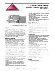
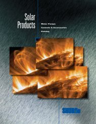
Power <strong>Switch</strong>ing & Controls<br />
for Business-Critical Continuity
24-hour protection no matter<br />
when trouble strikes<br />
ASCO Series 300<br />
Power <strong>Transfer</strong> <strong>Switch</strong>es<br />
for Power Outage Protection<br />
Where would you be<br />
without a constant flow of<br />
electrical power? We often<br />
take for granted that power<br />
will always be around when<br />
we need it. In reality, power<br />
failures are very common.<br />
And when the power goes<br />
out, your business suffers.<br />
Power failures are unpredictable.<br />
They can occur at any<br />
time and for any number of<br />
reasons—a bolt of lightning,<br />
a power surge, a blackout,<br />
an accident or even equipment<br />
failure. They come<br />
without warning and often<br />
at the most inconvenient<br />
times.<br />
It’s for this reason that<br />
many businesses and other<br />
entities have invested in<br />
emergency power backup<br />
systems. Typically, the system<br />
consists of an engine<br />
generator and an automatic<br />
transfer switch (ATS) which<br />
transfers the load from the<br />
utility to the generator.<br />
An ATS with built-in<br />
control logic monitors your<br />
normal power supply and<br />
senses any interruptions.<br />
When the utility power fails,<br />
the ATS automatically starts<br />
the engine and transfers the<br />
load after the generator has<br />
reached proper voltage and<br />
frequency. This happens in<br />
a matter of seconds after<br />
the power failure occurs.<br />
When the utility power has<br />
been restored, the ATS will<br />
automatically switch the load<br />
back, and after a time delay,<br />
it will shut down the engine.<br />
With an <strong>Automatic</strong> <strong>Transfer</strong><br />
<strong>Switch</strong>, you are protected<br />
24 hours a day, seven days a<br />
week.<br />
2
Typical Applications<br />
Telecom<br />
In the telecommunications<br />
industry, providing a high level<br />
of service and dependability is<br />
crucial. Lost power means an<br />
interruption in service for your<br />
customers and lost business<br />
for your company. For instance,<br />
with cell sites scattered across a<br />
wide geographical region and in<br />
many remote areas, the chances<br />
of an interruption in power are<br />
increased, making <strong>Automatic</strong><br />
<strong>Transfer</strong> <strong>Switch</strong>es a valuable<br />
resource at each location. To<br />
maintain dependable service,<br />
each cell site must be monitored<br />
24 hours a day. This can be<br />
very difficult without some<br />
type of remote monitoring and<br />
testing capability. The Series 300<br />
<strong>Transfer</strong> <strong>Switch</strong>, combined with<br />
ASCO’s monitoring and control<br />
management system, is a costeffective,<br />
packaged solution<br />
which can help meet both of<br />
these challenging objectives<br />
without a major investment<br />
at each cell site. With ASCO’s<br />
connectivity solutions you can<br />
remotely monitor and control<br />
numerous sites from around<br />
the corner or around the world.<br />
Agriculture<br />
Maintaining electrical power<br />
is vital to an agriculture operation.<br />
If the flow of power is<br />
interrupted, your operation<br />
could be at risk unless the<br />
backup generator is quickly<br />
activated. A prolonged power<br />
outage can affect numerous<br />
aspects of the operation, from<br />
housing and feeding livestock<br />
to processing and producing<br />
the end product. With<br />
an ASCO Series 300 <strong>Transfer</strong><br />
<strong>Switch</strong>, power will automatically<br />
be transferred over to your<br />
backup generator, eliminating<br />
the need to manually switch<br />
from utility to generator. When<br />
power is restored, the ASCO<br />
Series 300 <strong>Transfer</strong> <strong>Switch</strong> will,<br />
after an adjustable time delay<br />
to allow for utility stabilization,<br />
auto-matically switch the load<br />
back to the utility service.<br />
Commercial / Retail,<br />
Light Industrial<br />
The retail industry is very competitive.<br />
An electrical power<br />
failure can have a dramatic<br />
impact on a retailer’s bottom<br />
line. If power is interrupted<br />
during peak shopping times,<br />
the effect could be extremely<br />
damaging to present and<br />
future business. A power interruption<br />
will not only suspend<br />
shopping, it can also create<br />
safety problems, result in lost<br />
transaction data, lost account<br />
information and damage to<br />
data collection equipment. In<br />
addition, retailers who rely on<br />
controlled climates to protect<br />
valuable inventory could suffer<br />
even greater losses, especially<br />
if the power failure occurs at<br />
a time when no one is available<br />
to rectify the situation. To<br />
avoid any of these power outage<br />
problems, simply install a<br />
backup generator with an ASCO<br />
Series 300 <strong>Transfer</strong> <strong>Switch</strong> and<br />
power outage concerns will be<br />
a thing of the past.<br />
Municipal<br />
The ASCO Series 300 <strong>Transfer</strong><br />
<strong>Switch</strong> can be a critical component<br />
of a municipal government’s<br />
emergency power<br />
backup system. Residents of<br />
townships, cities and counties<br />
rely on police, fire, ambulance/first<br />
aid and other critical<br />
public sector services. An interruption<br />
in power would affect<br />
the ability of emergency services<br />
to effectively respond to<br />
the needs of the community.<br />
When time is a critical factor,<br />
such as when responding to a<br />
fire alarm or an emergency call,<br />
an ASCO Series 300 <strong>Transfer</strong><br />
<strong>Switch</strong> can be a lifesaver,<br />
switching power to the backup<br />
generator. While not all municipal<br />
services are a matter of<br />
life and death, they are always<br />
expected to be there.<br />
3
Series 300 Power <strong>Transfer</strong> <strong>Switch</strong>es<br />
Maximum Reliability & Excellent Value<br />
With a Series 300 <strong>Transfer</strong> <strong>Switch</strong>, you get a product backed by<br />
ASCO Power Technologies, the industry leader responsible for virtually every<br />
major technological advance in the <strong>Transfer</strong> <strong>Switch</strong> industry.<br />
The ASCO Series 300 was designed for one purpose–to automatically<br />
transfer critical loads in the event of a power outage. Each and every<br />
standard component was designed<br />
by ASCO engineers for this purpose.<br />
The rugged construction and proven performance of the ASCO<br />
Series 300 assure the user of many years of complete reliability.<br />
The Series 300 is even designed to handle the extraordinary demands<br />
placed on the switch when starting or restarting stalled motors and<br />
switching high inrush loads.<br />
ASCO’s Series 300 modular, compact design makes it easy to install, inspect<br />
and maintain. All parts are accessible from the front so switch contacts can<br />
be easily inspected.<br />
Features<br />
The Series 300 is listed to UL 1008 standard for <strong>Transfer</strong> <strong>Switch</strong><br />
Equipment and CSA standard C22.2 for automatic transfer switches.<br />
Meets NFPA 110 for Emergency and Standby Power Systems<br />
and the National Electrical Code (NEC) Articles 700, 701 and 702.<br />
30 through 3000 amps in a compact design.<br />
Available to 600 VAC, single or three phase.<br />
True double-throw operation: The single solenoid design is inherently<br />
inter-locked and prevents contacts from stopping between sources<br />
or from being in contact with both sources at the same time.<br />
UL Listed Withstand & Close-On Ratings<br />
<strong>Switch</strong> Ratings<br />
Amps<br />
Available Symmetrical Amperes RMS<br />
When Used<br />
With Current<br />
Limiting Fuses<br />
Maximum<br />
Voltage<br />
When Used<br />
With Specific<br />
Circuit Breakers<br />
30 100,000 480v/60Hz 10,000<br />
70 - 200 200,000 480v/60Hz 22,000<br />
230 100,000 480v/60Hz 22,000<br />
260, 400 200,000 480v/60Hz 42,000<br />
600 200,000 600v/60Hz 42,000<br />
600 200,000 480v/60Hz 50,000<br />
600 200,000 240v/60Hz 65,000<br />
800,1000,1200 200,000 600v/60Hz 65,000<br />
1600, 2000 200,000 600v/60Hz 85,000<br />
2600, 3000 200,000 600v/60Hz 100,000<br />
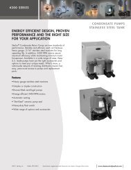
Fig. 1: ASCO Power <strong>Transfer</strong> <strong>Switch</strong> rated<br />
200 amperes shown in Type 3R enclosure<br />
There’s no danger of the Series 300 ATS<br />
transferring loads to a dead source because<br />
the unique ASCO single-solenoid operator<br />
derives power to operate from the source to<br />
which the load is being transferred.<br />
Easy-to-read flush-mounted control and<br />
display panel provides LED indicators<br />
for switch position and source availability.<br />
It also includes test and time-delay bypass<br />
switches as standard features.<br />
Standard engine exerciser for weekly<br />
automatic testing of engine generator set<br />
with or without load.<br />
Adjustable time-delay feature prevents switch<br />
from being activated due to momentary<br />
utility power outages and generator dips.<br />
Supplied with solid neutral termination.<br />
Optional switched neutral pole available.<br />
Accessory kits available.<br />
Available for immediate delivery.<br />
Now available for service entrance<br />
applications. Contact Asco for assistance.<br />
4<br />
Notes: 1. Current – limiting fuse should be Class J type through 400 amps:<br />
use Class L type above 400 - amp fuse rating<br />
2. Refer to publication 1128 for specific manufacturer ’s breakers
Series 300 Power <strong>Transfer</strong> <strong>Switch</strong>es<br />
Designed to Fit Anywhere<br />
The ASCO Series 300 product line represents the most compact<br />
design of automatic power transfer switches in the industry. With<br />
space in electrical closets being at a premium, the use of wall or<br />
floor-mounted ASCO Power <strong>Transfer</strong> <strong>Switch</strong>es assures designers<br />
optimum utilization of space.<br />
All transfer switches through 2000 amps are designed to be<br />
completely front accessible. This permits the enclosures to be<br />
installed flush to the wall and still allows installation of all power<br />
cabling and connections from the front of the switch. Cable entrance<br />
plates are also standard on the 1600 and 2000 amp units to install<br />
optional side-mounted pull boxes for additional cable bending space.<br />
Fig. 2: ASCO Power <strong>Transfer</strong> <strong>Switch</strong><br />
rated 200 amperes<br />
Fig. 3: ASCO Power <strong>Transfer</strong> <strong>Switch</strong><br />
rated 400 amperes<br />
Fig. 4: ASCO Power <strong>Transfer</strong> <strong>Switch</strong><br />
rated 600 Amperes<br />
Fig. 5: ASCO Power <strong>Transfer</strong> <strong>Switch</strong><br />
rated 1000 amperes<br />
Fig. 6: ASCO Power <strong>Transfer</strong> <strong>Switch</strong><br />
rated 2000 amperes shown in Type 3R enclosure<br />
Fig. 7: ASCO Power <strong>Transfer</strong> <strong>Switch</strong><br />
rated 3000 amperes<br />
5
Series 300 Microprocessor Controller<br />
The ASCO Microprocessor Controller is used with all sizes of Power <strong>Transfer</strong> <strong>Switch</strong>es. It represents the most reliable<br />
microprocessor controller in the industry and includes, as standard, all of the voltage, frequency, control, timing and<br />
connectivity functions required for most emergency and standby power applications.<br />
Fig. 8: ASCO Series 300<br />
Microprocessor Controller<br />
Fig. 9: Door-Mounted Control & Display Panel<br />
Control and Display Panel<br />
Easy-to-read flush-mounted control and display panel<br />
provides LED indicators for switch position and source availability.<br />
It also includes test and time-delay bypass switches.<br />
Voltage & Frequency Sensing<br />
Adjustable three-phase, close-differential voltage sensing<br />
on normal source.<br />
Normal source pickup voltage is adjustable to 95% of<br />
nominal; drop-out is adjustable from 70% to 90% of nominal.<br />
Frequency sensing on emergency source. Pickup at 95% and<br />
dropout at 85% of nominal.<br />
Time Delays<br />
Adjustable time delay to override momentary normal<br />
source outages to delay all transfer switch and enginestarting<br />
signals.<br />
<strong>Transfer</strong> to emergency time delay––Adjustable from 0 to 5<br />
minutes for controlled timing of load transfer to emergency.<br />
Re-transfer to normal time delay––Adjustable to 30 minutes.<br />
Five-minute unloaded running time delay for emergency<br />
engine generator cool down.<br />
Four-second time delay to ignore momentary voltage and<br />
frequency transients during initial genset loading.<br />
Standard Selectable Features<br />
Inphase monitor to transfer motor loads, without any<br />
intentional off time, to prevent inrush currents from<br />
exceeding normal starting levels.<br />
Engine exerciser to automatically test backup generator<br />
each week—Includes control switch for testing with or<br />
without load.<br />
Selective load disconnect, double-throw contact to operate<br />
at an adjustable 0 to 20 second adjustable time delay prior<br />
to transfer and reset 0 to 20 seconds after transfer.<br />
60 Hz or 50 Hz selectable switch.<br />
Three-phase/single-phase selectable switch.<br />
Remote Control Features<br />
Terminal provisions for connecting:<br />
Remote test switch.<br />
Remote contact for test or for peak shaving applications.<br />
Circuit will be automatically bypassed if emergency<br />
source fails.<br />
Remote time-delay bypass switch.<br />
6
Series 300 Microprocessor Controller<br />
Battery to<br />
Maintain Engine<br />
Exerciser Clock<br />
Settings<br />
Simple and Accurate<br />
Adjustment of<br />
Voltage, Frequency<br />
and Time-Delay<br />
Settings Without<br />
Need for Meters<br />
and Variable<br />
Power Supplies<br />
Dip <strong>Switch</strong>es for Enabling<br />
Built-In Control Functions<br />
Customer Control<br />
Interfaces<br />
Re-transfer to<br />
Normal Adjustable<br />
Time Delay<br />
<strong>Transfer</strong> to<br />
Emergency Adjustable<br />
Time Delay<br />
Serial<br />
Communication Port<br />
Fig. 10: Microprocessor Controller<br />
Performance Features<br />
600 volt spacing per UL and CSA standards.<br />
Interfacing relays are industrial grade, plug-in type with dust covers.<br />
Meets or exceeds the requirements for Electromagnetic Compatibility (EMC).<br />
ANSI C37.90A/IEEE472 Voltage<br />
Surge Test<br />
NEMA ICS-109.21 Impulse<br />
Withstand Test<br />
Digital circuitry isolated from<br />
line voltages<br />
IEC 801-2 Electrostatic<br />
discharge (ESD) immunity<br />
ENV50140 and IEC 803-1: Radiated<br />
electromagnetic field immunity<br />
IEC 801-4 Electrical fast transient<br />
(EFT) immunity<br />
ENV50142 Surge transient immunity<br />
ENV50141: Conducted<br />
radio-frequency field immunity<br />
EN55011: Group 1, Class A conducted and<br />
radiated emissions<br />
Optically isolated RS-485 Serial Port<br />
EN61000- 4-11 voltage dips and interruptions<br />
immunity<br />
7
Series 300 ATS Optional Accessories<br />
Accessory 11BG<br />
A programmable engine exerciser that provides for weekly or bi-weekly<br />
operation, includes one form C contact for source availability of normal<br />
and one contact for availability of emergency (contact rating 2 amps @ 30<br />
Vdc, 0.5 amp @ 125 Vac resistive). The programmable engine exerciser<br />
incorporates a 7 day or 14 day time base with a digital readout display.<br />
Includes “with or without” load control selection for exerciser period.<br />
Accessory 14AA/14BA<br />
Auxiliary contacts to indicate position of main contacts. Two (2) for normal<br />
and two (2) for emergency position (one set is standard).<br />
Accessory 44A<br />
Strip Heater with thermostat for extremely cold areas to prevent<br />
condensation and freezing of this condensation. External 120 volt power<br />
source required.<br />
Fig. 11: Programmable Engine Exerciser<br />
with Source Availability Contacts<br />
(Accessory 11BG)<br />
Accessory 44G<br />
Strip Heater with thermostat, wired to load terminals: 208-240,<br />
360-380, 460-480, 550-600 volts. Contains wiring harnesses for<br />
all transfer switch sizes.<br />
Accessory 72A /72E<br />
*See “Connectivity Products”, Page 18<br />
Accessory 123<br />
A protective window that includes a poly-carbonate frame and weather<br />
gasket to provide secure access to the membrane interface for the type<br />
1 enclosures. This lockable cover is an alternative to providing 3R secure<br />
enclosures.<br />
Fig. 12: Strip Heater Kit<br />
(Accessory 44G)<br />
Field Conversion Kits for Series 300 <strong>Transfer</strong> <strong>Switch</strong>es<br />
Kit No. Description<br />
K629830 Engine Exerciser and source availability contacts (Acc. 11BG)<br />
K613127-001 Strip Heater Kit (125 watt) 120 volt (Acc. 44A)<br />
K613127-002 Strip Heater Kit (125 watt) 208-480 volt (Acc. 44G)<br />
K609027 Cable Pull Box (1600-2000 amp)<br />
K473872-001 6 FT Extension Harness 1<br />
K755257-001 Serial Module with or without power manager (Acc. 72A)<br />
K754603-001 Connectivity Module with or without power manager (Acc. 72E)<br />
K778330-001 Window Kit (Acc. 123)<br />
1. For 30-200 Amp switches only, not available for 300SE, or 300L<br />
Fig. 13: Window Kit<br />
(Accessory 123)<br />
8
Series 386 Non-<strong>Automatic</strong> Power <strong>Transfer</strong> <strong>Switch</strong>es<br />
User-Initiated Control<br />
ASCO 386 non-automatic transfer switches are generally used in applications where operating personnel are available<br />
and the load is not an emergency type requiring automatic transfer of power. The power-switching mechanism<br />
and controller is the same hardware used on the highly reliable ASCO Series 300 transfer switches. ASCO 386s are<br />
furnished as standard with a momentary-type selector switch to initiate transfer and re-transfer. They can also be<br />
arranged for remote control via ASCO’s connectivity products.<br />
Fig. 14: ASCO 386 400 Amp<br />
Type 1 Enclosure w/Optional<br />
Accessories 9C, 9D Source<br />
Availability Lights<br />
Fig. 15: Control and Display Panel<br />
Electrical Features:<br />
Listed under UL 1008, CSA certified:<br />
- UL listed through 480 VAC.<br />
- CSA certified through 600 VAC.<br />
Door-mounted selector switch for local, manually initiated<br />
electrical control.<br />
Sizes from 30 through 3000 amps.<br />
Available to 600 VAC, 50 or 60 Hz.<br />
Rated for all classes of load transfer.<br />
100% tungsten load ratings through 400 amps.<br />
Designed for emergency and standby applications.<br />
Same withstand and close-on rating as Series 300.<br />
Standard Selectable Control Features:<br />
Inphase monitor to transfer motor loads between live sources,<br />
without any intentional off time, to prevent inrush currents from<br />
exceeding normal starting levels.<br />
Selective load disconnect, double-throw contact to<br />
operate at an adjustable 0 to 20 second time delay prior to transfer<br />
and reset 0 to 20 seconds after transfer.<br />
High/Low nominal voltage setting. Allows user to adjust for source<br />
low reduced voltage conditions in remote areas.<br />
60 Hz or 50 Hz selectable switch.<br />
Single/Three-phase selectable switch.<br />
Control Features:<br />
<strong>Switch</strong> position indicating signal lights.<br />
One auxiliary contact closed when transfer switch is<br />
connected to normal and one closed on emergency,<br />
standard feature 14A/14B.<br />
Optional Accessories:<br />
6Q Key-operated, momentary source selector switch<br />
furnished instead of the standard selector switch.<br />
9C, 9D Source availability lights to provide operator with a local<br />
indication of power source availability.<br />
Accessory 14AA/14BA auxiliary contacts to indicate<br />
position of main contacts. Two (2) for normal position and two<br />
(2) for emergency position (one set is standard).<br />
72A Serial module (5110) is used to allow local or remote<br />
communications with ASCO POWERQUEST ® connectivity<br />
products.<br />
Special Enclosures<br />
(Specify by appropriate code in catalog number):<br />
Type 3R: Rain-tight<br />
Type 4: Weatherproof<br />
Type 12: Oil Tight<br />
72E Connectivity Module 5150 is used to bring several<br />
different serial devices that communicate at different<br />
baud rates and with different protocols to a common<br />
Ethernet media.<br />
9
To order an ASCO Series 300 Power <strong>Transfer</strong> <strong>Switch</strong>, complete the following catalog number:<br />
300 + B + 3 + 600 + N + 1 + X + C + 11CD + 480 V 60 Hz<br />
Product<br />
300<br />
Neutral<br />
Code<br />
Blank<br />
Solid<br />
Neutral<br />
B 1<br />
<strong>Switch</strong>ed<br />
Neutral<br />
Poles Amperes Voltage<br />
Code<br />
2 poles,<br />
1Ø<br />
3 poles,<br />
3Ø<br />
Controller<br />
Options<br />
Enclosure<br />
Blank Open Type<br />
Continuous A 3 115<br />
Insert “X” C Type 1<br />
B 3<br />
If optional<br />
(Standard)<br />
rating<br />
120 1<br />
C 208<br />
accessories<br />
F Type 3R<br />
D 220<br />
are required<br />
30, 70, 104, E 230<br />
G Type 4 2<br />
150, 200 4 , F 240<br />
H Type 4X<br />
230 4 , 260, H 380<br />
J 400<br />
400, 600,<br />
L Type 12 2<br />
K 415<br />
800, 1000,<br />
Type 3R<br />
L 440<br />
M Secure<br />
1200, 1600, M 460<br />
2000 N 480<br />
Type 4<br />
2600 5 , 3000 5 Q 575<br />
N<br />
Secure<br />
R 600<br />
Type 4X 6<br />
Secure<br />
P<br />
Double<br />
Door SS<br />
Type 3RX 6,7<br />
Secure<br />
Double<br />
Door SS<br />
To order an ASCO Series 386 <strong>Transfer</strong> <strong>Switch</strong>, complete the following catalog number:<br />
Optional<br />
Accessories<br />
11BG<br />
Programmable<br />
Engine Exerciser<br />
14AA/14BA<br />
Auxiliary Contacts<br />
(2 sets)<br />
44A, 44G<br />
Strip Heater w/<br />
Thermostat<br />
72A<br />
Serial Module<br />
72E<br />
Connectivity<br />
Module<br />
123<br />
Window<br />
Kit<br />
Specific<br />
Volt & Freq<br />
This information<br />
is necessary<br />
to allow correct<br />
control settings<br />
prior to shipment<br />
386 + B + 3 + 600 + N + 1 + X + C + 9C/9D + 480 V 60 Hz<br />
Product<br />
386<br />
Notes:<br />
Neutral<br />
Code<br />
A<br />
Solid<br />
Neutral<br />
B 1<br />
<strong>Switch</strong>ed<br />
Neutral<br />
Series 300 & 386 <strong>Transfer</strong> <strong>Switch</strong> Ordering Information<br />
Phase<br />
Poles<br />
2 poles,<br />
1Ø<br />
3 poles,<br />
3Ø<br />
Amperes<br />
Continuous<br />
rating<br />
30, 70, 100,<br />
150, 200 4 ,<br />
230 4 , 260,<br />
400, 600,<br />
800, 1000,<br />
1200, 1600,<br />
2000, 2600,<br />
3000 5<br />
Voltage<br />
Code<br />
A 3<br />
B 3<br />
C<br />
D<br />
E<br />
F<br />
H<br />
J<br />
K<br />
L<br />
M<br />
N<br />
Q<br />
R<br />
115<br />
120<br />
208<br />
220<br />
230<br />
240<br />
380<br />
400<br />
415<br />
440<br />
460<br />
480<br />
575<br />
600<br />
Controller<br />
Options<br />
1 Insert “X”<br />
If optional<br />
accessories<br />
are required<br />
Enclosure<br />
Blank Open Type<br />
C Type 1<br />
(Standard)<br />
1. Specify neutral code “C” for 260 and 400 amperes only.<br />
2. Available 30-1000, and 1600 amps. Use Type 3R for 1200, 2000, 2600 and 3000 amp applications.<br />
3. 115-120 volt available 30-400 amps only. For other voltages contact ASCO.<br />
4. 200 and 230 amp rated switches for use with copper cable only.<br />
5. Secure 3R type provided as standard for 2600-3000 amp when outdoor enclosure is required.<br />
6. Type 304 Stainless Steel is standard. Suitable for indoor or outdoor use where there may be caustic or alkali<br />
chemicals in use. To provide an improved reduction in corrosion of salt and some chemicals, optional type 316<br />
Stainless Steel is recommended. This is a preferred choice for marine environments.<br />
7. Available on switches rated 1200, 2000, 2600, and 3000 Amps.<br />
Extended Warranties for Series 300 <strong>Transfer</strong> <strong>Switch</strong>es<br />
Catalog No.<br />
Description<br />
R<br />
F<br />
G<br />
H<br />
L<br />
M<br />
N<br />
P<br />
R<br />
Type 3R<br />
Type 4 2<br />
Type 4X<br />
Type 12 2<br />
Type 3R<br />
Secure<br />
Type 4<br />
Secure<br />
Type 4X 6<br />
Secure<br />
Double<br />
Door SS<br />
Type 3RX 6,7<br />
Secure<br />
Double<br />
Door SS<br />
Optional<br />
Accessories<br />
6Q<br />
Key-Operated<br />
Control<br />
9C/9D<br />
Source<br />
Availability Lights<br />
14AA/14BA<br />
Auxiliary Contacts<br />
72A<br />
Serial Module<br />
All Accessories<br />
72E<br />
Connectivity<br />
Module<br />
Specific<br />
Volt & Freq<br />
This information<br />
is necessary<br />
to allow correct<br />
control settings<br />
prior to shipment<br />
10<br />
2EXW300<br />
3EXW300<br />
4EXW300<br />
5EXW300<br />
Two-Year Extended Warranty (Parts & Labor)<br />
Three-Year Extended Warranty (Parts & Labor)<br />
Four-Year Extended Warranty (Parts & Labor)<br />
Five-Year Extended Warranty (Parts & Labor)
Series 300 & 386 <strong>Transfer</strong> <strong>Switch</strong> Dimensions and Shipping Weights<br />
UL Type 1 Enclosure 4<br />
<strong>Switch</strong> Rating<br />
Amps<br />
Phase<br />
Poles<br />
Neutral<br />
Code<br />
2<br />
A<br />
30, 70, 100*, 104 2<br />
B<br />
150, 200<br />
3<br />
A<br />
*Series 386 only<br />
3<br />
B<br />
2<br />
A<br />
2<br />
230 3 B 3 or C<br />
, 260, 400<br />
3<br />
A<br />
3 B 3 or C<br />
2<br />
A<br />
2<br />
B<br />
600<br />
3<br />
A<br />
3<br />
B<br />
2<br />
A<br />
2<br />
800, 1000<br />
B<br />
3<br />
A<br />
3<br />
B<br />
2<br />
A<br />
2<br />
B<br />
1200<br />
3<br />
A<br />
3<br />
B<br />
3<br />
1600, 2000 1<br />
A<br />
3<br />
B<br />
2600, 3000 2 3<br />
A<br />
3<br />
B<br />
UL Type 3R, 4 or 12 Enclosure 1,4,5,6<br />
<strong>Switch</strong> Rating<br />
Amps<br />
30, 70, 100*, 104<br />
150, 200<br />
*Series 386 only<br />
230 3 , 260, 400<br />
600<br />
800, 1000<br />
1200 6<br />
1600, 2000 2<br />
2600, 3000<br />
Phase<br />
Poles<br />
2<br />
2<br />
3<br />
3<br />
2<br />
2<br />
3<br />
3<br />
2<br />
2<br />
3<br />
3<br />
2<br />
2<br />
3<br />
3<br />
2<br />
2<br />
3<br />
3<br />
3<br />
3<br />
3<br />
3<br />
Neutral<br />
Code<br />
A<br />
B<br />
A<br />
B<br />
A<br />
B 3 or C<br />
A<br />
B 3 or C<br />
A<br />
B<br />
A<br />
B<br />
A<br />
B<br />
A<br />
B<br />
A<br />
B<br />
A<br />
B<br />
A<br />
B<br />
A<br />
B<br />
Dimensions, In. (mm)<br />
Width Height Depth<br />
17 1/2 (445)<br />
17 1/2 (445)<br />
17 1/2 (445)<br />
17 1/2 (445)<br />
18 (457)<br />
18 (457)<br />
18 (457)<br />
18 (457)<br />
24 (610)<br />
24 (610)<br />
24 (610)<br />
24 (610)<br />
34 (864)<br />
34 (864)<br />
34 (864)<br />
34 (864)<br />
38 (965)<br />
38 (965)<br />
38 (965)<br />
38 (965)<br />
38 (965)<br />
38 (965)<br />
38 (965)<br />
38 (965)<br />
31 (787)<br />
31 (787)<br />
31 (787)<br />
31 (787)<br />
48 (1219)<br />
48 (1219)<br />
48 (1219)<br />
48 (1219)<br />
63 (1600)<br />
63 (1600)<br />
63 (1600)<br />
63 (1600)<br />
72 (1829)<br />
72 (1829)<br />
72 (1829)<br />
72 (1829)<br />
87 (2210)<br />
87 (2210)<br />
87 (2210)<br />
87 (2210)<br />
87 (2210)<br />
87 (2210)<br />
91 (2311)<br />
91 (2311)<br />
11 5/8 (295)<br />
11 5/8 (295)<br />
11 5/8 (295)<br />
11 5/8 (295)<br />
13 (330)<br />
13 (330)<br />
13 (330)<br />
13 (330)<br />
17 (432)<br />
17 (432)<br />
17 (432)<br />
17 (432)<br />
20 (508)<br />
20 (508)<br />
20 (508)<br />
20 (508)<br />
24 (610)<br />
24 (610)<br />
24 (610)<br />
24 (610)<br />
24 (610)<br />
24 (610)<br />
60 (1524)<br />
60 (1524)<br />
Dimensions, In. (mm)<br />
Width Height Depth<br />
17 1/2 (445)<br />
17 1/2 (445)<br />
17 1/2 (445)<br />
17 1/2 (445)<br />
18 (458)<br />
18 (458)<br />
18 (458)<br />
18 (458)<br />
24 (610)<br />
24 (610)<br />
24 (610)<br />
24 (610)<br />
34 (864)<br />
34 (864)<br />
34 (864)<br />
34 (864)<br />
41 (1043)<br />
41 (1043)<br />
41 (1043)<br />
41 (1043)<br />
41 (1043)<br />
41 (1043)<br />
41 (1043)<br />
41 (1043)<br />
35 (886)<br />
35 (886)<br />
35 (886)<br />
35 (886)<br />
50 1/2 (1284)<br />
50 1/2 (1284)<br />
50 1/2 (1284)<br />
50 1/2 (1284)<br />
63 (1602)<br />
63 (1602)<br />
63 (1602)<br />
63 (1602)<br />
75 (1907)<br />
75 (1907)<br />
75 (1907)<br />
75 (1907)<br />
94 1/2 (2403)<br />
94 1/2 (2403)<br />
94 1/2 (2403)<br />
94 1/2 (2403)<br />
95 1/2 (2428)<br />
95 1/2 (2428)<br />
95 1/3 (2424)<br />
95 1/3 (2424)<br />
11 5/8 (295)<br />
11 5/8 (295)<br />
11 5/8 (295)<br />
11 5/8 (295)<br />
14 1/3 (364)<br />
14 1/3 (364)<br />
14 1/3 (364)<br />
14 1/3 (364)<br />
18.50 (470)<br />
18.50 (470)<br />
18.50 (470)<br />
18.50 (470)<br />
20 (508)<br />
20 (508)<br />
20 (508)<br />
20 (508)<br />
33 1/2 (852)<br />
33 1/2 (852)<br />
33 1/2 (852)<br />
33 1/2 (852)<br />
62 (1577)<br />
62 (1577)<br />
74 (1882)<br />
74 (1882)<br />
Approx. Shipping<br />
Weight Lb. (kg)<br />
69 (32)<br />
73 (33)<br />
73 (33)<br />
75 (34)<br />
100 (45)<br />
110 (50)<br />
100 (45)<br />
120 (55)<br />
263 (119)<br />
270 (122)<br />
270 (122)<br />
277 (126)<br />
450 (204)<br />
475 (217)<br />
475 (217)<br />
500 (228)<br />
685 (312)<br />
705 (321)<br />
705 (321)<br />
725 (328)<br />
925 (419)<br />
975 (441)<br />
1700 (771)<br />
2135 (969)<br />
Approx. Shipping<br />
Weight Lb. (kg)<br />
84 (38)<br />
87 (40)<br />
87 (40)<br />
90 (41)<br />
132 (60)<br />
140 (63)<br />
140 (63)<br />
148 (67)<br />
664 (300)<br />
672 (303)<br />
672 (303)<br />
680 (307)<br />
664 (300)<br />
672 (303)<br />
672 (303)<br />
680 (307)<br />
1131 (513)<br />
1160 (526)<br />
1160 (526)<br />
1189 (539)<br />
1810 (817)<br />
1860 (843)<br />
2005 (905)<br />
2070 (938)<br />
Notes:<br />
1. Unit is designed for top cable<br />
entry of emergency & load and<br />
bottom entry of normal. A cable<br />
pull box is also available for all<br />
top or bottom cable access when<br />
required (optional accessory kit<br />
#K609027). Not required for type<br />
3R, 4X & 12 enclosures where<br />
available.<br />
2. Enclosures for 2600, 3000 amps<br />
are free-standing with removable<br />
top, sides & back.<br />
3. Neutral Code “B” for 230 amperes<br />
only.<br />
4. Dimensional data is approximate<br />
and subject to change. Certified<br />
dimensions available upon<br />
request.<br />
Notes:<br />
1. 30-1000 amps non-secure enclosure.<br />
1200-3000 amps secure<br />
enclosure<br />
2. When climate conditions at installation<br />
site present condensation<br />
risk, special precautions<br />
should be taken, such as the<br />
inclusion of space heaters, to<br />
prevent interior condensation and<br />
freezing of this condensation.<br />
3. Neutral code “B” for 230 amperes<br />
only.<br />
4. Dimensions for switch sizes 30 -<br />
1000 amperes suitable for Type<br />
3R, 4, or 12 non secure enclosure,<br />
1200 -3000 amperes only suitable<br />
for type 3R.<br />
5. For 1200 ampere type 4, or 12<br />
use 1600 amperes secure enclosure<br />
dimensions.<br />
6. Dimensional data is approximate<br />
and subject to change. Certified<br />
dimensions available upon<br />
request.<br />
Series 300 & 386 External Power Connections<br />
Sizes UL-Listed Solderless Screw-Type Terminals<br />
<strong>Switch</strong> Rating<br />
(Amps)<br />
30 - 230 2<br />
260, 400<br />
600<br />
800, 1000, 1200<br />
1600, 2000<br />
2600, 3000<br />
Ranges of AL-CU Wire Sizes<br />
(Unless Specified Copper Only)<br />
One #14 to 4/0 AWG<br />
Two 1/0 AWG to 250 MCM<br />
or One #4 AWG to 600 MCM<br />
Two 2/0 AWG to 600 MCM<br />
Four 1/0 to 600 MCM<br />
Six 1/0 to 600 MCM<br />
Twelve 3/0 to 600 MCM<br />
Notes:<br />
1. All Series 300 switches are furnished with a solid neutral plate<br />
(unless switched neutral configuration is specified) and terminal<br />
lugs. Specify “A” in catalog number to order a neutral plate on the<br />
series 386 switches.<br />
2. 200 and 230 amp rated switches for use with copper cable only.<br />
Refer to paragraph 310.15 of the NEC for additional information.<br />
3. Use wire rated 75 o C minimum for all power connections.<br />
11
Series 300SE Power <strong>Transfer</strong> <strong>Switch</strong><br />
The ASCO Service Entrance Power <strong>Transfer</strong> <strong>Switch</strong> combines<br />
automatic power switching with the necessary disconnecting,<br />
grounding, and bonding required for use as service entrance<br />
equipment. The power transfer switch meets all National Electrical<br />
Code requirements for service entrance use. <strong>Transfer</strong> switches<br />
generally are installed at facilities that have a single utility feed and<br />
a single emergency power source.<br />
600 - 3000 Amp<br />
Construction<br />
ASCO Series 300SE products use two types of construction.<br />
Products 400 amperes or less, utilize a single enclosure including<br />
a service (utility source) disconnect circuit breaker, as well as the<br />
power transfer switch, grounding and bonding provisions.<br />
Products 600 amperes and above, utilize a multi-section<br />
switchboard construction including a service equipment section<br />
containing the service (utility source) disconnect circuit breaker,<br />
grounding, and bonding provisions. A second section contains<br />
the power transfer switch.<br />
Product Features:<br />
Suitable for use as service entrance equipment.<br />
Listed to UL 891 (standard for switchboards) for<br />
600 - 3000 amps, sizes and UL 1008 (standard for panel-boards)<br />
for 70 - 400 amps.<br />
<strong>Automatic</strong> <strong>Transfer</strong> <strong>Switch</strong> is listed to UL 1008 for total<br />
system loads<br />
Sizes available from 70 - 3000 amps, 600 VAC, 50 or 60 Hz,<br />
single or three phase<br />
Silver plated copper ground and neutral bus solderless<br />
screw type terminals<br />
Ground fault trip protection provided on sizes 1000 amps<br />
and above<br />
Available with solid or switched neutral<br />
70 - 400 Amp<br />
Construction<br />
Fig. 16: ASCO Series 300<br />
SE Rated 800 amperes Type<br />
1 enclosure with Service<br />
Entrance Equipment<br />
Fig. 17: ASCO Series 300 SE<br />
rated 200 amperes in Type 1<br />
enclosure with single source<br />
breakers<br />
12<br />
To order an ASCO Series 300SE Power <strong>Transfer</strong> <strong>Switch</strong>, complete the following catalog number:<br />
3AUS + B + 3 + 400 + N + 1 + X + C + 11CD + 240 V/60<br />
Product<br />
3AUS<br />
Notes:<br />
Neutral<br />
Code<br />
B 1<br />
<strong>Switch</strong>ed<br />
Neutral<br />
Series 300SE <strong>Transfer</strong> <strong>Switch</strong> Ordering Information<br />
Phase<br />
Poles<br />
2 poles,<br />
1Ø<br />
3 poles,<br />
3Ø<br />
Amperes<br />
Continuous<br />
Rating<br />
70, 100,<br />
150, 200 6 ,<br />
225 6 , 250,<br />
400, 600,<br />
800, 1000,<br />
1200, 1600,<br />
2000<br />
2500, 3000<br />
Voltage<br />
Code<br />
A 3<br />
B 3<br />
C<br />
D<br />
E<br />
F<br />
H<br />
J<br />
K<br />
L<br />
M<br />
N<br />
Q<br />
R<br />
115<br />
120<br />
208<br />
220<br />
230<br />
240<br />
380<br />
400<br />
415<br />
440<br />
460<br />
480<br />
575<br />
600<br />
1. Specify neutral code “C” for 250 and 400 amperes only.<br />
2. Available 70-1000 ampacity. Use Type 3R for 1200-3000 amp applications.<br />
3. 115-120 volt available 150-400 amps only.<br />
4. A solid neutral is standard on 3AUS.<br />
5. For switch sizes 70 - 225 amperes only.<br />
Controller<br />
Options<br />
1 Insert “X”<br />
If optional<br />
accessories<br />
are required<br />
Enclosure<br />
Blank Open Type<br />
C Type 1<br />
(Standard)<br />
F Type 3R<br />
G Type 4 2<br />
H Type 4X<br />
L Type 12 2<br />
M Type 3R<br />
Secure<br />
N Type 4<br />
Secure<br />
Type 4X 6<br />
P Secure<br />
Double<br />
Door SS<br />
Type 3RX 7,8<br />
R Secure<br />
Double<br />
Door SS<br />
Optional<br />
Accessories<br />
11BG<br />
Programmable Engine<br />
Exerciser<br />
14AA/14BA<br />
Auxiliary Contacts<br />
(2 sets)<br />
44G<br />
Strip Heater<br />
w/Thermostat<br />
72A<br />
Serial Module<br />
72E Connectivity<br />
Module<br />
73A Surge Suppressor<br />
6. 200, 225 amp rated switch suitable for use with copper cable only.<br />
7. Type 316 Stainless Steel is standard. It provides an improved reduction in corrosion<br />
of salt and some chemicals. It is the preferred choice for marine environments.<br />
8. Available only on switches rated 1200, 2000, 2600, and 3000 Amps.<br />
Specific<br />
Volt & Freq<br />
This<br />
information<br />
is necessary<br />
to allow<br />
correct<br />
control<br />
settings prior<br />
to shipment
Series 300SE <strong>Transfer</strong> <strong>Switch</strong> Dimensions and Shipping Weights<br />
UL Type 1 Enclosure 4<br />
<strong>Switch</strong> Rating<br />
Phase Neutral<br />
Amps<br />
Poles Code<br />
2<br />
STD<br />
70, 100 ,150,<br />
2<br />
B<br />
200, 225<br />
3<br />
STD<br />
3<br />
B<br />
2<br />
STD<br />
2<br />
C<br />
250, 400<br />
3<br />
STD<br />
3<br />
C<br />
2<br />
STD<br />
2<br />
600 1 , 800 1<br />
B<br />
3<br />
STD<br />
3<br />
B<br />
2<br />
STD<br />
2<br />
1000 1 , 1200 1<br />
B<br />
3<br />
STD<br />
3<br />
B<br />
3<br />
1600 1 , 2000 1<br />
STD<br />
3<br />
B<br />
2500 1 , 3000 1 3<br />
STD<br />
3<br />
B<br />
Dimensions, In. (mm)<br />
Width Height Depth<br />
36.5 (927)<br />
48.5 (1232)<br />
13.25 (337)<br />
36.5 (927)<br />
48.5 (1232)<br />
13.25 (337)<br />
36.5 (927)<br />
48.5 (1232)<br />
13.25 (337)<br />
36.5 (927)<br />
48.5 (1232)<br />
13.25 (337)<br />
36.5 (927)<br />
48.5 (1232)<br />
13.25 (337)<br />
36.5 (927)<br />
48.5 (1232)<br />
13.25 (337)<br />
36.5 (927)<br />
48.5 (1232)<br />
13.25 (337)<br />
36.5 (927)<br />
48.5 (1232)<br />
13.25 (337)<br />
38 (965)<br />
91 (2311)<br />
28 (711)<br />
38 (965)<br />
91 (2311)<br />
28 (711)<br />
38 (965)<br />
91 (2311)<br />
28 (711)<br />
38 (965)<br />
91 (2311)<br />
28 (711)<br />
38 (965)<br />
91 (2311)<br />
48 (1218)<br />
38 (965)<br />
91 (2311)<br />
48 (1218)<br />
38 (965)<br />
91 (2311)<br />
48 (1218)<br />
38 (965)<br />
91 (2311)<br />
48 (1218)<br />
38 (965)<br />
91 (2311)<br />
48 (1218)<br />
38 (965)<br />
91 (2311)<br />
48 (1218)<br />
38 (965)<br />
91 (2311)<br />
72 (1829)<br />
38 (965)<br />
91 (2311)<br />
72 (1829)<br />
Approx. Shipping<br />
Weight Lb. (kg)<br />
400 (185)<br />
408 (188)<br />
408 (188)<br />
416 (192)<br />
400 (185)<br />
408 (188)<br />
408 (188)<br />
416 (192)<br />
800 (370)<br />
820 (378)<br />
820 (378)<br />
846 (390)<br />
1085 (501)<br />
1105 (510)<br />
1105 (510)<br />
1134 (523)<br />
2590 (1198)<br />
2640 (1218)<br />
4590 (2118)<br />
4655 (2148)<br />
UL Type 3R Enclosure 4<br />
<strong>Switch</strong> Rating<br />
Phase Neutral<br />
Amps<br />
Poles Code<br />
2<br />
STD<br />
70, 100 ,150, 200, 225<br />
2<br />
B<br />
must specify<br />
3<br />
STD<br />
3<br />
B<br />
2<br />
STD<br />
2<br />
C<br />
250, 400<br />
3<br />
STD<br />
3<br />
C<br />
2<br />
STD<br />
2<br />
600 1 , 800 1<br />
B<br />
3<br />
STD<br />
3<br />
B<br />
2<br />
STD<br />
2<br />
1000 1 , 1200 1<br />
B<br />
3<br />
STD<br />
3<br />
B<br />
3<br />
1600 1 , 2000 1<br />
STD<br />
3<br />
B<br />
2500 1 , 3000 1 3<br />
STD<br />
3<br />
B<br />
Notes: 1. Unit is designed for top and bottom cable entry for all services<br />
and load.<br />
2. Enclosures for 600 – 3000 amps are freestanding.<br />
3. When temperatures below 32° F can be experienced, special precautions<br />
should be taken, such as the inclusion of strip heaters, to<br />
prevent condensation and freezing of this condensation. This is<br />
Dimensions, In. (mm)<br />
Width Height Depth<br />
36(914)<br />
48(1219)<br />
16 (406)<br />
36(914)<br />
48(1219)<br />
16 (406)<br />
36(914)<br />
48(1219)<br />
16 (406)<br />
36(914)<br />
48(1219)<br />
16 (406)<br />
36(914)<br />
48(1219)<br />
16 (406)<br />
36(914)<br />
48(1219)<br />
16 (406)<br />
36(914)<br />
48(1219)<br />
16 (406)<br />
36(914)<br />
48(1219)<br />
16 (406)<br />
41(1041)<br />
95.5(2426)<br />
34(864)<br />
41(1041)<br />
95.5(2426)<br />
34(864)<br />
41(1041)<br />
95.5(2426)<br />
34(864)<br />
41(1041)<br />
95.5(2426)<br />
34(864)<br />
41(1041)<br />
95.5(2426)<br />
62(1575)<br />
41(1041)<br />
95.5(2426)<br />
62(1575)<br />
41(1041)<br />
95.5(2426)<br />
62(1575)<br />
41(1041)<br />
95.5(2426)<br />
62(1575)<br />
41(1041)<br />
95.5(2426)<br />
62(1575)<br />
41(1041)<br />
95.5(2426)<br />
62(1575)<br />
41(1041)<br />
96(2438)<br />
85(2159)<br />
41(1041)<br />
96(2438)<br />
85(2159)<br />
Approx. Shipping<br />
Weight Lb. (kg)<br />
180 (83)<br />
188 (87)<br />
188 (87)<br />
196 (90)<br />
440 (203)<br />
448 (207)<br />
448 (207)<br />
485 (225)<br />
990 (458)<br />
1010 (467)<br />
1010 (467)<br />
1036 (479)<br />
1305 (604)<br />
1325 (613)<br />
1325 (613)<br />
1354 (626)<br />
2890 (1337)<br />
2940 (1360)<br />
5350 (2474)<br />
5415 (2504)<br />
particularly important when environmental enclosures<br />
(Type 3R, 4 & 12) are ordered for installation outdoors. See Optional<br />
Accessories page for space heater options (acc. 44G).<br />
4. Dimensional data is approximate and subject to change. Certified<br />
dimensions available upon request.<br />
Extended Warranties for<br />
Series 300SE <strong>Transfer</strong> <strong>Switch</strong>es<br />
Catalog No.<br />
2EXW300SE<br />
3EXW300SE<br />
4EXW300SE<br />
5EXW300SE<br />
Description<br />
Two-Year Extended Warranty (Parts & Labor)<br />
Three-Year Extended Warranty (Parts & Labor)<br />
Four-Year Extended Warranty (Parts & Labor)<br />
Five-Year Extended Warranty (Parts & Labor)<br />
Series 300SE AIC Rating<br />
<strong>Switch</strong> Rating<br />
70, 100, 150, 200, 225<br />
250, 400<br />
600<br />
800, 1000,1200, 1600, 2000<br />
2500, 3000<br />
AIC Rating<br />
25,000<br />
35,000<br />
50,000<br />
65,000<br />
100,000<br />
Voltage<br />
480<br />
480<br />
480<br />
480<br />
480<br />
Series 300SE External Power Connections<br />
Sizes UL-Listed Solderless Screw-Type Terminals<br />
<strong>Switch</strong> Rating<br />
70, 100,<br />
150, 200 * , 225 *<br />
250, 400<br />
600<br />
800, 1000, 1200<br />
1600, 2000<br />
2500<br />
3000<br />
Ranges of AL-CU Wire Sizes<br />
(Unless Specified Copper Only)<br />
One #14 to 4/0 AWG<br />
Two 1/0 AWG to 250 MCM or One #4 AWG to 600 MCM<br />
Two 1/0 AWG to 600 MCM<br />
Four 1/0 to 600 MCM<br />
Six 1/0 to 600 MCM<br />
Twelve 3/0 to 600 MCM<br />
Twelve 3/0 to 600 MCM<br />
Note: All Series 300SE switches are furnished with a solid neutral plate<br />
(unless switched neutral configuration is specified) and terminal lugs.<br />
* 200 and 225 amp rated switch for use with copper cable only.<br />
13
Series 300L Power <strong>Transfer</strong> Load Center<br />
• Conventional double throw<br />
transfer switch configuration<br />
• <strong>Automatic</strong> <strong>Transfer</strong> <strong>Switch</strong> is listed<br />
to UL1008, the standard for <strong>Transfer</strong><br />
<strong>Switch</strong> Equipment, and meets<br />
NFPA 110 for Emergency and<br />
Standby Power Systems and<br />
the National Electrical Code (NEC)<br />
Articles 700, 701, and 702.<br />
Also certified to CSA 22.2<br />
No. 178<br />
• Rated up to 240VAC, 200, or 400<br />
amps<br />
• Available in Type 1 indoor, or Type<br />
3R secure aluminum<br />
outdoor enclosure<br />
• Reliable and field proven single<br />
solenoid operating mechanism<br />
• Programmable microprocessor<br />
controller with flush mounted<br />
control and display panel<br />
• LED indicators for switch<br />
position and source availability<br />
• Engine exerciser for weekly automatic<br />
testing of engine generator<br />
set with or without load<br />
• Two auxiliary contacts, one contact<br />
closed when switch is in<br />
normal position and one contact<br />
closed when switch is in emergency<br />
position<br />
• Suitable as service entrance<br />
equipment, includes main circuit<br />
breaker overcurrent protection on<br />
the normal source, and circuit<br />
breaker disconnect device on<br />
emergency<br />
• Includes a UL 67 Listed 42 position<br />
Square - D panelboard load center<br />
• Local/remote communications<br />
capability for interfacing<br />
with ASCO POWERQUEST ®<br />
communication products<br />
14<br />
ASCO 300L <strong>Automatic</strong> Power <strong>Transfer</strong> Load Center shown with<br />
optional quick connect Cam - Loc assembly and bottom Telco<br />
cabinet section (in type 3R secure aluminum enclosure)<br />
Short Circuit Ratings<br />
200A Mains: 22kA at 240vac (Main circuit breaker (Normal &<br />
Emergency) Square D circuit breakers rated 2/3 pole, 200A)<br />
Note: If a generator input receptacle is supplied for a portable<br />
generator then the ratings are as follows:<br />
Normal Source – 22kA at 240 vac<br />
(Utility Main Disconnect circuit breaker)<br />
Emergency Source #2 (Permanent Generator<br />
Input circuit breaker) – 10kA at 240vac<br />
Emergency Source -#1 (Portable Generator<br />
Input circuit breaker) – 5kA at 240vac<br />
400A Mains: 42kA at 240vac. (Main circuit breaker (Normal &<br />
Emergency) Square D circuit breakers rated 2/3 pole, 400A)<br />
Panelboard: Square D 225/400A series rated 42 circuit panelboard<br />
single/three phase with 100% rated neutral, accepts bolt – on or<br />
plug – in branch devices.
300L Power <strong>Transfer</strong> <strong>Switch</strong> Ordering Information<br />
300<br />
Product<br />
300<br />
+ L4 + 2 + 200 + F + 5 + X + C<br />
Load<br />
Center<br />
4 = 42<br />
Space<br />
Poles<br />
2 poles,<br />
1Ø<br />
3 poles,<br />
3Ø<br />
Amperes<br />
Continuous<br />
Rating<br />
200<br />
400<br />
C<br />
F<br />
Voltage<br />
Code<br />
208<br />
240<br />
Controller<br />
Options<br />
Enclosure<br />
Type 3R<br />
Secure<br />
(Outdoor)<br />
+ 73TL1<br />
Optional<br />
Accessories<br />
11BG - Programmable<br />
1 Insert “X”<br />
Type 1<br />
C<br />
if optional<br />
(Standard) Engine Exerciser<br />
accessories<br />
are required M<br />
14AA/14BA - Auxiliary<br />
Contacts (2 Sets) 1<br />
37P - Generator<br />
Receptacle 2<br />
44A - Strip Heater<br />
w/Thermostat<br />
+<br />
240V 60Hz<br />
Specific<br />
Voltage & Freq<br />
This Information<br />
is necessary<br />
to allow correct<br />
settings prior to<br />
shipment<br />
72A -Serial Module<br />
72E - Connectivity<br />
Module<br />
73 - Surge Suppression<br />
(TVSS)<br />
85L - Power Manager<br />
117IB - Interlock Breaker<br />
for Portable Generator<br />
128TB - Telco Cabinet<br />
130MG - Cam Loc 2<br />
1. Available on 300L, Power <strong>Transfer</strong> Load Center only. (two sets are standard) for 7000L Series.<br />
2. Available for Type 3R enclosure only, rated 200 Amps. Not available for 400 Amp.<br />
Sizes UL-Listed Solderless Screw-Type Terminals<br />
<strong>Switch</strong> Rating<br />
(Amps)<br />
200<br />
400<br />
Max # of Conductors<br />
per Terminal<br />
One<br />
One<br />
Two<br />
Ranges of AL-CU Wire Sizes<br />
(Unless Specified Copper Only)<br />
# 4 AWG to 250 MCM<br />
# 1 AWG to 600 MCM<br />
# 1 AWG to 250 MCM<br />
Dimensions for UL Type 1 and 3R Secured Enclosure<br />
<strong>Switch</strong> Rating<br />
Amps<br />
Enclosed UL Type1<br />
200<br />
Phase<br />
Poles<br />
2,3<br />
Dimensions, In. (mm)<br />
Width Height Depth<br />
30(762)<br />
78(1981)<br />
6(152)<br />
Approx. Shipping<br />
Weight Lb. (kg)<br />
250(115)<br />
400<br />
2,3<br />
38(965)<br />
80(2032)<br />
7-1/4(184)<br />
300(138)<br />
Enclosed UL Type3R<br />
Aluminum Secure<br />
200 1<br />
2,3<br />
36(914)<br />
53(1346)<br />
11(279)<br />
305(141)<br />
400<br />
2,3<br />
38(965)<br />
84(2134)<br />
11-1/4(286)<br />
325(149)<br />
Note: 1. Add 20 inches to the height of the type 3R enclosure if accessory 128TB, Telco cabinet is required.<br />
Extended Warranties for<br />
Series 300L Power <strong>Transfer</strong> Center <strong>Switch</strong>es<br />
Catalog No.<br />
2EXW300L<br />
3EXW300L<br />
4EXW300L<br />
5EXW300L<br />
Description<br />
Two-Year Extended Warranty (Parts & Labor) Total 2 years<br />
Three-Year Extended Warranty (Parts & Labor) Total 3 years<br />
Four-Year Extended Warranty (Parts & Labor) Total 4 years<br />
Five-Year Extended Warranty (Parts & Labor) Total 5 years<br />
Field Conversion Kits for<br />
Series 300L <strong>Transfer</strong> <strong>Switch</strong>es<br />
Kit No. Description<br />
K733433-001 Single Phase Surge Suppression 240v/120v (Acc. 73V*1)<br />
K733433-003 Three Phase Surge Suppression 209v/120v (Acc. 73V*3)<br />
Note: 1. Consult ASCO for Type 3R secure enclosures<br />
15
Series 300 Power Monitoring & Control<br />
ASCO Connectivity Solutions<br />
ASCO POWERQUEST ® communications products allow for the monitoring and control of power transfer<br />
switches in your Emergency or Standby Power Distribution System. Local and remote networks are supported<br />
with either single or multiple points of access and web-enabled communications allow access to your<br />
power system from anywhere around the world.<br />
Features<br />
Monitors and controls Power <strong>Transfer</strong> <strong>Switch</strong>es and Engine Generators<br />
Monitors normal and emergency voltages and frequency<br />
Indicates transfer switch position and source availability<br />
Provides transfer and re-transfer of loads for system testing<br />
View normal and emergency voltage and frequency settings<br />
View transfer switch time-delay settings<br />
Provides transfer switch rating and identification<br />
<strong>Automatic</strong> notification of alarms by E-mail<br />
View current, power and power factor with ASCO Power Managers connected to the system<br />
POWERQUEST ® ASCO 5200<br />
Typical Network Architecture<br />
ASCO 5150 (72E)<br />
Connectivity Modules<br />
RS-485<br />
ASCO 5110 (72A) Serial Modules<br />
ASCO 5200<br />
Power Manager<br />
Generator 1<br />
To Additional<br />
<strong>Automatic</strong><br />
<strong>Transfer</strong><br />
<strong>Switch</strong>es<br />
Ethernet<br />
switch<br />
ASCO<br />
ATS 1<br />
ASCO<br />
ATS 2<br />
POWERQUEST ®<br />
32.15 Software<br />
RS-485<br />
ASCO 5110 (72A) Serial Modules<br />
ASCO 5150<br />
(72E)<br />
Connectivity<br />
Modules<br />
Power Manager<br />
Generator 2<br />
To Additional<br />
<strong>Automatic</strong><br />
<strong>Transfer</strong><br />
<strong>Switch</strong>es<br />
ASCO<br />
ATS 1<br />
ASCO<br />
ATS 2<br />
16
Series 300 Power Monitoring & Control<br />
Local Computer<br />
Remote Access<br />
Computer<br />
Ethernet<br />
RS 485<br />
Ethernet <strong>Switch</strong><br />
Firewall<br />
Internet<br />
Pager<br />
ASCO 5500<br />
Thin Web Server<br />
E-mail Server<br />
Monitoring<br />
and Control<br />
Ethernet<br />
ATS Annunciator<br />
Modbus/RTU<br />
RS 485<br />
Building<br />
Management<br />
Computer<br />
ASCO<br />
4000 Series<br />
Power Control<br />
System<br />
Ethernet <strong>Switch</strong><br />
ASCO<br />
5110 (72A)<br />
Serial<br />
Modules<br />
ASCO<br />
5150 (72E)<br />
Connectivity<br />
Modules<br />
To Additional<br />
<strong>Automatic</strong><br />
<strong>Transfer</strong><br />
<strong>Switch</strong>es<br />
To Additional<br />
<strong>Automatic</strong><br />
<strong>Transfer</strong><br />
<strong>Switch</strong>es<br />
ASCO<br />
ATS 1<br />
ASCO<br />
ATS 2<br />
ASCO<br />
ATS 1<br />
ASCO<br />
ATS 2<br />
The 5500 Thin Web Server is a client-server application requiring no software to be installed on the client computer.<br />
When combined with ASCO Communication Interface Modules (5110, 5150), it provides the most comprehensive<br />
Intranet and Internet communication system for the monitoring and control of power transfer switches and engine<br />
generators located in your emergency or standby power distribution system.<br />
The communication system allows multiple client access, from local or remote locations, and provides for the<br />
monitoring of up to 64 power transfer switches and eight (8) engine generators. In addition, automatic paging is<br />
provided for all alarm signals.<br />
17
Series 300 Connectivity Products<br />
POWERQUEST<br />
®<br />
Solutions Comparison<br />
ASCO Connectivity Solution Guide<br />
Feature<br />
POWERQUEST ®<br />
32.15<br />
5500<br />
Thin Web Server<br />
5150<br />
Connectivity Module<br />
5350<br />
Remote Annunciator<br />
Quantity of Monitored / Controlled Power <strong>Transfer</strong><br />
<strong>Switch</strong>es per LAN<br />
32<br />
64<br />
1<br />
8<br />
Number of Monitored / Controlled Gensets<br />
4<br />
8<br />
1<br />
8<br />
Control & Monitoring Capability<br />
Embedded Web Pages<br />
Ethernet Network Compatible<br />
Monitor Multiple Protocols & Baud Rates<br />
(ASCO I, ASCO II, Modbus)<br />
Monitor Multiple Sites<br />
Yes<br />
No<br />
Yes<br />
No<br />
Intranet<br />
Yes<br />
Yes<br />
Yes<br />
No<br />
Internet<br />
No<br />
Yes<br />
Yes<br />
Yes<br />
Intranet<br />
Yes<br />
Yes<br />
Yes<br />
Yes<br />
Intranet<br />
Multiple Client Access<br />
No<br />
Up to 8<br />
Up to 8<br />
Up to 8<br />
Client Software Required<br />
Yes<br />
Internet Explorer<br />
Internet Explorer<br />
Internet Explorer*<br />
Monitors Dissimilar ASCO Controllers on Common LAN<br />
No<br />
No<br />
Yes<br />
Yes<br />
Communicates with ASCO Remote Annuciators<br />
No<br />
No<br />
Yes<br />
Yes<br />
E-mail / Paging Alarms<br />
No<br />
Yes<br />
No<br />
No<br />
Historical Trending Option Alarms<br />
No<br />
Yes<br />
No<br />
Yes**<br />
* Internet Explorer only required for initial communications set up<br />
** Historical trending not available on Remote Annunciator.<br />
5110 Serial Module<br />
Cat. No: 5110 Acc. No: 72A<br />
Fig. 19: Serial Module<br />
The Serial Module (5110) is used to allow local or remote connectivity with ASCO<br />
POWERQUEST ® connectivity products. The module is used to connect Series 300 transfer<br />
switches to a serial network via an RS-485 interface. The module has two port connectors<br />
used for ATS & Stand-alone Power Manager connectivity. The serial connection is<br />
accomplished from a 5-pin terminal header/socket block. The serial network can<br />
support up to 32 devices.<br />
5150 Connectivity Module<br />
Cat. No: 5150 Acc. No: 72E<br />
Fig. 20: Connectivity<br />
Module<br />
The Connectivity Module (5150) is used to bring several different serial devices that<br />
communicate at different baud rates and with different protocols to a common Ethernet<br />
medium. The module is used to connect Series 300 transfer switches to a standard 10BaseT<br />
Ethernet TCP/IP network using standard RJ-45 connectors. The module contains built<br />
in JAVA TM applets (program applications for an internet browser) for each monitored<br />
device that can load automatically to a standard Web Browser. The module is designed<br />
to communicate with up to 8 clients such as Web Browsers, and POWERQUEST ® systems<br />
simultaneously over the ethernet connection.<br />
5310 ATS Remote Annunciator<br />
Cat. No: 5310<br />
Based on the same core technology as the ASCO 5350 ATS Remote Annunciator<br />
(next page), the 5310 provides remote annunciation of transfer switch status and transfer/<br />
retransfer control for a single transfer switch. Built-in Ethernet technology provide fast<br />
and reliable communications.<br />
18<br />
Fig. 21: Single Channel <strong>Automatic</strong><br />
<strong>Transfer</strong> <strong>Switch</strong> Annunciator
Series 300 Power Connectivity Products<br />
5350 ATS Remote Annunciator<br />
Cat. No: 5350<br />
Fig. 22: Eight Channel <strong>Automatic</strong> <strong>Transfer</strong><br />
<strong>Switch</strong> Annunciator<br />
The ASCO 5350 ATS Remote Annunciator is a stand alone device capable of<br />
providing individual status annunciation for up to eight transfer switches.<br />
Separate LEDs indicate switch status and position. Push buttons<br />
initiate transfer switch operation and testing. <strong>Transfer</strong> switch annunciators<br />
can also be set up in multiple locations to monitor the same devices,<br />
allowing for redundant annunciation of business-critical transfer switches.<br />
Fig. 23: ASCO POWERQUEST ® 32.15<br />
POWERQUEST ®<br />
32.15<br />
POWERQUEST ® 32.15 is a PC based monitoring and control system<br />
for ASCO devices. The local RS-485 network connects with up to 32<br />
Power <strong>Transfer</strong> <strong>Switch</strong>es and four Engine Generators. An analog phone<br />
connection and ASCO Telephone Interface Module allow for direct dial<br />
up, monitoring and control of remote locations. When combined with the<br />
ASCO 5110 Serial Module (Acc. 72A), the ASCO 5120 Telephone Interface<br />
Module, and the ASCO 5200 Series Power Manager, it provides the most<br />
economical communications system for monitoring and controlling<br />
Power <strong>Transfer</strong> <strong>Switch</strong>es and Engine Generators.<br />
5500 Series Thin Web Server<br />
Cat. No: A5510<br />
Fig. 24: Thin Web Server<br />
The ASCO Thin Web Server allows you to monitor and control transfer<br />
switches and engine generators anytime over the Internet or an Intranet<br />
from anywhere in the world. It also transmits an E-mail message that<br />
an alarm has occurred with one or more of the transfer switches. Plus,<br />
this is possible from your home computer or anywhere that has Internet<br />
service, using the ASCO Thin Web Server with its embedded HTML web<br />
pages.<br />
5200 Series Power Manager<br />
Cat. No: 5220D<br />
The ASCO 5200 Series Power Manager is a microprocessor metering<br />
device specifically designed for transfer switch applications to provide<br />
real-time measurements of single and three-phase power systems. It<br />
uses digital signal processing technology to measure voltage and phase<br />
currents, which it uses to calculate real, reactive, and apparent power and<br />
bi-directional energy. All measurements can be displayed locally or at a<br />
remote PC via POWERQUEST ® . It can also collect data for both normal<br />
and emergency positions using auxiliary contact inputs from the transfer<br />
switch. Eight digital input and four digital outputs available for customer<br />
use. The ASCO 5200 Series Power Manager is available with or without a<br />
stand alone NEMA 1 enclosure.<br />
Fig. 25: ASCO 5200D Series<br />
Power Manager<br />
19
A SCO Power Technologies<br />
50 Hanover Road<br />
F l o r ha m Park, NJ 07932<br />
USA<br />
8 0 0 8 0 0 A SCO<br />
w w w. ascopower.com<br />
w w w. ascoapu.com<br />
Emerson Network Power.<br />
The global leader in enabling Business-Critical Continuity TM .<br />
AC Power<br />
Connectivity<br />
DC Power<br />
Embedded Computing<br />
Embedded Power<br />
Infrastructure Management & Monitoring<br />
Outside Plant<br />
Power <strong>Switch</strong>ing & Controls<br />
Precision Cooling<br />
EmersonNetworkPower.com<br />
Racks & Integrated Cabinets<br />
Services<br />
Surge Protection<br />
Emerson Network Power and the Emerson Network Power logo are trademarks and service marks of Emerson Electric Co. ©2009 Emerson Electric Co.<br />
Publication 1195 R14 © Oc tober, 2009 Printed in the U.S.A.