1997 Drillers Stuck pipe Handbook - Roughneck City
1997 Drillers Stuck pipe Handbook - Roughneck City
1997 Drillers Stuck pipe Handbook - Roughneck City

Create successful ePaper yourself
Turn your PDF publications into a flip-book with our unique Google optimized e-Paper software.
<strong>1997</strong><br />
<strong>Drillers</strong><br />
<strong>Stuck</strong> <strong>pipe</strong> <strong>Handbook</strong><br />
<strong>1997</strong> Guidelines & <strong>Drillers</strong> <strong>Handbook</strong> Credits<br />
written by<br />
Colin Bowes & Ray Procter<br />
with graphics by<br />
Sedco Forex<br />
Project Steering & Review Team<br />
Dave Ringrose<br />
Dick Lancaster<br />
Keith Coghill<br />
Dave Roberts<br />
Earl Scott - Sedco Forex<br />
Multimedia CD Created and Published by<br />
Procter & Collins Ltd<br />
Ballater, Scotland, AB35 5UR<br />
http://www.stuck<strong>pipe</strong>.co.uk
Contents<br />
1. STICKING MECHANISMS 4<br />
1.1 STICKING MECHANISM CATEGORIES 4<br />
1.2 SOLIDS INDUCED PACK-OFF 4<br />
1.2.1 PACKING OFF - FIRST ACTIONS 4<br />
1.2.2 UNCONSOLIDATED FORMATIONS 5<br />
1.2.3 MOBILE FORMATIONS 6<br />
1.2.4 FRACTURED & FAULTED FORMATIONS 7<br />
1.2.5 NATURALLY OVER-PRESSURED SHALE COLLAPSE 8<br />
1.2.6 INDUCED OVER-PRESSURED SHALE COLLAPSE 9<br />
1.2.7 REACTIVE FORMATIONS 10<br />
1.2.8 HOLE CLEANING 11<br />
1.2.9 TECTONICALLY STRESSED FORMATIONS 12<br />
1.3 DIFFERENTIAL STICKING 13<br />
1.4 MECHANICAL & WELL BORE GEOMETRY 15<br />
1.4.1 OTHER STUCK PIPE TYPES - FIRST ACTION 15<br />
1.4.2 KEY SEATING 16<br />
1.4.3 UNDERGAUGE HOLE 17<br />
1.4.4 LEDGES AND DOGLEGS 18<br />
1.4.5 JUNK 19<br />
1.4.6 COLLAPSED CASING / TUBING 20<br />
1.4.7 CEMENT BLOCKS 21<br />
1.4.8 GREEN CEMENT 22<br />
2. TECHNICAL ISSUES 23<br />
2.1 HOLE CLEANING 23<br />
2.1.1 MONITORING CUTTINGS RETURNS AT THE SHAKERS 23<br />
2.1.2 HOLE CLEANING 24<br />
2.1.3 GENERAL FACTORS EFFECTING HOLE CLEANING 24<br />
2.1.4 RIG SITE MONITORING 25<br />
2.1.5 VERTICAL AND NEAR VERTICAL WELLS 25<br />
2.1.6 HIGH ANGLE, EXTENDED-REACH WELLS 26<br />
3. BEST PRACTICE 32<br />
3.1 PREVENTION OF STUCK PIPE DURING ROUTINE OPERATIONS 32<br />
3.1.1 REAMING & BACKREAMING GUIDELINES 32<br />
3.1.2 TRIPPING - DEVIATED HOLE 33<br />
3.1.3 CONNECTION GUIDELINES 33<br />
3.1.4 SURVEYING -- STUCK PIPE AVOIDANCE WHILE SURVEYING 34<br />
3.1.5 DRILLING 35<br />
3.1.6 CASING & CEMENTING 35<br />
3.1.7 LOGGING 35<br />
3.1.8 CORING 38<br />
3.1.9 WELL CONTROL 38<br />
3.1.10 LOST CIRCULATION 39<br />
3.1.11 AIR/FOAM DRILLING 39<br />
3.1.12 DRILLING WITH COILED TUBING. 41<br />
3.2 PREVENTING DRILL STRING FAILURES - A CAUSE OF STUCK PIPE 42<br />
3.2.1 CARE OF TUBULARS 42<br />
3.3 SECONDARY FREEING PROCEDURES 45<br />
3.3.1 FREEING FLOWCHART 45<br />
3.3.2 PIPE RELEASE AGENTS (PRA) 46<br />
3.3.3 ACID 47<br />
3.3.4 FRESH WATER PILLS 47
3.3.5 FREE POINT INDICATORS (FPI) 47<br />
3.3.6 BACK-OFFS 49<br />
3.3.7 INFORMATION REQUIRED BEFORE FREEING OPERATIONS START 49<br />
4. JARS & ACCELERATORS 50<br />
4.1 GENERAL COMMENTS ON THE SUCCESSFUL USE OF JARS. 50<br />
4.2 FORCES REQUIRED TO FIRE JARS 50<br />
4.2.1 PUMP OPEN FORCE 51<br />
4.3 JAR DESCRIPTIONS 53<br />
4.3.1 WEIR HOUSTON 53<br />
4.3.2 BOWEN JARS 56<br />
4.3.3 COUGAR & IPE 58<br />
4.3.4 DAILEY JARS 60<br />
4.4 PROPER HANDLING OF SMALL DRILLING / FISHING JARS (DAILEY) 62<br />
4.4.1 DELIVERY TO LOCATION 62<br />
4.4.2 PICKING UP AND LAYING DOWN OF JARS 62<br />
4.4.3 STAND BACK PROCEDURES FOR DRILLING/FISHING JARS (DAILEY) 62<br />
4.4.4 ROUTINE MAINTENANCE OF DRILLING/FISHING JARS IN THE STRING 62<br />
4.5 ACCELERATOR DESCRIPTION 63<br />
4.6 JAR AND ACCELERATOR POSITIONING 64<br />
4.6.1 GUIDELINES FOR USE OF JARS IN VERTICAL WELLS 64<br />
4.6.2 GUIDELINES FOR USE OF JARS IN DEVIATED & HORIZONTAL WELLS 64<br />
5. COMMUNICATION 65<br />
5.1.1 MEETINGS 65<br />
5.1.2 HANDOVERS 65<br />
5.1.3 REPORTING 65<br />
6. APPENDICES 66<br />
6.1 STUCK PIPE INCIDENT REPORT 66<br />
6.2 PIPE STRETCH CALCULATION EXAMPLE 68<br />
6.3 TORQUE AND PULL CALCULATION EXAMPLE 69<br />
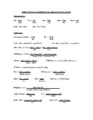
6.4 JARRING CALCULATION FORMULAE
STICKING MECHANISMS<br />
1.1 Sticking Mechanism Categories<br />
1.2 Solids Induced Pack-off<br />
1.2.1 Packing Off - First Actions<br />
a) At the first signs of the drill string torquing up and trying to pack-off, the pump strokes should be reduced by half. This will<br />
minimise pressure trapped should the hole pack-off. Excessive pressure applied to a pack-off will aggravate the situation. If the<br />
hole cleans up, return flow to the normal rate.<br />
b) If the string packs off, immediately stop the pumps and bleed down the stand<strong>pipe</strong> pressure [NB not possible with a non-ported<br />
float valve]. When bleeding pressure down from under a pack-off, control the rate so as not to "U" tube solids into the drill<br />
string in case they plug the string.<br />
c) Leave low pressure (
1.2.2 Unconsolidated formations<br />
1.2.2.1 Description<br />
An unconsolidated formation falls into the well bore because it is loosely packed<br />
with little or no bonding between particles, pebbles or boulders.<br />
Video clip of sand sloughing<br />
The collapse of the formation is caused by removing the supporting rock as the<br />
well is drilled. This is very similar to digging a hole in sand on the beach, the<br />
faster you dig the faster the hole collapses.<br />
It happens in a well bore when little or no filter cake is present. The un-bonded<br />
formation (sand, gravel, small river bed boulders etc.) cannot be supported by<br />
hydrostatic overbalance as the fluid simply flows into the formation. Sand or<br />
gravel then falls into the hole and packs off the drill string. The effect can be a<br />
gradual increase in drag over a number of metres, or can be sudden.<br />
This mechanism is normally associated with shallow formations. Examples are<br />
shallow river bed structures at about 500m in the central North Sea and in<br />
surface hole sections of land wells.<br />
This mechanism normally occurs:<br />
• While drilling shallow unconsolidated formations.<br />
1.2.2.2 Preventative Action<br />
These formations need an adequate filter cake to help stabilise the formation.<br />
Seepage loss can be minimised with fine lost circulation material. If possible,<br />
avoid excessive circulating time with the BHA opposite unconsolidated formations to reduce hydraulic erosion. Spot a gel<br />
pill before POOH. Slow down tripping speed when the BHA is opposite unconsolidated formations to avoid mechanical<br />
damage.<br />
Start and stop the pumps slowly to avoid pressure surges being applied to unconsolidated formations. Control-drill the<br />
suspected zone to allow time for the filter cake to build up, minimise annulus loading and resultant ECD’s. Use sweeps to<br />
help keep the hole clean. Be prepared for shaker, desilter and desander overloading.<br />
A method successfully used in the North Sea is to drill 10m, pull back to the top of the section and wait 10 minutes. Note<br />
any fill on bottom when returning to drill ahead. If the fill is significant then ensure the process is repeated every 10m. It<br />
may be impossible to prevent the hole collapsing. If so let the hole stabilise itself with the BHA up out of harm’s way.<br />
1.2.2.3 Rig site indications<br />
• Increase in pump pressure.<br />
• Fill on bottom.<br />
• Overpull on connections.<br />
• Shakers blinding.<br />
1.2.2.4 Freeing<br />
Follow First Actions but be aware that the pressures (i.e. 500 psi, 1500 psi) will probably not be achievable in shallow<br />
formations.<br />
1.2.3
Mobile Formations<br />
1.2.3.1 Description<br />
The mobile formation squeezes into the well bore because it is being<br />
compressed by the overburden forces. Mobile formations behave in a plastic<br />
manner, deforming under pressure. The deformation results in a decrease in<br />
the well bore size, causing problems running BHA’s, logging tools and casing.<br />
A deformation occurs because the mud weight is not sufficient to prevent the<br />
formation squeezing into the well bore.<br />
This mechanism normally occurs:<br />
• While drilling salt.<br />
1.2.3.2 Preventative Action<br />
Maintain sufficient mud weight. Select an appropriate mud system that will not<br />
aggravate the mobile formation. Plan frequent reaming/wiper trips particularly<br />
for this section of the hole. Consider bi-centre PDC bits. Slow trip speed before<br />
BHA enters the suspected area. Minimise the open hole exposure time of these<br />
formations. With mobile salts consider using a slightly under-saturated mud<br />
system to allow a controlled washout.<br />
1.2.3.3 Rig site indications<br />
• Overpull when moving up, takes weight when running in.<br />
• Sticking occurs with BHA at mobile formation depth.<br />
• Restricted circulation with BHA at mobile formation depth.<br />
1.2.3.4 Freeing<br />
Spot a fresh water pill if in a salt formation. (Consider the effect on well control and on other open hole formations ). If<br />
moving up, apply torque and jar down with maximum trip load. If moving down, jar up with maximum trip load. Torque<br />
should not be applied while jarring up.<br />
1.2.4
Fractured & Faulted Formations<br />
1.2.4.1 Description<br />
A natural fracture system in the rock can often be found near faults. Rock near<br />
faults can be broken into large or small pieces. If they are loose they can fall<br />
into the well bore and jam the string in the hole. Even if the pieces are bonded<br />
together, impacts from the BHA due to drill string vibration can cause the<br />
formation to fall into the well bore. This type of sticking is particularly unusual<br />
in that stuck <strong>pipe</strong> can occur while drilling. When this has happened in the past,<br />
the first sign of a problem has been the string torquing up and sticking. There<br />
is a risk of sticking in fractured / faulted formation when drilling through a fault<br />
and when drilling through fractured limestone formations.<br />
This mechanism can occur:<br />
• in tectonically active zones.<br />
• in prognosed fractured limestone.<br />
• as the formation is drilled.<br />
1.2.4.2 Preventative Action<br />
Minimise drill string vibration. Choose an alternative RPM or change the BHA<br />
configuration if high shock vibrations are observed. Slow the trip speed before<br />
the BHA enters a suspected fractured/faulted area.<br />
Generally, fractured formations require time to stabilise. Be prepared to spend<br />
time when initially drilling and reaming prior to making significant further<br />
progress. Circulate the hole clean before drilling ahead. Restrict tripping<br />
speed when BHA is opposite fractured formations and fault zones. Start / stop<br />
the drill string slowly to avoid pressure surges to the well bore. Anticipate<br />
reaming during trips. Ream fractured zones cautiously.<br />
1.2.4.3 Rig site indications<br />
• Hole fill on connections.<br />
• Possible losses or gains.<br />
• Fault damaged cavings at shakers.<br />
• Sticking can be instantaneous.<br />
1.2.4.4 Freeing<br />
If packed off while off bottom then follow First Actions. Otherwise JAR UP in an effort to break up formation debris. Use<br />
every effort to maintain circulation. Circulate high density viscous sweeps to clean debris. Spot acid if stuck in limestone.
1.2.5 Naturally Over-Pressured Shale Collapse<br />
1.2.5.1 Description<br />
A naturally over-pressured shale is one with a natural pore pressure greater<br />
than the normal hydrostatic pressure gradient.<br />
Naturally over-pressured shales are most commonly caused by geological<br />
phenomena such as under-compaction, naturally removed overburden (i.e.<br />
weathering) and uplift. Using insufficient mud weight in these formations will<br />
cause the hole to become unstable and collapse.<br />
This mechanism normally occurs in:<br />
• Prognosed rapid depositional shale sequences.<br />
1.2.5.2 Preventative action<br />
Ensure planned mud weight is adequate. Plan to minimise hole exposure<br />
time. Rigorous use of gas levels to detect pore pressure trends. Use of other<br />
information to predict pore pressure trends (for example Dexp ). Once the<br />
shale has been exposed do not reduce the mud weight. It may also be the<br />
case that the mud weight will need to be raised with an increase in inclination<br />
See Well bore stability Section of SP KB <strong>1997</strong> Guidelines.<br />
1.2.5.3 Rig site indications<br />
• Cavings (splintery) at shakers.<br />
• Increased torque and drag.<br />
• Gas levels, D exponent.<br />
• Circulation restricted or impossible.<br />
• Hole fill.<br />
• An increase in ROP.<br />
• Cuttings and cavings are not hydrated or mushy.<br />
1.2.5.4 Freeing<br />
Follow First Actions.<br />
1.2.6
Induced Over-Pressured Shale Collapse<br />
1.2.6.1 Description<br />
Induced over-pressure shale occurs when the shale assumes the hydrostatic<br />
pressure of the well bore fluids after a number of days exposure to that pressure.<br />
When this is followed by no increase or a reduction in hydrostatic pressure in the<br />
well bore, the shale, which now has a higher internal pressure than the well bore,<br />
collapses in a similar manner to naturally over-pressured shale.<br />
Video clip - Unstable Shale in WBM<br />
This mechanism normally occurs:<br />
• In WBM.<br />
• After a reduction in mud weight or after a long exposure time during which<br />
the mud weight was constant.<br />
• In the casing rat hole.<br />
1.2.6.2 Preventative action<br />
Non water based muds prevent inducing over-pressure in shale. Do not plan a<br />
reduction in mud weight after exposing shale. If cavings occur, utilise good hole<br />
cleaning practices. See Hole Cleaning Section<br />
1.2.6.3 Rig site indications<br />
• Cuttings / cavings show no sign of hydration.<br />
• Cavings (splintery) at shakers.<br />
• Tight hole in casing rat hole.<br />
• Increased torque and drag.<br />
• Circulating restricted or impossible.<br />
• Hole fill.<br />
1.2.6.4 Freeing<br />
Follow First Actions.<br />
1.2.7
Reactive Formations<br />
1.2.7.1 Description<br />
A water sensitive shale is drilled with less inhibition than is required. The<br />
shale absorbs the water and swells into the well bore. The reaction is ‘time<br />
dependent’, as the chemical reaction takes time to occur. However, the time<br />
can range from hours to days.<br />
This mechanism normally occurs:<br />
• When using WBM in shales and clays in young formations.<br />
• When drilling with an incorrect mud specification. Particularly, an<br />
insufficient concentration of inhibition additives in OBM and WBM such as<br />
salts (KCl, CaCL), glycol and polymer.<br />
1.2.7.2 Preventative action<br />
Use an inhibited mud system. Maintain the mud properties as planned. The<br />
addition of various salts (potassium, sodium, calcium, etc. ) will reduce the<br />
chemical attraction of the water to the shale. Various encapsulating (coating)<br />
polymers can be added to WBM mud to reduce water contact with the shale.<br />
Monitoring mud properties is the key to detection of this problem. Open hole<br />
time in shale should be minimised. Regular wiper trips or reaming trips may<br />
help if shales begin to swell. The frequency should be based on exposure<br />
time or warning signs of reactive shales. Ensure hole cleaning is adequate to<br />
clean excess formation i.e. clay balls, low gravity solids etc.<br />
1.2.7.3 Rig site indications<br />
• Hydrated or mushy cavings.<br />
• Shakers screens blind off, clay balls form.<br />
• Increase in LGS, filter cake thickness, PV, YP, MBT.<br />
• An increase or fluctuations in pump pressure.<br />
• Generally occurs while POOH.<br />
• Circulation is impossible or highly restricted.<br />
1.2.7.4 Freeing<br />
POH slowly to prevent swabbing. See First Actions.<br />
1.2.8
Hole Cleaning<br />
1.2.8.1 Description<br />
In deviated wells cuttings and cavings settle to the low side of the<br />
hole and form layers called solids beds or cuttings beds. The BHA<br />
becomes stuck in the solids bed.<br />
OR<br />
Cuttings and cavings slide down the annulus when the pumps are<br />
turned off and pack-off the drill string. Avalanching can also occur<br />
while the pumps are on.<br />
Good hole cleaning means removal of sufficient solids from the well<br />
bore to allow the reasonably unhindered passage of the drill string<br />
and the casing.<br />
There are several main reasons for solids not being cleaned out of<br />
the well bore.<br />
These are:<br />
• A low annular flow rate.<br />
• Inappropriate mud properties.<br />
• Insufficient circulation time.<br />
• Inadequate mechanical agitation.<br />
If any of the above are missing good hole cleaning will be very<br />
unlikely.<br />
In 40-65 degree wells the cuttings bed will slide down the low side of<br />
the hole. This can happen while pumping, not just when the pumps<br />
are off. In highly deviated wells of 65 degrees or more cuttings<br />
settle very quickly in spite of high flow rates. This is known as<br />
avalanching.<br />
A cuttings bed of 10% of the hole diameter (1.75 inches in 17.5 inch hole) looks harmless enough. Add a drill string and<br />
the situation looks very different.<br />
Cuttings beds can also increase drag in the well and cause problems with applying WOB in horizontal holes.<br />
Preventative Action<br />
• Maximise the annular velocity.<br />
- Consider the use of a third mud pump.<br />
- Consider using larger drill <strong>pipe</strong>.<br />
• Ensure circulation times are adequate.<br />
- Consult the hole cleaning charts for confirmation.<br />
- Monitor the cuttings returns at the shakers.<br />
• Maximise mechanical agitation of cuttings beds.<br />
- Rotation.<br />
- Reciprocation.<br />
• Optimise mud properties.<br />
- increase YP in near vertical wells.<br />
1.2.8.2 Rig site indications<br />
• Overpulls increasing while POOH from TD in deviated hole (7-10 stands).<br />
• Erratic pump pressure.<br />
• Poor weight transfer to bit.<br />
• Difficulty orienting toolface.<br />
• Absence of returns at shakers.<br />
• Presence of re-ground cuttings (LGS).<br />
• Overpulls inside casing.<br />
1.2.8.3 Freeing<br />
See First Actions<br />
Refer to Hole Cleaning section for more information.
1.2.9 Tectonically Stressed Formations<br />
1.2.9.1 Description<br />
Well bore instability is caused when highly stressed formations are drilled and<br />
there exists a significant difference between the near well bore stress and the<br />
restraining pressure provided by the drilling fluid density.<br />
Tectonic stresses build up in areas where rock is being compressed or<br />
stretched due to movement of the earth’s crust. The rock in these areas is<br />
being buckled by the pressure of moving tectonic plates.<br />
When a hole is drilled in an area of high tectonic stresses the rock around the<br />
well bore will collapse into the well bore and produce splintery cavings similar<br />
to those produced by over-pressured shale. In the tectonic stress case the<br />
hydrostatic pressure required to stabilise the well bore may be much higher<br />
than the fracture pressure of the other exposed formations<br />
This mechanism usually occurs:<br />
• in or near mountainous regions.<br />
1.2.9.2 Preventative action<br />
Plan to case off these formations as quickly as possible. Maintain mud weight<br />
within planned mud weight window. Well bore instability shows itself as a hole<br />
cleaning problem. If possible drill these formations in smaller hole sizes. This<br />
will minimise the impact of a hole cleaning problem. Ensure that the circulation<br />
system is capable of handling the additional volume of cavings often<br />
associated with this mechanism. If hole problems do occur, Ref Hole Cleaning section. Use offset data to establish<br />
optimum inclination and azimuth as these are key factors in reducing the extent of the problem. Ref Wellbore Stability<br />
section in <strong>1997</strong> Guidelines.<br />
1.2.9.3 Rig site indicators<br />
• Pack-offs and bridges may occur.<br />
• Cavings at the shakers (splintery).<br />
• Increase torque and drag.<br />
• If stuck, circulation is likely to be impaired or non-existent.<br />
• Increase in volume of returns at the shakers relative to the hole volume drilled.<br />
1.2.9.4 Freeing<br />
See First Actions<br />
1.3
1.3.1.1 Description<br />
Differential Sticking<br />
Differential sticking occurs when the drill string is held against the well bore by a<br />
force. This force is created by the imbalance of the hydrostatic pressure in the<br />
well bore and the pore pressure of a permeable formation. When the hydrostatic<br />
pressure is greater than the pore pressure the difference is called the<br />
overbalance. The resultant force of the overbalance acting on an area of drill<br />
string is the force that sticks the string.<br />
This mechanism normally occurs:<br />
1) With a stationary or very slow moving string.<br />
2) When contact exists between the drill string and well bore.<br />
3) When an overbalance is present.<br />
4) Across a permeable formation.<br />
5) In a thick filter cake.<br />
1.3.1.2 Preventative Action<br />
Any action taken to reduce or eliminate one or more of the above causes will<br />
reduce the risk of differential sticking.<br />
Well design<br />
Where possible design casing setting depths to minimise overbalance across<br />
potential sticking zones, i.e. design for minimum overbalance. Limit mud weight to the minimum required for hole stability<br />
and well control.<br />
Mud<br />
Use OBM where possible. Keep fluid loss to a minimum.<br />
Maintain a low concentration of LGS. Keep gels low.<br />
Stationary string<br />
Hole Size (inches) Recommended % LGS<br />
17.5 10-15<br />
12.25 8-10<br />
8.5 5-8<br />
6 5-8<br />
KEEP THE STRING MOVING. Pre-plan to minimize the down time for operations that require the string to remain static<br />
(surveys, minor repairs, etc .). Consider rotating the string during drilling and tripping connections while BHA is opposite<br />
high risk sticking zones.<br />
Well bore contact<br />
Minimise BHA length when possible. Maximise BHA stand-off. Use spiral drill collars.<br />
Rig team awareness<br />
The rig team can be made aware of the depth of permeable formations and the estimated overbalance in those zones.<br />
1.3.1.3 Rig site indications<br />
• Overpulls on connections and after surveys<br />
• No string movement<br />
• Full unrestricted circulation<br />
• Losses<br />
• High overbalance<br />
• Permeable formation exposed in open hole<br />
1.3.1.4
Freeing<br />
First Actions in the event of Differential Sticking<br />
1. Establish that Differential Sticking is the mechanism, i.e, stuck after a connection or survey with full<br />
unrestricted circulation across a permeable formation Sand, ( Dolomite and possibly Limestone ).<br />
2. Initially circulate at the maximum allowable rate. This is to attempt to erode the filter cake.<br />
3. Slump the string while holding 50% of make-up torque of surface <strong>pipe</strong> (unless mixed string of <strong>pipe</strong> is being<br />
used). Use an action similar to what would be used with a bumper sub - see note below.<br />
4. Pick up to just above the up weight and perform step 2 again.<br />
5. Repeat 2. & 3. Increasing to 100% make-up torque until string is freed or until preparations have been made<br />
to:<br />
either - spot a releasing pill<br />
or<br />
- conduct “U" tube operations.<br />
1.4
Mechanical & Well Bore Geometry<br />
1.4.1 Other <strong>Stuck</strong> Pipe Types - First Action<br />
Guidelines for freeing stuck <strong>pipe</strong> other than Pack-offs and Differential sticking.<br />
a) Ensure circulation is maintained.<br />
b) If the string became stuck while moving up, apply ( torque ) jar down.<br />
c) If the string became stuck while moving down, do not apply torque and Jar up.<br />
d) Jarring operations should start with light loading (50k lbs) and then systematically increased to maximum load over a one hour<br />
period. Stop or reduce circulation when; a) cocking the jars to fire up and b) jarring down. Pump pressure will increase jar<br />
blow when jarring up, so full circulation is beneficial ( beware of maximum load at the jar - see jarring section of this manual<br />
).<br />
e) If jarring is unsuccessful consider acid pills, if conditions permit. Details can be found in the Best Practices chapter for<br />
running acid pills<br />
1.4.2
Key Seating<br />
1.4.2.1 Description<br />
Key seating is caused by the drill <strong>pipe</strong> rotating against the bore hole wall<br />
at the same point and wearing a groove or key seat in the wall. When<br />
the drill string is tripped, the tool joints or the BHA are pulled into the key<br />
seat and become jammed. Key seating can also occur at the casing<br />
shoe if a groove is worn in the casing.<br />
This mechanism normally occurs:<br />
• At abrupt changes in angle or direction in medium-soft to mediumhard<br />
formation.<br />
• Where high side wall forces and string rotation exist.<br />
• While pulling out of the hole.<br />
• After long drilling hours with no wiper trips through the dogleg section.<br />
1.4.2.2 Preventative Action<br />
Minimise dogleg severity. Perform reaming and/or wiper trips if a dogleg<br />
is present. Consider running string reamers or a key seat wiper if a key<br />
seat is likely to be a problem.<br />
1.4.2.3 Rig Site Indications<br />
• Occurs only while POOH.<br />
• Sudden overpull as BHA reaches dogleg depth.<br />
• Unrestricted circulation.<br />
• Free string movement below key seat depth possible if not already stuck in key seat.<br />
• Cyclic overpull at tool joint intervals on trips.<br />
1.4.2.4 Freeing<br />
If possible, apply torque and jar down with maximum trip load. Back ream out of the hole. If present use key seat wiper.<br />
1.4.3
Undergauge Hole<br />
1.4.3.1 Description<br />
Drilling hard abrasive rock wears the bit and the stabiliser gauge and results<br />
in a smaller than gauge hole. When a subsequent in-gauge bit is run, it<br />
encounters resistance due to the undergauge section of hole. If the string is<br />
run into the hole quickly without reaming, the bit can jam in the undergauge<br />
hole section.<br />
This mechanism normally occurs:<br />
• After running a new bit.<br />
• After coring<br />
• When a PDC bit is run after a roller cone bit<br />
• When drilling abrasive formations<br />
Other sticking mechanisms may give similar effects particularly mobile<br />
formations.<br />
Core heads are often slightly smaller than bit sizes and cored sections<br />
should be reamed when running in with a bit to drill ahead. Failure to ream<br />
in to the hole can result in the bit jamming in the undergauge section of<br />
cored hole.<br />
1.4.3.2 Preventative Action<br />
Use suitably gauge-protected bits and stabilisers. Consider the use of roller<br />
reamers. Always gauge all BHA components both when running in and<br />
pulling out of the hole. Ream suspected undergauge sections. Slow the trip<br />
speed down before the BHA enters an undergauge zone.<br />
1.4.3.3 Rig site indications<br />
• Pulled bit or stabilisers are undergauge.<br />
• Occurs only when RIH.<br />
• Sudden setdown weight.<br />
• Circulation is unrestricted or slightly restricted.<br />
• Bit stuck near the bottom of the hole or at the top of a cored section.<br />
1.4.3.4 Freeing<br />
Jar up with maximum trip load. Do not jar down. Consider the use of an acid pill. Consider applying torque as a last<br />
resort.<br />
1.4.4
Ledges and Doglegs<br />
1.4.4.1 Description<br />
Ledge: The well bore passes through rock of varying types and ledges<br />
develop at the interfaces between layers of differing hardness.<br />
Doglegs: While drilling a well bore, the characteristics of the rock cause<br />
the bit to be deflected and can result in a change in direction. Likewise<br />
when drilling with a directional BHA, sudden changes in angle can cause<br />
a kink in the well bore direction. Sharp deviations in wellbore direction<br />
are called doglegs.<br />
This mechanism usually occurs:<br />
• When an unsuitable BHA is run.<br />
• After a change in BHA.<br />
• Prognosed hard soft interbedded formations.<br />
• Prognosed fractured / faulted formations.<br />
• After direction changes.<br />
• While POOH.<br />
1.4.4.2 Preventative Action<br />
Ledging will be reduced by running a packed hole assembly. Minimise<br />
direction changes in the well bore. Minimise BHA configuration changes<br />
when in formations likely to produce ledges. Consider reaming trips.<br />
Make a log of depths of ledges and other anomalies.<br />
It can help to get a large scale printout from the mud loggers and to<br />
draw a scale BHA on a separate piece of paper. The paper BHA can<br />
be positioned at the depth of any overpulls and it is easy to see if any of the stabilisers are hanging up at the<br />
same point. By using this technique it is simple to keep track of multiple problem zones and to communicate<br />
expected problem depths clearly to the driller.<br />
Survey with sufficient frequency. Increasing the well bore survey frequency will:<br />
-assist in evaluating/reducing well bore tortuosity.<br />
-reduce the number of BHA changes.<br />
Slow trip speeds before BHA enters the suspected ledge zone or dog leg. Avoid prolonged circulation across soft<br />
interbedded formations. Limit initial setdown weight to less than 50% of down drag to minimise momentum effects when<br />
running into a tight zone. Do not start angle building operations too close to the shoe (start at least 30m below old hole<br />
TD).<br />
1.4.4.3 Rig site indications<br />
• Sudden erratic overpull or setdown.<br />
• Problems are at fixed depths.<br />
• Full circulation is possible.<br />
1.4.4.4 Freeing<br />
If moving up when sticking occurred, apply torque and jar down with maximum trip load. If moving down, jar up with<br />
maximum trip load. Do not apply torque.<br />
If able to, backream or ream very slowly past problem as rotation will assist the stabilisers and/or other tools to roll past<br />
the ledge.<br />
1.4.5
Junk<br />
1.4.5.1 Description<br />
Debris that has fallen into the hole from surface or from downhole equipment,<br />
which falls down the well bore and jams the drill string.<br />
This mechanism usually occurs:<br />
• Due to poor housekeeping on the rig floor.<br />
• The hole cover not being installed.<br />
• Downhole equipment failure.<br />
1.4.5.2 Preventative Action<br />
Encourage good housekeeping on the rig floor and regular inspection of<br />
handling equipment. Keep the hole covered at all times. Inspect downhole<br />
equipment before it is run in the hole and again as it is being run through the<br />
rotary table. Inspect slip and tong dies regularly. Install drill string wiper<br />
rubber as quickly as possible.<br />
1.4.5.3 Rig site indications<br />
• Repair/maintenance work recently performed on the rig floor.<br />
• Missing hand tools / equipment.<br />
• Circulation unrestricted.<br />
• Metal shavings at shaker.<br />
• Sudden erratic torque.<br />
• Inability to make hole.<br />
1.4.5.4 Freeing<br />
See First Actions<br />
1.4.6
Collapsed Casing / Tubing<br />
1.4.6.1 Description<br />
Casing collapses either if pressure conditions exceed its original rated<br />
collapse pressure or the original collapse pressure rating of the casing is no<br />
longer valid due to casing wear and/or corrosion. Casing wear due to friction<br />
or corrosion decreases the effective collapse pressure rating of the casing,<br />
through decreased wall thickness. Collapse is often discovered when the<br />
BHA is run into the hole and hangs up inside the casing.<br />
This mechanism can occur when:<br />
• The collapse pressure of the casing is exceeded during a pressure test<br />
where an annulus leak is occurring. The collapse pressure of the casing<br />
may be less than expected, due to casing wear.<br />
• The casing fluid is evacuated, causing the casing to collapse.<br />
• The casing is buckled due to aggressive running procedures.<br />
1.4.6.2 Preventative measures<br />
Avoid casing wear, refer to casing wear guidelines. Good cementing<br />
practices should be used. Cement to surface or as high as possible. Use<br />
corrosion inhibitors in fluids.<br />
1.4.6.3 Rig site indicators<br />
• BHA hangs up when RIH.<br />
• Caliper log shows collapsed casing.<br />
1.4.6.4 Freeing<br />
Jar out of the hole if possible.<br />
1.4.7
Cement Blocks<br />
1.4.7.1 Description<br />
The drill string becomes jammed in the hole by cement blocks falling around<br />
the string.<br />
This mechanism normally occurs when :<br />
• Hard cement becomes unstable around the casing shoe, open hole<br />
squeeze plugs and kick-off plugs.<br />
1.4.7.2 Preventative Action<br />
Allow sufficient curing time for cement before attempting to kick off or drill<br />
out. Ream casing shoe and open hole plugs thoroughly before drilling ahead.<br />
Limit casing rathole length to minimise a source of cement blocks. Slow the<br />
trip speed down before the BHA enters the casing shoe or the plug depth.<br />
Use of fibre additives to the cement can increase its integrity. Maintain<br />
sufficient distance between the paths of platform wells to reduce the<br />
possibility of cement blocks from adjacent well bores.<br />
1.4.7.3 Rig site indications<br />
• Circulation unrestricted.<br />
• Cement fragments.<br />
• Rotation and downward movement may be possible.<br />
• Erratic torque.<br />
1.4.7.4 Freeing<br />
See First Actions<br />
1.4.8
Green Cement<br />
1.4.8.1 Description<br />
When the drill string is inadvertently run into cement, the cement can flash<br />
set. The top of the cement may be higher than prognosed. The increase in<br />
pressure generated by the surge of the BHA causes the cement to flash set.<br />
Circulation is attempted with the bottom of the drill string in soft cement.<br />
The increase in pressure causes the cement to flash set.<br />
A high penetration rate is used when cleaning out recently set cement,<br />
below which is un-set cement which flash sets.<br />
This mechanism normally occurs:<br />
• While running into the hole to dress off cement<br />
1.4.8.2 Preventative Action<br />
Do not rely solely on surface samples. Know the cement setting time, but<br />
do not assume it will be set when you trip in to the hole. Know the<br />
calculated top of cement (TOC) before tripping in hole but always expect it<br />
to be higher. Do not rely on the weight indicator to find the top of the<br />
cement. If the cement is not set you may not see any indication on the<br />
weight indicator when you run into it.<br />
In large hole sizes begin washing down two stands above the theoretical top<br />
of the cement. Consider starting to ‘wash through’ 3-4 stands above the<br />
theoretical cement top in small hole sizes. If set down weight is observed<br />
when tripping in hole after a cement operation, pull back 2 stands before<br />
attempting circulation. Control drill when cleaning out soft cement.<br />
Consider pre-treating the mud system with chemicals prior to drilling out the<br />
cement.<br />
1.4.8.3 Rig site indications<br />
• Increase in pump pressure leading to inability to circulate.<br />
• Loss of string weight.<br />
• Sudden decrease in torque.<br />
• Green cement in mud returns, discoloration of mud.<br />
1.4.8.4 Freeing<br />
Bleed off any trapped pump pressure. Jar up with maximum trip load. Attempt to establish circulation.<br />
2.
TECHNICAL ISSUES
2.1 Hole Cleaning<br />
2.1.1 Monitoring Cuttings Returns at the Shakers<br />
The practice of monitoring the volume rate of cuttings and cavings being circulated out of the hole at the shakers has<br />
proven a worthwhile exercise in different areas of the world. In Vietnam this practice is maintained to monitor hole<br />
cleaning efficiency. In Wytch Farm in the UK, hole cleaning is being monitored in an attempt to eliminate related torque<br />
problems in ERD (extended reach ) wells. In Colombia the volume rate of cuttings and cavings is monitored for several<br />
reasons:<br />
1. To establish hole cleaning efficiency.<br />
2. As a warning tool when the well bore is loaded and a potential pack-off situation is occurring.<br />
3. To gain better understanding of well bore behaviour. (for example: failure cycles, caliper / removed volume relationship<br />
).<br />
4. In addition it gives a very clear indication that the hole is being cleaned up after a pack-off has occurred and has been<br />
freed.<br />
Discussion<br />
It is recommended that rigs should now have a procedure in place for monitoring solids volume rate. The Mud Loggers<br />
should be regularly monitoring the volume rate of cuttings and cavings. This information should be passed on to both the<br />
rig floor and the BP Rep.<br />
The current method used in a number of locations is to measure, every hour, the time taken to fill a 5 gallon bucket with<br />
solids coming over the shakers.<br />
After freeing the string, once the pack-off material has been circulated out of the hole, the solids rate at the shakers will<br />
often increase by 150 %. For a particular operation and hole size, normal trends for the volumetric flow rate can be<br />
established by regular observation (the 5 gallon bucket method ) and used as a hole problem warning trend.<br />
It is a theory that most pack-offs occur immediately after a connection while backreaming. From the Cupiagua well data in<br />
Colombia this does not appear to be true, however the majority do occur within the first single after a connection. It is<br />
obviously important that the BHA should be circulated clear prior to stopping the pumps.<br />
The possibility of developing a more accurate and automated measuring system has been investigated, (possibly using<br />
load cells or monitoring shaker current ). The summary of this study can be found in this manual or in the <strong>Stuck</strong> <strong>pipe</strong><br />
knowledge base in BP Reports section report number 20.<br />
2.1.1.1 Cuttings Catchers<br />
The following text is the Executive Summary from the Cuttings Catcher Study;<br />
Cuttings Catcher Study Summary, by Colin Bowes.<br />
The quantity of cuttings coming over the shakers at surface compared to the theoretical volume cut by the bit can give<br />
important information on hole cleaning efficiency and hole stability. This can provide early warning signals of worsening<br />
hole conditions.<br />
There are currently three existing designs of automated machinery which measure the quantity of cuttings coming over the<br />
shakers and which have been recently field tested. Two mud logging companies are also field testing their own prototype<br />
cuttings catcher designs.<br />
All field trials have encountered equipment problems. Assurances have been given by all the manufacturers that these<br />
problems can be ironed out. However, there is no cuttings catcher on the market today which is operationally fit for<br />
purpose.<br />
The majority of data from the field trials has been erroneous. No field trial has demonstrated any real time utilisation of<br />
the data. Post well analysis of the data has met with limited success, e.g. only two from the seven known field trials has<br />
provided 'reasonable' artificially calculated calipers.<br />
A majority remain sceptical concerning the application of the data, both real time and post well, primarily due to several<br />
assumptions and corrections which are necessary to convert a mass of cuttings at surface to a volume of drilled hole. The<br />
theory appears to have received limited attention from the manufacturers or other oil companies.<br />
As a stand-alone hole cleaning and hole stability monitoring device the cuttings catcher has severe limitations. Interfacing<br />
the cuttings catcher information with the information from the mud logging unit has the potential to provide an effective<br />
hole cleaning and hole stability monitoring system.<br />
Combining the cuttings catcher information with the mud logging unit information, a number of possible uses and<br />
applications have been identified:<br />
- To provide a stuck <strong>pipe</strong> prevention tool.<br />
- To provide the drill crew with timely information regarding hole cleaning efficiency.
- To optimise drilling fluid properties and pump rates.<br />
- To produce an artificially derived calliper.<br />
- To provide continuous measurement of the cave-in rate while tripping / reaming.<br />
These applications have yet to be fully proven. Due to the number of corrections and assumptions, and the labour<br />
intensive management of the cuttings catcher data, real time quantitative information can not be relied upon, (i. e., the<br />
artificial calliper ). Only real time qualitative trend information can be used to predict hole cleaning efficiency and stability.<br />
Further field trial experience is required to both develop and improve the cuttings catcher equipment and theory.<br />
2.1.2 Hole Cleaning<br />
Removal of cuttings from the well bore is an essential part of the drilling operation. Efficient hole cleaning must be<br />
maintained in all wells. Failure to effectively transport the cuttings can result in a number of drilling problems including:<br />
• Excessive overpull on trips.<br />
• High rotary torque.<br />
• <strong>Stuck</strong> <strong>pipe</strong>.<br />
• Hole pack-off.<br />
• Formation break down.<br />
• Slow ROP.<br />
• Lost Circulation.<br />
The rig team have control over a number of parameters that assist hole cleaning, namely pumping hole cleaning pills,<br />
methods used to pull out of the hole, choice of reaming speeds, choice of ROP, flowrate, movement of string while<br />
circulating, etc. Of these the annular flowrate is very important.<br />
Hole cleaning is often more of an issue in a gauge hole than it is in an over gauge hole. When drilling a 17.5” hole using a<br />
gyp/ligno mud system with frequent dumping and diluting the diameter of the hole can be as much as 24 inches. If a 10<br />
inch cuttings bed exists the BHA will pass this with only minimum extra drag. If a highly inhibitive mud system is being<br />
used for drilling shale in a 12.25” hole, the diameter of the hole is likely to be 12.25”. A 1.5” cuttings bed can cause severe<br />
overpull problems in this hole if it is not dealt with correctly.<br />
All of these are potential problems for both near vertical (less than 30 deviation) and ERD wells. Generally hole cleaning<br />
rarely presents a problem in near vertical wells. The problems listed above are common on highly deviated wells.<br />
Successful hole cleaning relies upon integrating optimum mud properties with best drilling practices. When difficulties are<br />
encountered it is essential to understand the nature and causes of the problem. This allows options to be focused on<br />
determining the most appropriate actions.<br />
2.1.3 General Factors Effecting Hole Cleaning<br />
There is a large number of drilling parameters which influence the hole cleaning process. The driller has a direct control on<br />
some parameters, others are pre-determined by the constraints of the drilling operation.<br />
Cuttings Transport<br />
In holes inclined at less than 30 , the cuttings are effectively suspended by the fluid shear and cuttings beds do not form.<br />
• Conventional transport calculations based on vertical slip velocities are applicable to these wells. Generally for these<br />
shallow angled wells, annular velocity requirements are typically 20-30% in excess of vertical wells.<br />
In deviated wells, those above 30 , cuttings tend to settle on the low side wall and form cuttings beds. Cuttings fall to the<br />
low side of the hole and are transported along the low side of the hole as cuttings beds. These beds often form into dunes<br />
if string rotation is not present. These cuttings beds can slide back down the well, causing the annulus to pack-off, this is<br />
referred to as avalanching. Cuttings which form on the low side of the hole can either move en-masse as a sliding bed or<br />
alternatively may be transported at the cuttings bed / mud interface as ripples or dunes. The problem is they can move in<br />
either direction even when the pumps are on.<br />
Rheology<br />
The effect of mud rheology on hole cleaning depends on the annular flow regime.<br />
• When laminar flow exists, increasing the mud viscosity will improve hole cleaning. (This is particularly effective if the<br />
low shear rheology and YP/PV ratio are high.)<br />
• When turbulent flow exists, reducing the mud viscosity will help remove cuttings.<br />
Yield Stress<br />
This is a measure of the low shear properties of the mud. It is determined from the 6 and 3 rpm readings of a<br />
conventional Fann viscometer, [ YS=2x(Fann 6 - Fann 3) ].<br />
Yield stress controls the size of cuttings which can be suspended by the flowing mud (dynamic suspension ). The dynamic<br />
suspension will be affected by cuttings' size and mud density. In practice the optimum level required is best established<br />
based on field data and experience.
Flow Rate<br />
The mud flow rate provides a lifting force on cuttings to carry them out of the well. In highly deviated wells, mud flow rate<br />
combined with mechanical agitation are the most important factors for hole cleaning. For vertical wells the rate of cuttings'<br />
removal increases with increasing annular velocity and/or increased rheological properties.<br />
AV ( ft / min) =<br />
24.<br />
51×<br />
GPM<br />
2 2<br />
( Holesize − drill<strong>pipe</strong>size )<br />
Hole Geometry<br />
Hole diameter has a very significant effect on annular velocity. Reducing hole diameter from 17½” to 16” will increase<br />
annular velocity by 18%.<br />
Mud Weight<br />
Mud weight influences hole cleaning by affecting the buoyancy of the drilled cuttings. As mud weight increases, the<br />
cuttings will tend to "float" out of the well making hole cleaning easier. In practice the mud weight window will be<br />
constrained by drilling factors other than hole cleaning (well bore stability, ECD, differential sticking, etc.).<br />
Cuttings Properties<br />
Hole cleaning is dependent upon both cuttings' size and density. Increasing size and density both tend to increase the<br />
cuttings' slip velocity. This makes transport more difficult. The effects of higher slip velocity can be combated by an<br />
appropriate increase in yield stress and mud gel. In extreme circumstances bit selection can be used to generate smaller<br />
cuttings and, hence, reduce slip velocity. However, if cuttings get ground up into fines they can be hard to remove from a<br />
deviated section of well bore.<br />
Rate of Penetration<br />
An increase in penetration rate results in a higher cuttings' concentration in the annulus. This will lead to a higher effective<br />
mud density in the annulus and higher circulating pressures, which may in turn limit flow rates.<br />
Drill String Rotation<br />
In deviated wells high drill <strong>pipe</strong> rotation speeds provide an effective means of mechanically disturbing cuttings beds and<br />
lifting them from the low side into the main mud flow for removal. Rotary speeds of 150 rpm have been shown<br />
experimentally to dramatically increase the removal of cuttings beds.<br />
Drill string rotation has little effect on hole cleaning in near vertical wells. In the smaller hole sections of HTHP wells,<br />
string rotation can cause an increase in pump pressure/ECD.<br />
2.1.4 Rig Site Monitoring<br />
There are a number of rig-site indicators that should be used to monitor the hole condition and allow preventative action to<br />
be chosen. These should normally be examined for trends and sudden departures from the trend rather than absolute<br />
values.<br />
• The shape and size of the cuttings coming over the shaker should be regularly monitored. Small rounded cuttings<br />
indicate that cuttings have been spending extended periods downhole being reground by the BHA. These are often<br />
evident coming over the bottom shaker screen. These fines can be of significant volume if regrinding of shale is<br />
occurring in an inhibitive mud system.<br />
• The cuttings return rate at the shakers should also be measured and compared with the volume predicted from ROP.<br />
Simple devices are available to automate the measurement. However, it is difficult to measure the quantity of fines<br />
returning.<br />
• Torque and drag can be used to determine whether cuttings beds are adding to the well bore friction. Simulations<br />
should be conducted in advance using the Drill String Simulator (DSS -- a part of the DEAP program). Deviations from<br />
the normal trend line can be indicative of cuttings bed forming.<br />
• Erratic signal in torque or stand <strong>pipe</strong> pressure can also be an early warning of cuttings beds.<br />
2.1.5 Vertical and Near Vertical Wells<br />
Rheology plays a very important role in transporting cuttings in vertical and near-vertical holes. Large diameter holes, in<br />
particular, cannot be cleaned by velocity alone. However, assuming that the mud has the correct rheology, hole cleaning<br />
on these wells is not normally a problem. The mud annular velocity is generally far greater than the cuttings’ slip velocity<br />
and so the cuttings are carried out of the hole. To ensure that a low slip velocity is achieved, these wells are usually drilled<br />
with viscous, high yield point muds.<br />
Hole Cleaning in Near Vertical Wells - Guidelines<br />
1. Select mud properties to provide optimum hole cleaning whilst drilling. The specific properties will depend upon<br />
available pump rate. In all cases mud rheology should be maintained at a level that will reduce slip velocity to
acceptable levels. Specific requirements for annular velocity compared with cuttings slip velocity can be obtained<br />
within DEAP.<br />
2. Poor hole cleaning will result in high cuttings loading in the annulus. When circulation is stopped these cuttings can<br />
fall back and pack-off the BHA. When packing-off occurs this means the flow rate is too low or the well has not been<br />
circulated for sufficient time (assuming that the above criteria for mud properties has been met).<br />
3. Circulate the hole thoroughly prior to tripping -- A single bottoms-up is not sufficient. The minimum<br />
recommended volume for vertical wells is 1.3 x bottoms-up (1.5 for holes > 8 1 /2"). Monitor the shakers to ensure the<br />
cuttings return rate is reduced to an acceptable background level prior to commencing tripping.<br />
4. Limit use of high viscosity pills to supplement hole cleaning. Rather adjust the properties of the active mud in<br />
circulation to provide optimum cleaning capacity. High weight pills should not be used in vertical wells.<br />
5. For vertical holes reciprocate rather than rotate the <strong>pipe</strong> during circulation prior to tripping -- this helps remove<br />
cuttings from stagnant zones near the well bore wall.<br />
6. Pulling through tight spots is permitted provided the <strong>pipe</strong> is free going down. Agree a maximum allowable overpull in<br />
advance with the BP Rep / Drilling Superintendent. Do not go immediately to the maximum overpull, but work up<br />
progressively, ensuring that the <strong>pipe</strong> is free to go down on every occasion.<br />
7. Stop and circulate the hole clean if overpulls become excessive.<br />
8. Avoid precautionary backreaming, only backream when essential.<br />
9. Understand the nature and causes of any problems encountered on tripping.<br />
2.1.6 High Angle, Extended-Reach Wells<br />
Much of the information given above relating to hole cleaning in near vertical wells is relevant to ERD wells. However, it<br />
is far more difficult to maintain clean hole in a deviated well. The guidelines given below are based on the conclusions<br />
derived from both laboratory and field data:<br />
2.1.6.1 Characteristics of Cuttings Beds<br />
65-90 degree wells.<br />
In wells of this inclination the cuttings bed is stable. It is a danger mainly due to the effect it has when the BHA is pulled<br />
through it. Even a small cuttings bed of 10% volume can result in stuck <strong>pipe</strong> if the appropriate procedures are not<br />
followed while pulling out of the hole. One of the dangers of all high angle wells is that they all contain a section of 40 - 65<br />
degree hole (see below).<br />
40-65 degree wells.<br />
This is the area where the cuttings’ bed comes alive. It may settle and be reasonably static but it may also be completely<br />
unstable and prone to avalanche even when the pumps are on and the flow rate is very high.<br />
Avalanching is a term applied to cuttings beds when they slide down the well bore in exactly the same way as snow slides<br />
down a hillside.<br />
2.1.6.2 Hole Cleaning in Deviated Wells - Guidelines<br />
Flow Rate<br />
The single most important factor relating to hole cleaning in deviated wells is annular velocity. Annular velocity is<br />
determined by hole size, combined drill <strong>pipe</strong> / BHA size and most significantly flowrate. During directional drilling<br />
operations, drilled cuttings will settle on the low side of the hole and form a stationary bed if the annular fluid velocity is<br />
inadequate. The critical flow rate (CFR) required to prevent cuttings bed formation can be determined from the BP Hole<br />
Cleaning Model. When planning a well it is important that mud pumps of adequate size and capacity are selected. This<br />
will allow the required minimum flowrate to be achieved. Typically, few hole cleaning problems exist in vertical or<br />
horizontal sections. Most problems associated with hole cleaning seen deviated wells occur in the 50 - 60 degrees<br />
section. Here cuttings beds avalanche down the hole under gravity and cause sticking problems. The BP Hole Cleaning<br />
Model should be used in the planning of all wells and in particular Extended Reach applications.<br />
Typical flow rates to aim for in ERD wells are as follows:
HOLE SIZE<br />
TYPICAL FLOW RATES<br />
17 1 /2" 1100 gpm minimum<br />
Some rigs achieve 1250 - 1400 gpm<br />
12 1 /4" Aim for 1100 gpm (although 800 - 1000 gpm is typically<br />
achieved )<br />
If 1000 gpm is not achievable, ensure tripping<br />
procedures are in place for poorly cleaned hole.<br />
8 1 /2" Aim for 500 gpm<br />
Table 1<br />
Mud Rheology<br />
Experience has shown that good mud rheology is extremely important to hole cleaning when drilling a high angle well.<br />
Studies show that the effects of increasing rhelogy and annular flow regime are mutually dependent.<br />
• In the laminar regime, increasing mud YP will improve hole cleaning. This is particularly effective if the YP/PV ratio is<br />
high. {However, a more viscous mud has difficulty in lifting the cuttings off the bottom in a high angle well }.<br />
• In the turbulent regime, however, reducing mud viscosity will help in removing cuttings. {However, reducing the<br />
viscosity will increase the likelihood of avalanching in a deviated well.}<br />
Therefore the mud rheology should be designed to avoid the transitional flow regime and the importance of mechanical<br />
agitation should be recognised. For hole sizes above 8½", the annular flow is laminar under most circumstances.<br />
Therefore it is desirable to specify a minimum YP/PV ratio. In practice the optimum level required is best established<br />
based on field data and experience.<br />
Selection of Flow Regime<br />
When correctly designed both laminar and turbulent flow regimes will effectively clean a deviated well. Increasing the YP<br />
of a fluid in laminar flow will improve hole cleaning of suspended cuttings as will a reduction of the YP of a fluid in<br />
turbulent flow decrease cuttings bed thickness. It is important that one or the other regime is selected and that the<br />
transition zone between the two is avoided, as it is the worst region in which to operate with intermediate mud properties.<br />
However, if laminar flow is chosen, string movement must be used to effectively lift the cuttings from the low side of the<br />
hole.<br />
Generally, viscous fluids in laminar flow are preferred because:<br />
• It is possible to achieve higher cleaning capacity (rheology factor).<br />
• Viscous fluids give better transport in the near-vertical sections.<br />
• Viscous mud has better suspension characteristics when circulation is stopped.<br />
• It is difficult in practice to achieve "turbulent flow" except for small hole sizes.<br />
Turbulent flow effectively prevents the formation of cuttings beds on the low side of highly deviated wells when the pumps<br />
are on. When the pumps are turned off the cuttings can rapidly fall to the low side of the hole and avalanche back down.<br />
Turbulent regimes should not be used in friable, non competent formations. Subsequent wash-out of the rock will reduce<br />
annular velocities to a point where laminar flow will develop in a fluid with properties specifically designed for turbulence.<br />
Cuttings bed formation will inevitably follow. Effectively the same process can occur as the fluid, designed for turbulence<br />
in small diameter hole, enters larger diameters further up the hole. All fluids designed for turbulence must have, as a<br />
minimum, sufficient suspension characteristics and carrying capacity to clean these larger hole (casing) sizes.<br />
Hole Cleaning Charts<br />
A series of Hole Cleaning Charts has been developed which can be used to determine the Critical Flow Rate for various<br />
hole sizes when drilling a deviated well. These charts, with examples, are included here as linked files .<br />
Hydraulics<br />
Conventional drilling hydraulics rely upon optimising hydraulic horsepower or hydraulic impact at the bit. This requires<br />
approximately 60-70% of the system pressure loss to be dissipated at the bit. For ERD wells, where the flow rates for hole<br />
cleaning are higher, it is often necessary to reach a compromise and reduce the energy spent at the bit. This is achieved<br />
by selecting larger nozzle diameters. The distribution of pressure losses throughout the circulating system depends upon<br />
well geometry and fluid properties. In conventional drilling the annular pressure drop is generally
2.1.6.3 Hole Cleaning pills<br />
Proper use of mud pills may improve hole cleaning in a high angle well. High viscosity (preferably weighted ) pills are<br />
often effective in hole sizes larger than 8 1 /2" whilst low viscosity pills are beneficial in smaller holes. When using a low<br />
viscosity pill, it is important to maintain the normal high flow rate and minimise non-circulation time. Also it is often<br />
necessary for a low viscosity pill be followed by a high viscosity (weighted) pill in order to ensure adequate hole cleaning in<br />
the larger diameter vertical hole section. The specific pill volumes should be determined based on the hole size and the<br />
calculated effect on hydrostatic head. Typical volumes used are :<br />
17 1 /2” and 16” Intervals 12 1 /4” Intervals 8 1 /2” Intervals<br />
50 + bbl 30 - 50 bbl 20 bbl<br />
Table 2<br />
Note : The use of low viscosity, turbulent flow pills is not recommended in weakly consolidated formations as washout or<br />
hole collapse may occur.<br />
There are several types of hole cleaning pills that are in common use. The function of each of these pills is described<br />
below.<br />
High Viscosity Pill<br />
Viscosifying additives are added to the base fluid of the mud and pumped around the well, the usual volume being 25 to<br />
50 barrels. A highly viscous pill will be effective at sweeping cuttings out of a vertical hole. Video studies observing<br />
circulation of viscous pills over cuttings beds at high angles have shown that the pill deforms over the bed without<br />
disturbing the bed. Therefore the use of a viscous pill to clean deviated wells is not recommended.<br />
Low Viscosity Pill<br />
The base fluid with no additives is often used for this pill. The base fluid usually has a low viscosity and will therefore<br />
become turbulent at lower flow rates. A low viscosity pill will help to lift and remove a cuttings bed. Use of a low viscosity<br />
pill alone may not be successful. It will not be able to carry the cuttings up a vertical section of the hole or suspend the<br />
cuttings when the pumps are stopped.<br />
Weighted Pill<br />
A weighted pill comprises base fluid with additional weighting material to create a pill weight 2 to 3 ppg heavier than the<br />
mud. This type of pill will aid hole cleaning by increasing the buoyancy of cuttings slightly. Heavier mud also tends to be<br />
more viscous. This type of pill is usually used as part of a tandem pill.<br />
Tandem Pill ( also called Combination pill )<br />
This consists of two pills, a low viscosity pill followed by a weighted pill. The concept is that the low viscosity pill stirs up<br />
the cuttings from the low side of the hole and the weighted pill sweeps them out of the hole. The weighted pill is<br />
sometimes substituted for a viscous pill.<br />
Tandem pills can be very effective at stirring up cuttings and should be used as a preventative measure for hole cleaning<br />
problems. If the hole is full of cuttings and a tandem pill is pumped, there is a chance the amount of cuttings stirred up<br />
can cause a pack-off. If hole cleaning problems are being encountered, initially use high circulation rate, drill <strong>pipe</strong> rotation<br />
and reciprocation to clean the hole. After the hole has apparently been cleaned up, then use a tandem pill for further<br />
cleaning.<br />
2.1.6.4 Drill String Movement<br />
ROP is limited to prevent the percentage volume of cuttings increasing to a level where they have a detrimental effect on<br />
hole cleaning. A higher ROP requires a higher flow rate to clean the hole. It is a good practice to drill the hole with a<br />
steady ROP and select the required flow rate for hole cleaning accordingly. In cases where this cannot be achieved, the<br />
average ROP over a 30 m (100 ft) interval should be used to select the flow rate.<br />
Drill <strong>pipe</strong> Rotation / Reciprocation<br />
Experience has shown that drill <strong>pipe</strong> rotation / reciprocation is very effective in improving hole cleaning, in particular at<br />
high speeds (e.g. above 150 rpm ). This is because the drill <strong>pipe</strong> rotation / reciprocation will mechanically agitate the<br />
cuttings bed and therefore help in removing cuttings. Discussions with the directional drilling company should be held<br />
regarding limitations of rotary speeds when using downhole motors. It is not advisable to reduce the flowrate while<br />
circulating bottoms up purely to prevent motor wear.<br />
As flowrate alone cannot always remove a cuttings bed, reciprocation and rotating of the drill <strong>pipe</strong> are advised whenever<br />
the hole is being circulated clean. This action will dramatically increase the erosion of cuttings beds in highly deviated<br />
wells.<br />
2.1.6.5 Backreaming and Hole Cleaning<br />
Based on the same concept as restricting hole cleaning while drilling ahead, the rate of backreaming should be similarly<br />
restricted. Consider a drilling rate of 40 m/hr. If drilling a hole at this ROP then the volume of rock generated is 100% of<br />
the volume of the hole drilled .
When backreaming through a cuttings bed of 20% hole volume (i.e. having a depth of approximately 20% of the hole<br />
diameter) the rate of backreaming should be no more than five times the ROP used to drill that section originally. This will<br />
ensure that the same percentage cuttings in the annular fluid exist as when drilling at 40 m/hr (assuming the same flowrate<br />
is used as when originally drilling ). This gives a maximum backreaming rate of 200m/hr. In terms of stands of drill <strong>pipe</strong><br />
that is 6 - 7 stands per hour. If the maximum drilling ROP is less then the backreaming rate will also be less.<br />
2.1.6.6 Surface Hole Section<br />
When drilling ERD wells, it is often necessary to kick off in the large surface hole section (22"/24"/26"). However, as a<br />
deviated large hole requires a very high flow rate to remove the cuttings, it is necessary to limit the maximum angle in the<br />
hole section, often within the range of 20~30 degrees. Minimising the hole size will greatly improve hole cleaning, e.g., by<br />
drilling a 22" hole instead of 24" or 26" and 16” instead of 17½” if possible. Drilling a pilot hole and then opening up to the<br />
full size only marginally reduces the required flow rate for effective hole cleaning.<br />
2.1.6.7 Use of Larger Drill Pipe<br />
The pump pressure is often the limiting factor for achieving the required flow rate for hole cleaning. Therefore, it is often<br />
necessary to use larger than conventional 5" drill <strong>pipe</strong> such as 5½" or 6 5 /8" in order to reduce the pump pressure required<br />
for a given flowrate. However, as use of a larger drill <strong>pipe</strong> size results in higher surface torque, overall length should be<br />
optimised.<br />
2.1.6.8 Circulation Prior to Connections or Tripping<br />
Before making a connection, the hole should be circulated at the normal flow rate to clear the cuttings from around the<br />
BHA. Depending upon the hole angle and the length of BHA, a circulation time of 5 to 10 min is often necessary.<br />
Before tripping out, the hole should be circulated at the normal flow rate until the shakers are clean, whilst at the same<br />
time the drill <strong>pipe</strong> should be rotated at maximum speed / reciprocated. This may require up to 3 * bottom-ups, depending<br />
upon the hole angle and hole size. Table 3 lists the recommended number of calculated bottoms-ups prior to tripping.<br />
2.1.6.9 Wiper Trips<br />
Hole Angle 8 1 /2" 12 1 /4" 17 1 /2"<br />
0 - 10 1.3 1.3 1.5<br />
10 - 30 1.4 1.4 1.7<br />
30 - 60 1.6 1.8 2.5<br />
60 + 1.7 2.0 3.0<br />
Table 3<br />
A wiper trip or pumping-out-of-hole is often effective in eliminating hole cleaning problems. So it is a good practice to<br />
have regular wiper trips back into the previous casing when drilling a high angle section, say every 150 or 200 m. This is<br />
particularly important if the actual flow rate is below or close to the critical rate. Once pumping out of the hole has<br />
commenced the pumps should be kept at drilling flowrate until tripping depth is reached, then at least bottoms up pumped<br />
to ensure the hole is clean. Once in the casing, if it is at a high angle, caution should be maintained until the inclination is<br />
less than 20 degrees.<br />
2.1.6.10 Trend Information<br />
It is advised that trend sheets should be used to log all hole cleaning parameters, i.e. flow rate, rpm, mud rheology versus<br />
depth and evidence of dirty hole on trips etc. This is useful for diagnosing subsequent problems and as offset information.<br />
Trip procedures should be prepared in advance with guidance on tripping intervals, backreaming rates and maximum<br />
overpull. These procedures can be modified over the duration of the well to take into account specific well conditions.<br />
By measuring the amount of cuttings over the shakers at regular intervals a cuttings return log can be established which<br />
will provide valuable information on trends in cuttings returns versus ROP.<br />
2.1.6.11 Washed Out Hole<br />
In situations where out-of-gauge sections are common, every effort should be made to minimise the extent of hole<br />
enlargement. Factors such as mud design (chemical ) and mud weight selection must be optimised to reduce the potential<br />
of a problem. Poorly consolidated formations can be prone to hydraulic and mechanical erosion. Bit hydraulics and<br />
drilling practices should be designed accordingly.<br />
In areas such as Colombia where the formations are tectonically active the well bore sections are generally out of gauge.<br />
This causes a reduction in the annular velocity of the mud which together with the large cavings (and hence higher slip
velocity ), makes hole cleaning much more critical. Recommended ranges for rheological properties have been developed<br />
from analysis of field data in Colombia. Similar studies can be performed by XTP Sunbury for other assets.<br />
2.1.6.12 Hole Cleaning Charts<br />
The following charts have been derived based on the BP hole cleaning model by assuming a set of drilling conditions<br />
which are considered typical of BPX operations in the North Sea and Gulf of Mexico. Therefore, these charts should not be<br />
used in cases where the drilling conditions are significantly different from the assumed typical conditions.<br />
Hole Size 12 1 /4<br />
Deviation<br />
60 degrees<br />
Mud Weight 1.5 sg<br />
Plastic Viscosity<br />
30 cp.<br />
Yield Point 25 lb/100ft 2<br />
Anticipated ROP<br />
20m/hr<br />
The charts can be used to determine the flow rate requirement to clean the hole assuming.<br />
1) The hole is in gauge<br />
2) The hole is washed out to 13 1 /2"<br />
1) Gauge Hole<br />
• Find the Hole Cleaning Charts for 12 1/4" Hole<br />
• Enter the left hand chart with PV = 30 and YP = 25, read of the Rheology Factor RF = 0.99<br />
• Use the Angle Factor (AF) table, read off AF = 1.07 for 60 degrees deviation<br />
• Calculate the Transport Index, TI = 1.5 x 0.99 x 1.07 = 1.59<br />
• As the hole is in gauge there is no need to correct TI<br />
• Enter the right hand chart with ROP = 20m/hr and TI = 1.59; giving a required flow rate to clean the hole of 740gpm.
2) Washed Out Hole<br />
• Required flow rate must be determined based on actual hole size - 13 1 /2"<br />
• This is done by correcting the transport Index (TI) determined above<br />
• Corrected TI' = 2.44 x 1.59 = 1.33<br />
(0.38 x 13.5 - 2.22)<br />
• Enter the right hand chart with ROP = 20m/hr and TI' = 1.33, giving a required flow rate to clean the enlarged hole of<br />
910gpm.<br />
3.
BEST PRACTICE<br />
3.1 Prevention of <strong>Stuck</strong> Pipe During Routine Operations<br />
3.1.1 Reaming & Backreaming Guidelines<br />
Reaming is a high risk operation which accounts for a large proportion of stuck <strong>pipe</strong> incidents. If reaming operations are<br />
conducted too fast solids from wash-outs and cavings are introduced into the circulating system at a faster rate than the<br />
hole is being cleaned. This results in a pack-off. Do not assume that any resistance is always at the bit; stabilisers and<br />
drill collar contact may be indicative of a build up of loose material in the hole and a potential pack-off situation. The<br />
following guidelines are offered as a general list.<br />
Planning<br />
a1. Have a contingency plan for all possible problems. E.g., what to do in case of a leaking swivel packing or leaking<br />
saver sub.<br />
a2. Always pre-plan a trip. Have an up-to-date mudlog on the rig floor. Know where high doglegs exist and note<br />
troublesome areas from past trips. Utilise the mud loggers' paper model of the BHA and well bore previously<br />
mentioned.<br />
a3. Have singles in the V-door in case downward motion is required to free the <strong>pipe</strong> after a connection.<br />
Organisation<br />
b1. The shakers must be monitored continuously and the volume of solids being removed from the well bore should<br />
be recorded.<br />
b2. While drilling or reaming in problem formations have two people at the console: one man on the brake and the<br />
other on the pumps.<br />
b3. Ensure that the driller knows what actions to take in the event of problems. Are overpull limits, freeing procedures<br />
and reaming practices understood? Are written instructions for the driller prepared and updated regularly?<br />
b4. Mud loggers will record all parameters. Significant changes in trends should be reported immediately to the driller<br />
and BP rig supervisor, then investigated.<br />
Parameters<br />
c1. Use consistent parameters for reaming operations. This assists in identification of changes in torque and pressure<br />
trends.<br />
c2. Any indication of changes in parameters should be addressed immediately. Most drag problems can be reduced<br />
by time spent circulating the hole clean.<br />
c3. An increase in drag, torque or pressure may indicate that the annulus is loaded up, and a pack-off may be forming.<br />
Circulate and clean the well bore before continuing reaming.<br />
c4. If indications of a pack-off occur, immediately reduce the pump strokes (e.g. by half) to reduce the pistoning effect.<br />
If, after several minutes the hole does not pack-off, return to the original parameters and be prepared to circulate<br />
the hole clean.<br />
c5. Reaming speed and circulation time should be adjusted if the returning cuttings' volume rate is excessive.<br />
c6. If torque becomes erratic or any of the following occurs: a) The rotary is stalling out. b) The cave-in rate increases.<br />
c) Torque and pressure readings are increasing, then be prepared to stop, circulate and clean up the hole.<br />
c7. Prior to heavy reaming, slow rotation (
d3. Do not use the Soft Torque while reaming as it may disguise torque trends.<br />
d4. Make sure the <strong>pipe</strong> is free before setting the slips.<br />
d5. After drilling or reaming down, the cuttings should be circulated above the BHA prior to picking up.<br />
d6. The preferred practice is to always try to work the string past a tight spot as a first option. However, overpull limits<br />
must be known and used. Work up to the overpull limit in stages ensuring free movement in the other direction at<br />
each stage.<br />
d7. Limiting overpulls to half the BHA weight has proven to be a successful strategy in avoiding stuck <strong>pipe</strong>.<br />
d8. If the top drive stalls out during reaming operations there is a great deal of stored energy in the torqued up drill<br />
string, always release this torque slowly.<br />
d9. When back-reaming do not overpull the <strong>pipe</strong> into the slips to connect the top drive.<br />
d10. When washing in, with a motor in the BHA, rotate the whole drill string at low rpm.<br />
3.1.2 Tripping - Deviated Hole<br />
See Hole Cleaning section for further information on hole cleaning in directional wells.<br />
Planning<br />
e1. Record the depth of the top of the BHA while circulating bottoms up prior to tripping. Take extreme care when the<br />
top stabiliser reaches this depth and for the following two stands, as this is the likely place the BHA will be pulled in<br />
to a cuttings bed if one exists.<br />
e2. The next area to take special care (if applicable to the well ) is at depths where the well inclination is 40 - 65<br />
degrees. This is where cuttings beds, from the steeper sections of the well above, avalanche down and come to<br />
rest.<br />
Parameters<br />
f1. Do not initially pull more than half the BHA weight or 30k lbs when pulling out of the hole.<br />
Note: 30k overpull rule<br />
This is a rule to used for initial overpulls while tripping out of the hole. Do not initially pull more than 30k lbs or half the<br />
BHA weight when pulling out of the hole. If overpull exceeds 30k or half the BHA weight, go back down 1 stand and<br />
circulate bottoms up at full drilling flowrate while reciprocating and rotating the string.<br />
General/Operation<br />
g1. Before tripping circulate the hole using the recommended number of fluid circulations from the BP hole cleaning<br />
guidelines. [see Hole Cleaning section]<br />
g2. Reciprocate and rotate the drill string while circulating bottoms up.<br />
g3. Beware: the BHA can become stuck in a cuttings bed inside the casing.<br />
g4. Using a paper mud log model of the well and BHA, problem depths can be marked on the mud log and further<br />
problem depths can be forecast. For example, when the next stabiliser passes the ledge the top stab just hung up<br />
on, etc.<br />
3.1.3 Connection Guidelines<br />
There is a history of sticking problems when making connections. These have occurred in all hole sizes and have resulted<br />
in expensive side tracking operations.<br />
The following guidelines are issued here to remind everyone of some good drilling practices and to minimise potential<br />
problems during connections. These guidelines assume top drive drilling.<br />
All <strong>Drillers</strong> should be familiar with these connection procedures.<br />
h1. Wipe the last joint prior to making a connection -- if erratic or high torque is experienced prior<br />
to the connection some time and effort should be taken ensure the cuttings are well above the<br />
BHA.<br />
h2. After making a connection break circulation slowly, checking for returns at the shakers.<br />
h3. Avoid starting and stopping the mud pumps suddenly. This may disturb the well bore downhole<br />
(shock loading effect).<br />
h4. Minimise the period without circulation during a connection.<br />
h5. If differential sticking is expected to be a risk; a) Maximize <strong>pipe</strong> motion. b) Consider rotation of<br />
string with slips set, whilst picking up the next stand. Beware of inducing slip cuts and, if you<br />
do, lay out that joint of <strong>pipe</strong> for inspection.
h6. Connections should only be made if hole condition is good. Never make a connection with any<br />
overpull onto the slips.<br />
h7. Set slips high enough to allow downward movement. If hole conditions are sticky, extra stick<br />
up may be required. Take care not to bend the <strong>pipe</strong>.<br />
3.1.4 Surveying -- <strong>Stuck</strong> Pipe Avoidance While Surveying<br />
Planning<br />
i1. Make sure the MWD or survey engineer is ready to survey before you stop drilling. Ensure the<br />
time taken to survey is not going to be excessive. Find out the maximum time required to go<br />
through the entire survey cycle and ensure this is both reasonable and is not exceeded. The<br />
average MWD survey takes from 3 to 5 minutes. It should be up to the person in charge on the<br />
rig floor to determine whether or not the <strong>pipe</strong> must be moved between surveys, or if another<br />
survey can be attempted.<br />
i2. Never allow the MWD operator to continue surveying without the Driller's, Directional Driller's<br />
or Toolpusher’s permission.<br />
i3. The depth or position on the Kelly of the next survey, the last survey result and the amount of<br />
reaming or circulating before and during the surveys should be written up on the rig floor.<br />
General/Operation<br />
j1. The <strong>pipe</strong> should be worked, reamed or circulated before taking a survey. The amount of presurvey<br />
working, reaming, or circulating should be discussed with the Toolpusher and BP rig<br />
site supervisor before drilling the hole section.<br />
j2. It is possible to rotate some MWD tools one or two minutes into the survey time. Ask the MWD<br />
operator for all of his options, especially if the hole is tight.<br />
j3. If the survey is required at a set depth, the BP rep may recommend more circulating before<br />
surveying. He may also recommend drilling a few more feet and then picking back up to that<br />
survey depth. All of these actions should be discussed at the pre-section meetings.<br />
j4. The position of the Kelly is of particular importance in preventing stuck <strong>pipe</strong>. The survey<br />
should never be taken with the Kelly completely down or immediately after the connection is<br />
made. There will not be enough room available to cock the jars and work the <strong>pipe</strong> should the<br />
hole become tight. A joint can be added or removed, but this wastes valuable time and may<br />
result in stuck <strong>pipe</strong>.<br />
j5. A good position to survey is the first or second tool joint of the stand. This position avoids<br />
taking a survey near the Kelly down position. The theory is to compensate for the stretch and<br />
compression of the drill string in order to operate the jars properly.<br />
j6. Some wells require drill <strong>pipe</strong> screens to be placed in the box of the Kelly stand before the<br />
connection is made. The lower screen will then be removed from the box connection that is in<br />
the slips. The BP Rep will decide if a screen will be run before tripping in the hole with an<br />
MWD tool. It is the responsibility of the crews to remove and install these screens and keep<br />
track of them at all times. The two screen system works for most rigs. One screen remains on<br />
the drill floor while drilling and two while tripping, except when surveying whilst making a trip.<br />
During tripping the screen is installed only for the survey and is removed afterwards.<br />
j7. The risk of using screens should be carefully considered. Handling screens when drilling in<br />
stands with top drive presents a significant safety hazard. Some assets have stopped using<br />
them for this reason. The floorhands must clean out the screens after connections and report<br />
any washouts and abnormal amounts of junk that may plug up the screen or the MWD<br />
downhole. A plugging of either could reduce the ability to have full flow and increase the<br />
chance of stuck <strong>pipe</strong>. Screen in the stand<strong>pipe</strong>/mud line can eliminate the possibility of<br />
misplaced drill <strong>pipe</strong> screens.<br />
j8. Ensure all screens are removed after circulating for a survey. If a screen is left in the string by<br />
accident it could prevent any wireline work that may be needed for a free point or back-off.
j9. Consider the effect hole condition may have on survey interval times when surveys are<br />
dropped before tripping. If hole conditions are poor the Kelly may need to be picked up to<br />
circulate or backream during the trip out through open hole. The additional time this may take<br />
should be added when setting survey time intervals.<br />
j10. The effect of mud additives on the survey tools should also be considered. Some additives<br />
can increase the chance of packing-off inside the survey tool. This is especially true if the mud<br />
contains Lost Circulation Materials ( LCM ).<br />
3.1.5 Drilling<br />
3.1.5.1 Parameter Trends<br />
Torque, pump pressure, up and down drag, the shape, type, volume rate of cuttings and cavings at the shakers all give an<br />
indication of the hole condition and whether that condition is improving or deteriorating. However, pack-off situations often<br />
occur rapidly and the immediate indicators of what is happening are only the rotating torque value and circulating<br />
pressure. It is therefore important to conduct reaming and drilling operations with steady operating parameters. Trends<br />
can then be established and deviation from these trends noted and reacted to. This is the reason for recording operating<br />
parameters on a regular basis and keeping a record of them on the rig floor. (On some rigs this is now done by the Driller<br />
every 15 minutes during all reaming and drilling operations .) Should these parameters change significantly corrective<br />
action should be taken immediately.<br />
3.1.6 Casing & Cementing<br />
3.1.6.1 Running Casing / Liners<br />
There are a number of steps that can be taken to reduce the chances of stuck casing. These are listed below:<br />
1. A torque drag analysis can be performed to predict the limiting friction factor for the casing / liner job. The limiting<br />
friction factor is the highest well bore friction factor that will still allow the casing or liner to get to bottom. The well bore<br />
friction factor can be measured on the last trip out of the well but is best built up from experience over the duration of<br />
the well. The predicted down weights that will be experienced while running the casing can be calculated and, if<br />
significant deviation from these values is observed, remedial action can be taken before sticking occurs.<br />
2. If overpulls are experienced on the last trip out of the well, performing a wiper trip should be considered. This is<br />
obviously more critical when running a casing string that is too heavy to be removed from the hole.<br />
3.1.7 Logging<br />
Logging companies have procedures for attempting to free a stuck logging tool. This will involve opening and closing all<br />
calipers and other moving parts.<br />
The most common mechanisms are:<br />
Differential Sticking of the cable.<br />
The wireline cable is held against a permeable formation by the cable tension. Filter cake builds and differential sticking<br />
occurs. This is identified by surface and downhole tension measurements differing; lack of tension indicated on the tool’s<br />
internal tension measurement signal compared with positive indications of overpull on the surface tension instruments.<br />
The common solution is to strip over the tool.<br />
Mechanical sticking of formation testing tool and side wall core tools.<br />
The sample catchers of the formation testing tool are pressed into the side wall of the formation in order to catch a sample<br />
of formation fluid or a pressure reading. The probe can become mechanically stuck in the formation. Sidewall core tools<br />
fire bullets in to the wall of the hole. These bullets are attached to the tool by wire ties. The bullets sometimes stick in the<br />
formation.<br />
This type of sticking has been freed in the past by working the tool between the maximum working overpull and slack-off<br />
for up to 1 hour.<br />
Minimise the time the tools and cable are stationary. Agree sampling times with the department requesting the data.<br />
It is possible that these tools can become differentially stuck at the same time as being mechanically stuck.<br />
Geometrical sticking of the logging tool due to its shape.<br />
Calipers, pad tools and other angular shaped sections of logging tool can hang up on ledges, casing shoes etc.,<br />
Key seating of the cable
The wireline cable can become key seated in a similar manner as a drill string. Slow pulling and minimum cable tension<br />
will reduce the risk of this.<br />
3.1.7.1 Stripping Over Wireline Cable With Drill<strong>pipe</strong> to Recover <strong>Stuck</strong><br />
Logging Tools<br />
The following is an operational guide developed in Colombia and a description of the various tools used when stripping<br />
over logging cable. Notes of recommendations and lessons learned are included in the text.<br />
3.1.7.1.1 Fishing Logging Tools<br />
1. When the wireline company arrives on site for any<br />
logging job, check their fishing equipment. Check all<br />
crossovers are correct for the drill string in use. Correct<br />
overshot and grapple sizes are being used. Hang off ‘T’<br />
bar and circulating sub with slotted hang off insert are all<br />
correct. Request for two hang off ‘T’ bars to be on site.<br />
'C' plates to hang off the cable for the <strong>pipe</strong> size in use<br />
must be available, with extended handles to prevent<br />
floorhands trapping their fingers when using the ‘C’<br />
plates. The wireline engineer should have an ample<br />
stock of cable end stops to make the cable into male and<br />
female fishing latches.<br />
2. The wire line overshot (Fig 2) is made up of guide bowl,<br />
(various diameters available ), Overshot bowl and top sub<br />
furnished with NC (IF) threads. It is advisable not to use<br />
Fig 1<br />
too large a guide, (e.g., for an 8 1/2" hole use a 5"<br />
guide). After dressing the overshot with the correct sized grapple, the 3 components are screwed together, torqued up<br />
and lightly tack welded. This is to prevent the fine<br />
threads in the overshot assembly backing off whilst<br />
running in the hole. There is a no-go ring fitted in the<br />
top sub. The male fishing latch, attached to the<br />
logging cable in the hole, should not be able to pass<br />
through this no-go. If the cable breaks above the head<br />
or the female upper fishing latch fails, the drill string<br />
can be pulled out of the hole and the stuck cable<br />
recovered. The fishing head will be secured in the nogo<br />
ring. Check the male fishing latch does not pass<br />
through the ring; if it does, decrease the diameter of<br />
the no-go ring, which can be done by a welder. Check<br />
with the wireline engineer that the weak point assembly<br />
will pass through the no-go ring. If the weak point is<br />
broken at any time in order to recover the cable, the<br />
broken weak point assembly must be able to pass<br />
through the no-go ring. When the fish is inside the<br />
grapple assembly, circulation through the overshot is<br />
possible via two, approx. 3/4 inch diameter, holes at<br />
the top of the overshot bowl.<br />
Fig 2<br />
3. Hold a safety meeting with all concerned so that the<br />
wireline engineer can explain the operational procedures. Good communications between the winch operator and the<br />
wireline engineer on the rig floor are essential. Make sure there are four radios available (two for backup).<br />
4. Double check the <strong>pipe</strong> tally and adjust the top of fish with respect to the logger's depth and the Driller’s depth. Do not<br />
use HWDP unless no other drill <strong>pipe</strong> is available as the smaller ID of HWDP may restrict options at a later stage.<br />
3.1.7.1.2 Procedure for Stripping Over Wireline Cable<br />
A. Install the pulleys, one high in the derrick, below and to one side of the Crown. This should be positioned as not to<br />
interfere with the top-drive. On the top-drive motor surround, hook or travelling block, install a pulley to enable the<br />
logging cable to run up and down without snagging.<br />
B. Logging unit pulls approx. 1000 lb. tension on the cable in the hole. The cable ‘T' clamp is installed. If there are two ‘T'<br />
clamps, install both. The cable can slip so tighten up the screws carefully. Before installation check the brass inserts<br />
of the ‘T' clamp are not worn; if they are, replace them.<br />
C. Logging unit slackens off the cable and lands out the ‘T' bar on the rotary table. Cut the cable leaving plenty of slack to<br />
allow for the overshot length and for fitting a cable end stop. Note: Advise all unnecessary personnel to stay clear<br />
of the loop left in this cable. If the cable slips injury to personnel can occur.
D. Pass the cut cable through the overshot assembly. Install the<br />
cable end clamp and male fishing latch. The other end of the<br />
cable is attached to the logging winch is also clamped off and<br />
made up to the female fishing latch. Two weighted sinker bars<br />
are attached to this cable to help to lower the cable through the<br />
stands of drill <strong>pipe</strong>.<br />
E. A stand is picked up in the elevators and lowered into the<br />
mouse-hole to bring the top connection level with the monkey<br />
board. The logging cable at the truck end is raised to the<br />
monkey board and the derrickman installs the cable head into<br />
the <strong>pipe</strong>. The stand is picked up and positioned over the top of<br />
the overshot assembly sitting in the rotary table. (Fig 3).<br />
F. The cable is lowered down through the <strong>pipe</strong> and latched onto<br />
the cable head. The logging winch picks up the connected<br />
cable and the ‘T' clamp is removed. Before removing the ‘T'<br />
clamp leave the connected cable hanging for 5 minutes with<br />
1000 Ibs tension to check the connections are solid. Screw the<br />
overshot into the pin connection of the stand and very carefully<br />
torque the connection with the rig tongs.<br />
G. The stand is run into the hole and set in the slips. Check that the cable is running through the pulley on the top-drive,<br />
hook or travelling block; if not, stop and reposition the pulley. The cable can then be moved up or down to position the<br />
lower fishing latch above the connection. The land-off ‘C' plate is slotted over the wire and positioned with its lower lip<br />
inside the pin connection. The cable is then slacked off and the lower latch allowed to bottom out on the 'C' plate (Fig<br />
1). Note: the floor hands must be careful not to get their fingers trapped underneath the 'C' clamp, thus<br />
extended handles are necessary. The cable should have approx. 1000 lbs tension on it at all times to prevent any<br />
"bird nesting" caused by slack cable.<br />
H. The operation continues as above. Once a few stands have<br />
been run, to speed up winch movements, the logging cable<br />
at the drill floor level and at the Wire line drum can be<br />
"flagged" as this distance travelled will always be<br />
approximately the same. The operation must not be<br />
hurried, the driller checking his weight indicator and the<br />
logging winch operator monitoring his line tension.<br />
I. The logging cable at the surface should be checked for any<br />
broken strands of wire. This can occur with the continual<br />
bending of the wire as the derrickman introduces the female<br />
latch into the stands of <strong>pipe</strong> at the monkey-board level.<br />
Also, rapid wear can occur with the movement of the cable<br />
in the pulley situated at the top-drive. It is good practice to<br />
cut off 300 ft of cable and fit a new latch as a precaution<br />
against cable failure. Cuts and re-heads should be made<br />
every 7500 ft.<br />
J. At the shoe, land off the male latch on the 'C' land-off plate as usual and install the circulating sub over the top of the<br />
protruding male latch. Latch the upper cable and pull the connected latches above the top of the circulating sub.<br />
Remove the 'C' land-off plate and screw the circulating sub into the drill <strong>pipe</strong> box connection. A slotted land off collar<br />
is slipped over the wire and allowed to drop onto a collar inside the circulating sub. Lower the logging cable and allow<br />
the male latch to land off on the slotted collar. (Be sure the slotted collar is level and fully down against the stop<br />
machined in the circulating sub. It has been known for the slotted collar to be lying at an angle, when the latches are<br />
disconnected, the slotted collar slips over the cable and is lost down the <strong>pipe</strong> ). Disconnect the latches so that the<br />
male latch is now sitting proud of the circulating sub by some 8 inches.<br />
K. To avoid damaging the male latch, pick up a single of drill <strong>pipe</strong> or a stand and screw the stand or single and top-drive<br />
to the pin connection of the circulating sub. (Fig 4). Circulate through the assembly. Record strokes versus pressure<br />
for various SPM's.<br />
L. Disconnecting the circulating sub is the reversal of the procedure outlined above. Be careful not to damage the male<br />
latch protruding from the top of the circulating sub.<br />
M. Continue running in the hole, taking care to monitor cable tension. There have been several failures when attempting<br />
to recover stuck logging tools. These were due to the wireline overshot picking up debris and becoming plugged<br />
whilst running in the open hole. A plugged overshot can still be run in the hole, because the cable can easily move<br />
through the debris. Sometimes circulation may not be possible. It is recommended to install the circulating sub and<br />
circulate, every 10 stands in vertical wells and every 5 stands or more frequently in deviated wells. This is to flush<br />
any accumulated debris from the overshot.<br />
N. Although it takes time to install and remove the circulating assembly, there are significant disadvantages being<br />
unable to successfully fish a stuck logging tool which is still connected to the logging cable. If tools with neutron<br />
sources can not be fished, they may have to be sidetracked or the result may be a costly fishing job.<br />
A.<br />
B. Fig 3
O. Approx. 50 ft. above the fish, install the circulating sub and record pressures versus strokes. There are 2 different<br />
procedures for going over the top of the fish.<br />
P. The preferred method is: To have the cable latched with 1000 lbs tension. The overshot is then lowered over the<br />
stuck logging tool and when the tool bottoms out inside the grapple, the cable tension being monitored in the logging<br />
truck will increase. When the tension picks up by approximately 1000 lbs the string is stopped. The cable tension is<br />
reduced at surface and the string can be further lowered to ensure the fish is securely caught inside the grapple. Be<br />
careful while lowering the string as the stuck logging tool may bend or be broken. (Obviously if the fish is on bottom,<br />
this cannot be done ). It may be safer to pick the string up to check on any overpull, thus ensuring that the fish is<br />
caught. Once the decision is made that the fish is caught, the string can be positioned to enable installation of the<br />
circulating sub. A check of pressures before and after fish engagement will verify if the fish is caught.<br />
Q. Alternatively, the string can be lowered whilst circulating. Thus when the fish enters the grapple and the overshot<br />
guide bowl, there will be an increase in circulating pressure. The mud will be circulating through the 2 x 3/4 inch<br />
holes instead of through the guide bowl. The disadvantage of this is that the logging cable below the overshot will<br />
slacken and may develop a loop or a kink when the string is lowered. This will prevent the fish entering the overshot.<br />
Consequently the cable may break or become stuck between the fishing neck and the overshot.<br />
R. For pulling out with the fish it is recommended to pull 5 stands with the logging cable still attached to the fish, just in<br />
case the fish slips out of the grapple. This can be done by allowing the cable to go slack inside the <strong>pipe</strong> whilst still<br />
being latched together. After 5 stands if the fish is still attached, the weak point can be broken and the cable pulled to<br />
surface. The 'T' clamp is attached to the cable at the top of the <strong>pipe</strong> in the slips. The male and female cable fishing<br />
heads are cut off and a knot is tied. Both free ends being carefully taped. The cable is tensioned up to support all the<br />
cable in the <strong>pipe</strong> and the knot left for five minutes before the 'T' clamp is removed. A careful check on the upper<br />
pulley is made as the knot passes over. The wireline depth spooler must be removed at the logging truck to allow the<br />
knot to be reeled onto the drum. If the weak point will not break for whatever reason, the cable can be broken. Install<br />
the 'T' clamp and with the <strong>pipe</strong> in the slips close the elevators around the 'T' clamp. Ensure all personnel are off the<br />
drill floor. Raise the blocks and break the cable. The cable will fall inside the <strong>pipe</strong> and thus will need to be cut every<br />
100-200 ft when pulling the <strong>pipe</strong>.<br />
3.1.7.1.3 Conclusions on Stripping Over Wireline with Drill Pipe<br />
1. It is obvious that the overshot must be completely clear of debris to enable the fish to enter the grapple. Thus time<br />
spent on circulating will pay dividends, even if one half day is added onto the trip time. Frequent circulation is<br />
necessary to ensure that the overshot does not become plugged with debris.<br />
2. If the overshot becomes plugged, (although this is not likely if circulation is maintained as outlined above ) it may be<br />
possible to still force the overshot onto the top of the fish.<br />
Case summary<br />
Experience shows that when an overshot was plugged because circulation was not possible, 2 stands were removed with the cable still<br />
attached to the fish. The theory behind removing 2 stands was that the cable may dislodge the debris from the upward moving<br />
overshot and thus hopefully circulation would be regained. Unfortunately this was not the case. The debris was so hard packed that<br />
the cable weak point was broken as the <strong>pipe</strong> was moved upward, due to the cable being firmly held by the debris. The resulting slack<br />
in the cable inside the <strong>pipe</strong>, combined with no circulation, indicated that the grapple had engaged the fish 70 ft higher up than<br />
Driller’s depth tally. It took 12 hours of careful tripping to find out the fish had not been caught. A better plan, even though<br />
circulation was not possible, would have been to continue lowering the string over the fish until an increase in cable tension was<br />
observed. Thus the fish may have been able to enter the grapple in spite of the accumulated debris. The worst that would have<br />
occurred would have been the breaking of the weak point - as happened in any case.<br />
3.1.8 Coring<br />
Core length of more than 90ft can be cut without breaking the core when the rig is fitted with a top drive system. In the<br />
past this has lead to differentially stuck core barrels while coring sandstone. It is recommended that the core be broken<br />
every 90ft where there is a risk of differential sticking.<br />
3.1.9 Well Control<br />
<strong>Stuck</strong> <strong>pipe</strong> is secondary to well control.<br />
<strong>Stuck</strong> <strong>pipe</strong> sometimes occurs after or during a well control situation. Differential sticking can occur due to the string being<br />
stationary for an extended period of time. A pack-off can occur due to cuttings falling onto the string when the well is shut<br />
in and the pumps are stopped.<br />
1. Solve the well control problem.<br />
2. Deal with the stuck <strong>pipe</strong> situation.<br />
3.1.10 Lost Circulation<br />
When intermediate or severe losses occur, cuttings will settle out around the BHA, and mechanically stick the <strong>pipe</strong>. The<br />
cuttings will act as a packer, and make the losses worse. Keep the <strong>pipe</strong> moving if possible. Consider pulling to the shoe
efore pumping an LCM pill. As a rule, have enough open hole volume below the bit to accommodate the whole<br />
treatment.<br />
• Reactive clays overlying the loss formation are likely to become unstable if exposed to uninhibited fluids.<br />
• As loss zones may be at lower pressure, beware of differential sticking.<br />
• If pumping LCM followed by cement, ensure that the LCM is clear of the <strong>pipe</strong> before pumping cement.<br />
• Carry out pilot tests for each treatment.<br />
3.1.11 Air/Foam Drilling<br />
<strong>Stuck</strong> Pipe Considerations While Air Drilling<br />
There is very little established material available on the subject of stuck <strong>pipe</strong> problems while air drilling. However, the key<br />
point is that the operation and potential problems are similar to a conventional drilling operation. With this in mind the<br />
following list of key points has been put together.<br />
Differential Sticking - this is unlikely to occur since the drilling fluid is aerated foam, and most of the time underbalance<br />
conditions prevail.<br />
Pack-Off - this is the most likely sticking mechanism and is due to inadequate hole cleaning. The highest risk is during<br />
reaming but it may occur during drilling. Packing-off due to mud rings forming in the annulus is common, constant<br />
monitoring of the stand<strong>pipe</strong> pressure and blooie line is required to identify the problem.<br />
Mechanical / Geometric Sticking - this may occur as in a conventional well especially after BHA or bit changes. The<br />
highest risk of stuck <strong>pipe</strong> is during trips.<br />
Listen to the hole - always monitor:<br />
• drag.<br />
• torque.<br />
• rate of return of cuttings and cavings.<br />
If the operation is correctly instrumented the following may indicate potential problems:<br />
• Flow rate of air from the compressors to the well.<br />
• Condition of the foam.<br />
• Stand<strong>pipe</strong> pressure (small fluctuations may indicate hole cleaning problems or mud rings forming).<br />
Freeing the <strong>pipe</strong> - always follow good drilling practices.<br />
• In the event of mechanical sticking ALWAYS jar in the opposite direction to the direction the <strong>pipe</strong> was travelling when<br />
it became stuck.<br />
• In the event of a pack-off, torque may be used to help "break up" the packed material.<br />
The role of the <strong>Stuck</strong> Pipe Prevention Champion - there will be many lessons learnt during the air drilling operation.<br />
The rig site champion can help record these and pass them back to the <strong>Stuck</strong> Pipe Network.<br />
3.1.11.1 Example Procedures<br />
The following procedures are those developed by Group 3 in BPX Colombia as a result of experience gained from drilling<br />
with foam and aerated mud in the Piedemonte area.<br />
Good Drilling Practices for mud still apply with foam/air.<br />
• Always reciprocate the string, do not sit and circulate in one place.<br />
• Beware that the same stuck <strong>pipe</strong> indicators apply for mud also apply to air foam drilling.<br />
• If hole problems are encountered prior to a connection, DO NOT pick up a full stand, pick up a single to be able to work<br />
string if necessary after connection.<br />
• Connections should be undertaken with a 'low energy' approach, no backreaming/reaming unless absolutely necessary.<br />
• Keep drilling as low energy as possible by keeping RPM's relatively low to prevent <strong>pipe</strong> lash from degrading the<br />
formation integrity. Move the string smoothly. Remember that the hole is effectively dry.<br />
Drilling Parameters<br />
Drilling indicators are different in foam, in that torque is the primary and most reliable indicator of downhole events. The<br />
stand<strong>pipe</strong> pressure offers an indication but differences in polymer injection can lead to false assumptions. The differential<br />
pen on the Barton gauge at the air manifold to the rig can often be an excellent indicator of what is happening down hole.<br />
It is important to remember that trends observed may occur over a longer period than can be shown on most mud log<br />
monitors. 2 or 4 hourly printouts can often identify slow building trends.<br />
The traditional caving terminology does not apply to foam/air drilling due to the cuttings being blown off the bottom and not<br />
cut. Using the traditional cavings description can lead to confusion in downhole events. A better measure is to monitor<br />
the level of discharge of 'material from the wellbore' at the blooie line. The use of a sonic pinger attached to the blooie<br />
line is encouraged to establish trends in the blooie line discharge.<br />
Check Valves<br />
Drill to a max of 500ft before pulling back to reposition upper string check valve. Only use flapper type check valves with<br />
the springs removed, this allows access for wireline tools in case of the 'need' after equalising the pressure across the<br />
flapper.Air Rates
In Colombia, no indications to support the argument that high air rates cause hole erosion have been seen. Experience<br />
indicates the need to keep the foam as dry as possible at maximum air rates.Casing Design<br />
Design the casing programme in accordance with the standard process, taking into account foam for collapse<br />
considerations. In addition it is also necessary to be aware of the shoe setting depth in relation to the foam/air expansion<br />
curve. Ensure shoe is set below the point of maximum gas expansion to minimise the changes in geometry that have a<br />
major effect on annular velocity. Similarly, keep the rathole below casing shoe to the bare minimum to avoid changes in<br />
geometry. Keeping changes in annular velocity to the minimum reduces the slugging potential caused by the build-up of<br />
cuttings at the change of section and the subsequent build up of pressure to lift them out.Cement<br />
Be aware that you should not use bentonite in the foam mixwater if you have drilled through a cement plug. The ground<br />
up cement from the plugs reacts with the bentonite to cause 'mud rings', leading to a pack-off.Communications<br />
Ensure the communications between the driller and the air drilling contractor are good. A traffic-light system or radio head<br />
sets are strongly advised. Similarly, as the driller should always be in a position to see the blooie line, a camera should be<br />
considered.<br />
Freeing TechniquesThese are in general considered to be different from those established for 'mud' operations, and are<br />
area specific. Some examples are given below:There are two cardinal rules that apply when sloughing, caving, tight hole,<br />
packing-off or mud rings occur:<br />
1. Remember you are working with a compressible fluid; when returns are lost do not bypass the air.<br />
2. Do not overpull more than say 30k in the first instance, as foam/air can do some surprising things under such<br />
conditions.<br />
(If the pack-off is packed too tight by overpulling it is difficult for the air to percolate into the pack and undermine its integrity<br />
before starting to disperse it - BE PATIENT! Keep the air/foam pressure under the pack, it provides stored energy, which<br />
will be unleashed when the pack begins to break. Remember there is nothing in the foam to act as a sealant to prevent the<br />
air passing through the pack).In addition to the above to points:<br />
• When stuck do not try and torque <strong>pipe</strong> to get free.<br />
• Experience in Colombia suggests that straight pulling after giving the air sufficient time to work on the pack is<br />
successful.<br />
• Pull back slowly, maintaining full pressure below pack until the pack breaks up.<br />
3.1.12
Drilling with Coiled Tubing.<br />
Because the tube cannot be rotated differential sticking is a high risk. The only other option is to work the string frequently<br />
up and down. This should be done with the pumps on to prevent hole cleaning problems. However, working the string in<br />
and out with pressure on the string can only be done a finite number of times as the tube will fail quickly when used in this<br />
manner.<br />
About 90 cycles is one example of the maximum number of cycles predicted in a recent well sidetracked with coil tubing.<br />
However, the actual number of cycles the tubing may be put through depends on the circulating pressures in the tubing at<br />
surface.<br />
In these cases hole cleaning and well bore stability were not compromised, e.g. by reducing the flowrate and/or mud<br />
weight. Differential sticking was solved by flowing the well when the coil tubing string became stuck.<br />
Potential problems<br />
• High circulation pressure due to long coil length. Therefore low circulation rates.<br />
• Large annulus.<br />
• No rotation.<br />
Useful solutions<br />
Use a tie back string for sidetrack extensions or re-entries.<br />
3.2
Preventing Drill String Failures - a Cause of <strong>Stuck</strong> Pipe<br />
3.2.1 Care of Tubulars<br />
Handle all tubulars carefully. Always fit thread protectors when in transit. Careless use of slips and tongues can damage<br />
and weaken the <strong>pipe</strong> body and tool joints resulting in cracking and washouts.<br />
Pipe should be stabbed with care to avoid damage to the tool joint shoulders. Inspection routines must be followed and<br />
additional inspections made if <strong>pipe</strong> is subject to heavy use.<br />
The two most prominent drill string failure mechanisms world wide are:<br />
To prevent failures follow the guidelines below:<br />
BHA connection fatigue and drill <strong>pipe</strong> tube fatigue.<br />
3.2.1.1 BHA Connection Fatigue Prevention<br />
1. Put the Weight On Bit limits used to design the BHA in the drilling programme, so they are not exceeded<br />
unintentionally.<br />
2. Check Bending Strength Ratios of DC’s. Match similar sized (similar BSR) DC together.<br />
3. Inspection criteria for BHA components are given in 4.3.1.3. If failure frequency increases, increase the inspection<br />
frequency. Use the table in 4.3.1.3 to choose the initial inspection frequency.<br />
4. If experiencing pin failures BSR may be to high. If box failures are occurring then raise the BSR.<br />
5. Specify the inclusion of Stress relieving features on BHA equipment (Boreback box, Stress relieving grooves ) in all<br />
drilling equipment contracts.<br />
6. Do not allow an OD change of more than 2” at any one connection.<br />
3.2.1.2 Drill Pipe Tube Fatigue Prevention<br />
1. Use HWDP as transition <strong>pipe</strong>. Do not run HWDP buckled.<br />
2. Check stiffness ratio of DP - HWDP - DC or DP - DC and ensure it is less than 5.5 for low complexity drilling and<br />
less than 3.5 for highly complex wells, HTHP, horizontal and extended reach wells. The stiffness ratio (SR) is the<br />
same calculation as BSR but SR is used only for tubular body stiffness. Ref API RP7G.<br />
3.<br />
SR =<br />
( Z lower)<br />
( Z upper)<br />
4. Inspection criteria for drill <strong>pipe</strong> components are given in 4.3.1.3. If failure frequency increases, increase the<br />
inspection frequency. Use the table in 4.3.1.3 to choose the initial inspection frequency.<br />
5. Make sure the correct make-up torque is used for drill <strong>pipe</strong>. Note that make-up torque is only a function of the tool<br />
joint type, pin ID, box OD.<br />
6. After rotating in the slips for whatever reason, check for slip cuts, if any are present, layout that joint for inspection.<br />
7. Reduce the surface torque limit by 50% in slip stick situations such as milling on junk.<br />
8. Cycle the bottom stand of drill <strong>pipe</strong> out of the string every trip. Place it at the top of the string. This may play havoc<br />
with your tally but it could prevent uneven fatigue on your drill <strong>pipe</strong> and thus prevent early failure.<br />
9. Have the rig crew check the make-up face of drill <strong>pipe</strong> for scores whenever drill <strong>pipe</strong> is picked up.<br />
10. Minimise dog legs high in the well.<br />
3.2.1.3 BP Inspection criteria<br />
Typical inspection frequency programme (BP-Spec)<br />
Component<br />
Drill Pipe<br />
Vertical wells<br />
Prior to spud of the first well.<br />
After each 35000ft drilled.<br />
Annually if no records are kept.<br />
After a well with MD > 20000ft.<br />
Example Inspection Frequency For All BP Wells
Drill Pipe<br />
Directional Wells<br />
Horizontal Wells<br />
All BHA<br />
Components<br />
including HWDP<br />
Prior to spud of the first well.<br />
After each 30000ft drilled.<br />
Annually if no records are kept.<br />
Inspect drill <strong>pipe</strong> rotated in or through the uppermost build section after drilling a well with a measured depth<br />
greater than 13500ft.<br />
If conditions are outside the following parameters contact BP Drill String Specialists to determine optimum<br />
inspection frequency.<br />
ROP: 150<br />
Build rate > 3 /100ft<br />
TVD: > 10500ft<br />
Prior to spud of the first well.<br />
After each 30000ft drilled.<br />
Annually if no records are kept.<br />
Inspect drill <strong>pipe</strong> rotated in or through the lowermost build section after drilling a well with a measured depth<br />
greater than 13500ft.<br />
If conditions are outside the following parameters contact BP Drill String Specialists to determine optimum<br />
inspection frequency.<br />
ROP: 60<br />
Build rate > 5 /100ft<br />
Prior to spud of the first well.<br />
After each 150 - 250 rotating hrs (Note: After 150hrs rotating the BHA should be inspected at the next<br />
operationally convenient time. The upper limit is 250 hrs after which BHA components should be inspected<br />
before further use.<br />
BP Drill String Specialists : John Martin (Sunbury), Joe Duxbury (Aberdeen)<br />
API Inspection<br />
The API inspection criteria in API RP 7G, 5th Edition, Jan 1 st 1995 is not very user friendly. It does not cover very much at all unless you specify most of the<br />
options, even then it does not cover all of the options available. Below is a list of inspection methods together with notes of what is being inspected.<br />
Method Equipment inspected What the results tell you<br />
1. Visual tube. Drill <strong>pipe</strong> tube How straight the joint is.<br />
If any mechanical or corrosion damage exists.<br />
If the joint is scaled up or contains dried drilling mud.<br />
2. OD gauge of <strong>pipe</strong> tube Drill <strong>pipe</strong> tube Any variations in the diameter of the tube.<br />
Any mechanical damage to the tube such as expansion or reduction<br />
in OD<br />
3. UT wall thickness Drill <strong>pipe</strong> tube The tube wall thickness<br />
4. Electromagnetic 1 Drill <strong>pipe</strong> tube The presence of Fatigue cracks, corrosion, slip cuts, etc.,<br />
5. Electromagnetic 2 Drill <strong>pipe</strong> tube The presence of Fatigue cracks, corrosion, slip cuts, etc.,<br />
Full length wall thickness<br />
6. MPI Slip / Upset DP or HWDP slip and upset The presence of Fatigue cracks, corrosion, slip cuts, etc.,<br />
areas<br />
7. UT Slip / Upset DP or HWDP slip and upset The presence of Fatigue cracks, corrosion, slip cuts, etc.,<br />
areas<br />
8. Elevator groove Drill collar elevator grooves Dimensions that are out of tolerance or rounded.<br />
9. Visual connection DP and HWDP tool joints<br />
BHA Connections<br />
Torsional damage, galling, washouts, lack of weight/grade markings<br />
and other damage.<br />
10. Dimensional 1 DP tool joints Torsional capacity of pin and box, torsional matching of joint and tube,<br />
make-up shoulder area, sufficient area for tongs to grip.<br />
11. Dimensional 2 DP tool joints Dimensional 1 plus:<br />
torsional damage, excessive shoulder width, sufficient seal area, nonflat<br />
shoulders<br />
12. Dimensional 3 HWDP tool joints and upsets<br />
BHA Connections<br />
13. Blacklight Connection DP and HWDP tool joints<br />
BHA Connections (mag only)<br />
14. UT connection HWDP tool joints<br />
BHA Connections (all)<br />
15. Liquid Penetrant Non-mag BHA connections<br />
Connection<br />
Torsional capacity of HWDP pin & box, Drill collar BSR, evidence of<br />
torsional damage, excessive shoulder width, proper dimensions on<br />
stress relief features.<br />
Identifies the existence of fatigue cracks<br />
Identifies the existence of fatigue cracks<br />
Identifies the existence of fatigue cracks<br />
Typical inspection programme for drill <strong>pipe</strong> (BP-Spec)<br />
Service category level<br />
Component<br />
1 2 3 4 5<br />
Tool joint 9 9, 10 9, 10 9, 11 9, 11, 13<br />
Drill <strong>pipe</strong> tube 1 1, 2, 3 1, 2, 3, 4 1, 2, 3, 4,6 1, 2, 3, 5, 6, 7<br />
Acceptance<br />
criteria<br />
Class 2 Class 2 or<br />
Premium Class<br />
Premium Class Premium Class Premium Class
Typical inspection programme for HWDP & Drill collars<br />
Service category level<br />
Component<br />
1 2 3-5<br />
Connection 9 9, 13 9, 12, 13<br />
Drill collar Elevator groove 8 8 8<br />
HWDP Tube 1 1 1, 6<br />
1. Substitute UT connections for Liquid Penetrant on non-magnetic equipment.<br />
2. Numbering corresponds to one of the API inspection methods listed in the table on the preceding page.<br />
3.3
3.3.1 Freeing Flowchart<br />
3.3.2<br />
Secondary Freeing Procedures
Pipe Release Agents (PRA)<br />
Well control must be one of the primary considerations when using pills of different density.<br />
Note that the use of <strong>pipe</strong> release agents involves unique procedures and technical/environmental considerations therefore<br />
it is essential that the drilling fluid / acid supplier(s) be involved early in the planning stage. Unlike U-tubing, there are no<br />
hydrostatic pressure restrictions on using <strong>pipe</strong> release agents<br />
(PRAs).<br />
Any PRA pill should be spotted within 4 hours of sticking for<br />
best results. After 16 hours there is little chance of the pill<br />
working so the method should not be considered. The graph<br />
below shows the probability of the <strong>pipe</strong> coming free against<br />
soaking time in hours. This can be used to calculate the time a<br />
pill should be left to soak before circulating out and backing off.<br />
As a rule of thumb, soak for a minimum of 20 hours and a<br />
maximum of 40 hours.<br />
3.3.2.1 Spotting a Pipe Release Pill<br />
If a PRA (<strong>pipe</strong> release agent ) pill is needed the pill should be From BP report on Pipe Release Agents<br />
spotted within 4 hours of becoming stuck for best results. (Have<br />
a plan for how and where you are going to mix it, start mixing as soon as possible ). Once the spacer and pill are ready<br />
they should be displaced to the stuck point at a continuous high flow rate.<br />
1. To ensure that the spotting fluid reaches the maximum possible area of the annulus it is recommended that a “shear<br />
thinning" spacer is pumped ahead of a spotting pill. This Spacer should be designed so that Turbulent Flow is created<br />
across the stuck zone, just prior to the exposure to the PRA. To ensure that the spacer displaces 100% of the drilling<br />
Fluid the following properties are required:<br />
2. Viscosity: 100 rpm value > drilling mud<br />
3. Density : 1 ppg > drilling mud<br />
4. The formulation for the spacer is detailed in the mud program document for each well. The spacer volume should be<br />
50 - 100 bbls but the greater the volume the longer the contact time.<br />
5. The volume of the pill should 1.5 times the calculated annulus volume at the stuck point. The pill should be (one)1ppg<br />
above the mud weight. The PRA pill formulation is detailed in the mud program document for each well.<br />
6. Once the pill is in place leave it to soak for a minimum of 20 hours. While the pill is soaking torque should be worked<br />
into the <strong>pipe</strong>.<br />
7. If no progress is made after 40 hours of soaking time an alternative option should be taken.<br />
8. The practice of retaining a portion of the PRA pill in the drill <strong>pipe</strong> and displacing to the annulus during the soak period<br />
is ineffective.<br />
3.3.2.2 PRA procedure<br />
1. Mix the PRA pill 1.5 times larger than the annulus volume over the permeable zone. The pill should be 1-2 ppg<br />
(0.1-0.2 SG) heavier than the mud.<br />
2. Prepare a 50-100 bbl low YP spacer (e.g. base oil, brine, sea water ) for pumping ahead of the pill. Check the<br />
spacer is compatible with both the mud and the PRA pill. Check Well Control considerations .<br />
3. Spot the spacer and the pill at the maximum flow rate possible. This is necessary to get the PRA behind the <strong>pipe</strong><br />
where it is stuck.<br />
4. Leave the pill to soak until the <strong>pipe</strong> is free, but no longer than 50hrs. Do not circulate out and replace if the <strong>pipe</strong><br />
does not appear to be freeing: this is not effective.<br />
5. Work the <strong>pipe</strong> while the pill is soaking: slack off 20,000 lbs, work RH torque into the string (±0.75turn/1000ft),<br />
release torque and pick up. This will work the stuck point down the hole a few inches or a few feet each time until<br />
the <strong>pipe</strong> suddenly pulls free.<br />
3.3.3<br />
% Probability of <strong>pipe</strong> freeing<br />
90<br />
80<br />
70<br />
60<br />
50<br />
40<br />
30<br />
20<br />
10<br />
0<br />
0 10 20 30 40 50<br />
Soaking Time (Hours)
Acid<br />
NOTE:<br />
The very significant risk of handling acid must be recognised<br />
Acid can weaken tool joints and high-strength (S135) <strong>pipe</strong> so inspect these tubulars before re-using.<br />
Acid has been pumped during several stuck <strong>pipe</strong> incidents with the purpose of freeing stuck <strong>pipe</strong> by either dissolving<br />
calcareous sandstone or stripping filter cake.<br />
The operational procedure that has been used on BPX Colombia wells is as follows:<br />
• Pump water spacer.<br />
• Pump 15% HCI. This is designed to dissolve calcareous sandstone and limestone (Carbonate).<br />
• Pump Mud Acid, (this is HCI 12%, HF 8%. This mixture of inhibited hydrochloric acid and hydrofluoric acid is designed<br />
to dissolve any calcareous materials which may be soluble in 15% hydrochloric acid and also dissolve siliceous<br />
materials such as bentonite).<br />
• Pump a water spacer.<br />
• Displace as fast as possible until the acid reaches the bit<br />
• Displace the acid at minimum rate, working the <strong>pipe</strong> at the same rate.<br />
• After performing freeing operations circulate the acid out and attempt to separate it at surface for neutralisation with<br />
caustic soda. Note that significant mud contamination can occur if the spent acid is allowed to enter the active mud<br />
system<br />
3.3.3.1 Inhibited Hcl Pill<br />
(Cement/Carbonate/Chalk)<br />
Consult the mud company / acid supplier for formulation.<br />
Important Points:<br />
1. Pill volume should cover the stuck zone. Get the mud company to advise on formulation. Typical pill strength 7.5 -<br />
10% HCl.<br />
2. Pump the acid pill quickly, with large spacers ahead and behind to minimize mud contamination.<br />
3. Work the <strong>pipe</strong> while the pill is soaking. The drill string should be free within a few minutes as the acid works quickly.<br />
The pill should be circulated out after about 5 minutes.<br />
3.3.4 Fresh Water Pills<br />
Important Points:<br />
1. Pill volume should be enough to cover the stuck zone and leave approximately 20bbl inside the drill string. Detergent<br />
may be added to the pill to remove any mud film on the bore hole wall. The practice of retaining a portion of the fresh<br />
water pill in the drill <strong>pipe</strong> and displacing to the annulus during the soak period is effective for water pills.<br />
2. If OBM is in the hole pump a viscous weighted spacer ahead of the pill (e.g. XC polymer & barite).<br />
3. Work the <strong>pipe</strong> while the pill / spacer are being prepared and pumped. Maintain a maximum overpull on the <strong>pipe</strong><br />
while the pill is soaking.<br />
4. If the <strong>pipe</strong> is not free after two hours, circulate the pill out and repeat the procedure.<br />
3.3.5 Free Point Indicators (FPI)<br />
Free Point Determination<br />
NOTE: If the jars are still operating, minimise the number of stretch and torque readings above the jars to necessary<br />
calibration runs only. Attempt to establish the free point using FPI stretch measurements first. Attempting<br />
stretch and torque together early is time consuming and could result in trapped torque affecting stretch and<br />
torque readings. Once a preliminary free point is established from stretch measurements, verify that torque can<br />
be worked down to that point or lower for determination of deepest back-off point.<br />
1. If the drilling jars are not firing, a rough free point depth can be estimated from drill <strong>pipe</strong> stretch calculations prior to<br />
wireline unit arriving on location. This rough depth is of limited value in deviated holes or holes with relatively shallow<br />
dog legs. It is accurate to only 200 to 300 ft in deeper holes, but can give useful starting depths for the FPI tool runs.<br />
Straight hole stretch values:<br />
• 3.5 inches stretch per 1000ft of free 5”, 19.5ppf drill <strong>pipe</strong> with 50k Ibs overpull.<br />
• 5.0 inches stretch per 1000ft of free 6 5/8", 27.7 ppf drill <strong>pipe</strong> with 100k Ibs overpull
2. If drilling jars are not stuck, fire up and uncock jars prior to RIH with wireline tools. For remainder of free point<br />
determination and back-of, do not go below slack-off weight required to re-cock jar.<br />
3. Run in hole with FPI tool to maximum depth possible within the drill string if the jars are operational or to 500ft below<br />
estimated free point from stretch calculations if the jars not operational. Run CCL correlation log to minimum 500ft<br />
above the suspected stuck point and correlate BHA/formation depths using a paper BHA model<br />
4. After CCL correlation, begin running FPI stretch tests. Minimise intervals tested if good indication of stuck <strong>pipe</strong> point<br />
is known (e.g. jars firing ). Stretch readings should be taken at mid-joint and the same amount of overpull should be<br />
taken each time (50k lbs recommended). The initial stretch test reading should be in a section known to be free, for<br />
use as baseline reading.<br />
Stretch test procedure is as follows:<br />
a. Ensure <strong>pipe</strong> is in tension by pulling the up weight plus 10k lbs.<br />
b. Open the tool anchors.<br />
c. Slack off cable according to wireline company recommendations, typically 2 inches per 1000ft.<br />
d. Pull 50k lbs tension in 10k lb increments and record percentage free on free point data readings<br />
and on pull and torque chart.<br />
e. Repeat stretch test at each point to check that FPI reading is consistent.<br />
f. Return to anchor setting point (up weight plus 10k lbs).<br />
g. Pick up cable slack and close anchors.<br />
h. Slack off to pre-stuck down weight then pick up to pull 10k lbs over up weight in preparation for<br />
the next check depth.<br />
i. Move to next FPI point and repeat this sequence until the stuck point is identified. Establishing down to<br />
30% free is sufficient.<br />
5. Once a preliminary free point is determined from stretch, commence torque FPI tests beginning at deepest 100% free<br />
stretch interval if believed stuck in drill <strong>pipe</strong>. Take a reading in the bottom of the drill <strong>pipe</strong>, the bottom of the HWDP<br />
and the top drill collar if a BHA free point indication is observed from stretch test.<br />
Torque test procedure is as follows:<br />
a) Ensure <strong>pipe</strong> is in tension by pulling the up weight plus 10k lbs.<br />
b) Open the tool anchors.<br />
c) Slack off cable according to wireline company recommendations, typically 2 inches per 1000ft.<br />
d) Apply RH torque (0.75 to 1 turn per 1000ft depth ) to maximum of 80% of drill <strong>pipe</strong> make-up torque. Work<br />
torque down the string by pulling maximum 50k lbs over up weight and slacking down to the pre-stuck<br />
down weight. Current (Amps) to top drive, rotary or line puII on tongs used to hold RH torque will decrease<br />
as torque is transferred down the hole. When sustained working of <strong>pipe</strong> fails to reduce the amperage or<br />
the tong line pull, record the percentage free.<br />
e) Release torque slowly, work <strong>pipe</strong>, and count turns returned to ensure that no trapped torque remains.<br />
Failure to work out all the trapped torque will give erratic torque readings subsequently.<br />
f) Return to the FPI tool anchor setting point (up weight plus 10k Ibs).<br />
g) Pick up cable slack and close anchors.<br />
h) Move to next FPI point and repeat this sequence until the stuck point is determined. Establishing down to<br />
50% free is sufficient.<br />
NOTE:If you are unable to work torque down to the stretch free point depth, it is unlikely that a successful<br />
back-off can be made at that depth. Alternatives such as <strong>pipe</strong> cutter tool should be considered. Normally,<br />
an 80% free reading in both torque and stretch is recommended for best chance of successful back-off.<br />
6. Upon completion of FPI tool torque measurements, review the BHA component depth vs. lithology log [Paper BHA<br />
Model] to determine the best back-off depth. If possible the back-off point should be selected in an interval which<br />
improves the chance of getting back onto the fish or as deep as possible if an immediate side track option is selected.<br />
Potential washed out intervals and under gauge section are the worst back-off points to choose.<br />
7. Utilise the FPI tool to accurately determine the neutral point weight at proposed back-off depth prior to POH with the<br />
FPI tool to apply the required Left Hand torque for the back-off attempt.
3.3.6 Back-offs<br />
1) In a high proportion of wells, when using the FPI tool, the stuck point has always been the joint of <strong>pipe</strong> below the<br />
jars. Questionable stuck points immediately below the jars may be due to the internal mechanism of the jars. Free<br />
travel is possible in the jars’ internal mandrel even when the string below is stuck. Stretch will only be transmitted once<br />
the jar is fully open. The string weight used for the back-off or FPI tool readings can be gauged on this jar opening or<br />
closing weight, except when this cannot be seen, as in a deviated or horizontal hole.<br />
2) Torque in tortuous well bores takes time to apply and monitor.<br />
3) Compensation for line creep and stretch is important. Regardless of the charge size, placement is the key to<br />
success. Pulling additional tension in the drill string may be the key to getting the shot to the correct back-off point.<br />
4) Wireline pack-off systems will allow immediate circulation after shooting. Critical time will not be lost while the<br />
wireline is pulled from the well.<br />
3.3.7 Information Required Before Freeing Operations Start<br />
Rig readiness<br />
• Safety - e.g. potential for falling objects.<br />
• Tonne miles on block line.<br />
Drill string information<br />
• Drill <strong>pipe</strong>:<br />
Yield of drill <strong>pipe</strong> tube.<br />
Yield of drill <strong>pipe</strong> tool joint - combined torque & pull calculations<br />
Onset of Buckling<br />
MUT used (make up torque)<br />
• BHA<br />
Weight of BHA below jars<br />
Position / formations adjacent, Paper BHA model<br />
• Jars: for further information see Jar section<br />
Maximum pull while jarring with an hydraulic jar.<br />
Jar firing force envelope - i.e. force required to cock and fire jars taking into account drag and jar friction.<br />
Jar firing delay time (Hydraulic jars).<br />
Jar pump open force - is pressure trapped in the string.<br />
Well bore information:<br />
• Formation & characteristics.<br />
Current formations exposed.<br />
Other areas of likely sticking on way out of hole after freeing the stuck string.<br />
• Hole condition.<br />
Up, down & free rotating weights.<br />
Drag chart.<br />
4.
JARS & ACCELERATORS<br />
There are two basic types of jar, mechanical and hydraulic. Hydraulic jars use a hydraulic fluid to delay the firing of the jar<br />
until the driller can apply the appropriate load to the string to give a high impact. The time delay is provided by hydraulic<br />
fluid being forced through a small port or series of jets. Hydraulic jar firing delay is dependent upon the combination of<br />
load and time. Mechanical jars have a preset load that causes the jar to trip. They are thus sensitive to load and not to<br />
time. It can be seen from these descriptions that the terms mechanical and hydraulic jar refers to the method of tripping<br />
the jar.<br />
4.1 General Comments on the Successful Use of Jars.<br />
Jars are frequently returned to the workshops marked ‘failed’ and subsequently test successfully. The main reason for this<br />
appears to be the inability to fire the jars, often in the down direction. Estimating the force required to fire jars, when the<br />
user is under pressure due to the stuck <strong>pipe</strong> situation, is not always performed correctly. This chapter gives some insight<br />
into how jars operate and how to choose the correct surface forces to fire the jars. There are a number of reasons a jar<br />
might fail to fire:<br />
• Incorrect weight applied to fire jar - one or more assumptions in calculation incorrect.<br />
• Pump open force exceeds compression force at jar ( no down jar action ).<br />
• <strong>Stuck</strong> above the jar.<br />
• Jar mechanism failed.<br />
• Jar not cocked.<br />
• Drag too high to allow sufficient force to be applied at the jar to fire it (usually mechanical jars).<br />
• Well path is such that compression cannot be applied to the jar. ( no down jar action).<br />
• Jar is firing but cannot be felt at surface.<br />
• Right hand torque is trapped in torque setable mechanical jars.<br />
• Not waiting long enough for the jar to fire - see firing time v force charts for hydraulic jars.<br />
Correct use of jars and the correct application of jarring is critical to freeing stuck <strong>pipe</strong>. Applying the most appropriate<br />
jarring action is key to aiding or worsening the stuck situation. If while pulling out of the hole, the string becomes stuck the<br />
natural instinct of a driller is to jar up. This is, after all, the direction he is trying to move his BHA, i.e. out of the hole.<br />
However, if the string is packed off above a stabiliser, a likely cause of stuck <strong>pipe</strong> while pulling out of the hole, the act of<br />
jarring up may make the situation worse by compacting the pack-off.<br />
Jarring should start in the opposite direction to that which got the string stuck<br />
Another reason for the frequent inability to fire jars is the miscalculation of the forces required at surface in order to get the<br />
jar to fire. Although the calculations are relatively uncomplicated, in the heat of the problem on the drill floor small<br />
calculations can appear quite complex. It is often this type of situation that leads to the jars not firing.<br />
4.2 Forces Required to Fire Jars<br />
All jars have a firing force envelope for each direction they fire in. A dual acting jar (one that can fire up and down ) will<br />
have both an up jar force envelope and a down jar force envelope.<br />
The firing force envelope consists of two forces, one to cock the jar in preparation for firing, the second to fire the jar. A<br />
dual acting jar will therefore have two force envelopes, one for up jarring and one for down jarring.<br />
The jar envelope forces can be considered at the jar or at the surface. The jar firing force envelope at the jar is known.<br />
Jar Firing Force Envelope<br />
It is the job of the rig team to estimate / observe the surface instruments in order to choose the surface firing force<br />
envelopes.<br />
The forces that must be applied to the jar to cock and fire it when it is lying on a test bench are described by the jar force<br />
envelopes ( i.e. forces at the Jar).<br />
In the example above: To cock the jar to fire up, a compression force of approximately 5k lbs is required. This is to<br />
overcome internal friction. Once cocked the jar will fire once the force at the jar reaches 90k lbs.
To cock the jar to fire down, a<br />
tension of 5k lbs is required to<br />
overcome internal friction,<br />
once cocked the jar will fire<br />
down once 20k lbs<br />
compression is reached.<br />
The fixed limits of 90k lbs and<br />
20k lbs are typical of<br />
mechanical jars. When using<br />
a hydraulic jar, it will fire as<br />
long as the jar’s internal<br />
friction is exceeded. The time<br />
taken to fire is inversely<br />
proportional to the force<br />
applied: the greater the force<br />
the shorter the waiting time.<br />
(See hydraulic jar section for<br />
more information).<br />
We have only considered the<br />
forces at the jar so far. The<br />
driller only knows the force at<br />
surface and must estimate the<br />
force at the jars.<br />
It is sometimes easy to see<br />
from the measured weight<br />
indicator when the jars are<br />
opening or closing. The<br />
measured weight indicator<br />
needle will stop moving for a<br />
few seconds while the string is<br />
still being moved up or down.<br />
It is a very good indicator that<br />
the axial neutral point is at the jar. It is often observed whilst drilling vertical wells but can be very difficult to observe in<br />
highly deviated, extended reach or horizontal wells.<br />
If this neutral weight indicator is observed it is relatively easy to set surface jarring forces. The measured weight at which<br />
the neutral point is observed is recorded. The up trip force (mechanical only ) is added to this value, together with any up<br />
drag.<br />
Note:<br />
When stuck, any pull on the string results in an increase in drag over and above the normal up drag. The full amount of overpull applied at surface will<br />
not reach the jar. In deviated wells this must be compensated for by additional overpull.<br />
If the pumps are running then the pump open force must also be subtracted from the firing force and added to the setdown<br />
weight used to cock the jars.<br />
Note:<br />
The pump open force charts will be f ound in the manual for the jar being used. A copy of the current pump open force charts for the types of jars<br />
covered by this text is included after the description of each jar type.<br />
Similarly the down trip force (mechanical only ), the down drag and the pump open force are subtracted from the neutral<br />
point reading.<br />
If the neutral point at the jars cannot be observed then the calculated neutral weight at the jars must be used.<br />
4.2.1 Pump Open Force<br />
The jar pump open force (also called jar extension force ) is the effect of the difference in surface areas of the jar exposed<br />
to pressures on the out side and inside the jar. When a differential pressure exists between the inside of the jar and the<br />
outside of the jar it causes a force that opens the jar. Depending on the jar type the force acts on the cross-sectional area<br />
of the wash<strong>pipe</strong>, or the wash<strong>pipe</strong> and any floating pressure equalising piston exposed to the internal fluid of the jar. The<br />
effect on jarring can be considerable if for example 2000 psi is trapped inside the jar when the string is packed off below<br />
the jar. The pump open force chart for each type of jar discussed is included in these guidelines.<br />
The pump open force acts to:<br />
Assist firing the jar up<br />
Assists cocking the jar after firing down<br />
Opposes firing the jar down<br />
Opposes cocking the jar after firing up
As an example we can look at an actual situation that happened recently in the North Sea.<br />
Having struggled out of the hole Example Case k lbs k lbs<br />
pumping and with indications of packoffs<br />
the string finally packed off.<br />
Up Trip Force (at jar) 90 Down Trip Force (at jar) 30<br />
Up Cocking Force (at jar) 10 Down Cocking Force (at jar) 10<br />
Jarring commenced in a downward<br />
direction. There were 2000 psi<br />
trapped in the string and the pack-off<br />
was below the dual acting hydraulic<br />
jar. The parameters were as shown<br />
at right:<br />
As can be seen with 2000 psi<br />
trapped in the string a 34k lbs<br />
pump open force resulted. Down<br />
jarring was attempted six times,<br />
each time the measured weight<br />
reading of 60k lbs was held for 30<br />
Down Weight (at surface) 120 Pump Open Force 34<br />
Up Weight (at surface) 240<br />
BHA Weight Below Jars 50 Free Rotating Weight of string 200<br />
Up and down cocking force = jar internal friction<br />
Apply at least 146 k lbs at surface to cock jars for jarring up<br />
Apply at least 246 k lbs at surface to jar up<br />
Apply at least<br />
Apply at least<br />
Gray areas are of less interest in this example<br />
seconds without any indication of the jar firing. Down jarring was aborted and up jarring commenced until the<br />
well was sidetracked.<br />
The three main problems this team had were:<br />
• Trapped pressure inside the string while trying to jar down.<br />
• Insufficient weight to allow down jarring (even without the pump open force opposing this action)<br />
• Insufficient time allowed for the jar to meter through its stroke.<br />
For Calculation of jar forces see Jar Calculation Section<br />
4.3<br />
46 k lbs at surface to cock jars for jarring down<br />
6 k lbs at surface to jar down
4.3.1 Weir Houston<br />
Jar Descriptions<br />
Weir Houston Hydra-Jars are dual acting hydraulic drilling jars.<br />
The operation of the WH-Hydra Jar can be seen in this animated presentation.<br />
These jars fire up and down from a central “cocked” position. The time to fire is dependent upon the pull applied at the jar<br />
and the position of the jar in its cycle when the pull is applied. The minimum force at the jar required to stroke the jar up<br />
or down is dependent upon the jar’s internal friction. The maximum force that can be applied to the jar is determined by<br />
two factors:<br />
1) The maximum design pressure in the hydraulic fluid inside the jar gives rise to a maximum applied force when the jar<br />
is stroking.<br />
2) Once the jar is fully open or fully closed the maximum applied force is determined by the steel strength of the jar.<br />
There is no mechanical trigger or latch mechanism. Therefore the firing force is determined by whatever force the driller<br />
applies to the jar. However, the lesser the applied force the longer the jar takes to fire. This can be up to 7 minutes if the<br />
jar moves from fully open to fully closed. It can also be as little as a few seconds if the jar is only partially cocked then<br />
fired. Once jarring is established the average delay time will be 1 - 2 minutes. See figure for full details for delay time<br />
versus applied force at the jar.<br />
These jars are subject to pump open forces acting on the cross-sectional area of the wash <strong>pipe</strong>. Pump open force is<br />
sometimes referred to as jar extension force.<br />
Floating seals inside the jar keep the pressure of the internal fluid equal to the pressure of the fluid outside the jar, via<br />
ports to the annulus. Grease and or mud can be observed emerging from these ports when the jar is returned to surface.<br />
This is not an indication of a jar failure and is perfectly normal.<br />
Details of the jars used in Northern North Sea cold conditions service (Foinaven Project).<br />
17 1/2" : 9 1/2" Weir Houston Hydra-Jar, 8" WH Accelerator<br />
12 1/4" : 8" Weir Houston Hydra-Jar, 8" WH Accelerator<br />
8 1/2" : 8" Weir Houston Hydra-Jar, 8" WH Accelerator<br />
The jars for the top hole and 17 1/2" sections are filled with very light oil and modified (slicked metering ring ) to give a<br />
better response in the very cold environment. With this setup the “Time Delay Times vs Load Graph Line” for 4 3/4" jars is<br />
used instead of the relevant one for the size of the jar.<br />
The jars for the 12 1/4" and 8 1/2" sections use regular oil and metering but include stand-off subs(three spaced along the<br />
body ), to minimise differential sticking risk.<br />
4.3.1.1 Pump Open Force Information<br />
WEIR-HOUSTON JAR -PUMP OPEN FORCE CHART<br />
70<br />
Hydra-Jar Extension Force x 1000 lbs<br />
60<br />
50<br />
40<br />
30<br />
20<br />
10<br />
4.25" Jar<br />
4.75" Jar<br />
6.25 - 6.75" Jar<br />
7.75 - 8" Jar<br />
0<br />
0 500 1000 1500 2000 2500 3000 3500 4000<br />
Differential Pressure - Inside Jar to Outside Jar
4.3.1.2 Metering Time Information<br />
4.3.1.3
Tool Specification Summary<br />
Tool OD 4 ¼” 4 ¾” 6 ¼” 6 ½” 7 ¾” 8”<br />
Tool ID 2” 2 ¼” 2 ¾” 2 ¾” 3” 3”<br />
Tool joint connection type NC31 NC38 NC50 NC50 6 5/8”Reg 6 5/8”Reg<br />
Max working load while jarring<br />
(lbs)<br />
70000 80000 150000 155000 200000 250000<br />
Tensile yield strength (lbs) 500000 575000 800000 865000 1300000 1480000<br />
Torsional yield strength (ft.lbs) 35000 45000 75000 75000 150000 150000<br />
4.3.2
Bowen Jars<br />
Bowen hydraulic drilling jars are often rented by companies other than Bowen. Bowen do not rent hydraulic drilling jars<br />
from Aberdeen. They only sell them. In countries other than the UK Bowen hydraulic drilling jars may be used by some<br />
service and drilling companies.<br />
Bowen hydraulic drilling jars are a dual acting combination tool. The hydraulic mechanism is only on the up jar action.<br />
The down jar is a friction mechanical system.<br />
The metering action of the hydraulic mechanism is controlled by ports on an insert within a piston. This differs from other<br />
types which use metering jets. There are no details on the time delay of the Bowen hydraulic mechanism.<br />
BOWEN Hydraulic Up Jar - Pump open force<br />
80<br />
Jar Extension Force (x1000 ) lbs<br />
70<br />
60<br />
50<br />
40<br />
30<br />
20<br />
10<br />
4.25" UP Jar<br />
6" Up Jar<br />
6.25 - 6.75" Up Jar<br />
7.75" Up Jar<br />
9" Up Jar<br />
0<br />
0<br />
250<br />
500<br />
750<br />
1000<br />
1250<br />
1500<br />
1750<br />
2000<br />
2250<br />
2500<br />
2750<br />
3000<br />
3250<br />
3500<br />
3750<br />
4000<br />
Differential Pressure Inside to Outside of Jar (psi)<br />
Bowen Hydraulic Down Jar - Pump Open Force<br />
Jar Extension Force (x1000) lbs<br />
160<br />
140<br />
120<br />
100<br />
80<br />
60<br />
40<br />
20<br />
0<br />
0<br />
250<br />
500<br />
750<br />
1000<br />
1250<br />
1500<br />
1750<br />
2000<br />
2250<br />
2500<br />
2750<br />
3000<br />
3250<br />
3500<br />
3750<br />
4000<br />
4.25" Dn Jar<br />
6" Dn Jar<br />
6.25 - 6.75" Dn Jar<br />
7.75" Dn Jar<br />
9" Dn Jar<br />
Differential Pressure inside jar to outside jar (psi)<br />
4.3.2.1
Tool Specification Summary<br />
Tool OD 4 ¼” 4 ¾” 6 ¼” 6 ½” 7 ¾” 8”<br />
Tool ID 2” 2 ¼” 2 ¾” 2 ¾” 3” 3”<br />
Tool joint connection type NC31 NC38 NC50 NC50 6 5/8”Reg 6 5/8”Reg<br />
Max working load while jarring<br />
(lbs)<br />
70000 80000 150000 155000 200000 250000<br />
Tensile yield strength (lbs) 500000 575000 800000 865000 1300000 1480000<br />
Torsional yield strength (ft.lbs) 35000 45000 75000 75000 150000 150000<br />
4.3.3
Cougar & IPE<br />
The Cougar Drilling Jar ( DJ-6 ) can be configured in three ways.<br />
• Mechanical bi-directional.<br />
• Combined mechanical down - mechanical/hydraulic up.<br />
• Hydraulic up only.<br />
•<br />
The mechanism used in each case is the same one.<br />
The most complex, the combined mechanical down, mechanical/hydraulic up will be described here.<br />
The Cougar mechanical latch mechanism<br />
The jar has a central array of pads attached to the inner mandrel that locate into a profile on the inside of the outer<br />
mandrel. These pads lock the inner and outer mandrel together until a preset force is reached. The pads then push<br />
together and allow the inner mandrel to slide inside the outer mandrel. This sliding stops when the hammer and anvil of<br />
the jar collide. The force required to unlatch the pads in the up and down directions are independent and can be set in the<br />
workshop. They are usually set at different values - the up setting higher than the down setting. These settings determine<br />
the jar tipping force required to fire the jars. When the jar is placed in its central position the latch re-engages into the<br />
profile and the jar is cocked ready to fire in either direction.<br />
The hydraulic workings of the jar come into play on the up firing mechanism only. Once the mechanical latch has<br />
unlatched, a one way valve closes causing hydraulic fluid to be forced through a metering jet. As the size of the jet is<br />
small it controls the speed of movement of the inner mandrel up inside the outer mandrel. After several inches of<br />
metering a change in profile of the outer mandrel allows the hydraulic fluid to by-pass the metering jet. The inner mandrel<br />
is then free to move quickly up the outer mandrel and fire when the hammer and anvil collide.<br />
There is no effect from the hydraulic mechanism when jarring down.<br />
As with all hydraulic jar mechanisms reviewed so far, the time taken to meter through the hydraulic part of the stroke is<br />
dependent upon the force applied at the jar.<br />
It should also be noted that the jar can be run upside down to give a mechanical up - mechanical/hydraulic down jar<br />
action.<br />
If the hydraulic mechanism fails, the mechanical latch will still be functional and give both up and down jar action. The<br />
Cougar jar is not sensitive to torque other than normal torsional yield values given in the tables below.<br />
Cougar hydraulic Jar Pump open force<br />
pump open force (lbs)<br />
100000<br />
90000<br />
80000<br />
70000<br />
60000<br />
50000<br />
40000<br />
30000<br />
20000<br />
10000<br />
0<br />
0 500 1000 1500 2000 2500 3000<br />
Diff press inside to outside jar (psi)<br />
9 5/8"<br />
8"<br />
6 1/2"<br />
4 3/4"
Cougar hydraulic Jar metering times<br />
Time Delay (seconds)<br />
200<br />
180<br />
160<br />
140<br />
120<br />
100<br />
80<br />
60<br />
40<br />
20<br />
0<br />
0 20 40 60 80 100 120 140 160<br />
Overpull at jar (x 1000 lbs)<br />
9 5/8"<br />
8"<br />
6 1/2"<br />
4.3.3.1 Tool specification summary<br />
Tool OD 4.75” 6.5” 8” 9.5”<br />
Tool ID 2.25” 2.56” 2.75” 2”<br />
Tool joint connection type NC38 NC50 6.675 ”Reg 7.675”Reg<br />
Max working load while<br />
jarring (lbs)<br />
100000 180000 295000 410000<br />
Tensile yield strength (lbs) 380000 700000 1500000 1500000<br />
Torsional yield strength<br />
(ft.lbs)<br />
30000 60000 100000 120000<br />
Up latch firing force 30000 80000 80000 80000<br />
Down latch firing force 30000 57000 57000 57000<br />
Make-up torque ft.lbs 10000 30000 50000 60000<br />
4.3.4
Dailey jars<br />
There are two types of Dailey HDJ-100 jar: the HDJ-100 and the HDJ-100-BB. The BB stands for big bore and is a<br />
redesign of the original HDJ-100 to provide a larger through bore for some sizes of jar. If the ID of your drill string is<br />
critical, ensure you specify the BB type. The two types differ slightly in design. The jars described below are the BB type.<br />
These dual acting hydraulic jars are described below:<br />
The Dailey hydraulic jar consists of an inner mandrel and an outer mandrel. The inner mandrel has two pistons that seal<br />
on the outer mandrel. Between the two pistons there is a hydraulic valve that is closed when the jar is cocked and in its<br />
central position. When the jar is being fired up the hydraulic fluid meters through a pair of metering jets which restrict the<br />
speed of movement of the inner mandrel through the outer mandrel. The lower section of the hydraulic valve connects<br />
with a profile on the outer mandrel and is prevented from moving with the inner mandrel. As the inner mandrel keeps<br />
moving through the outer mandrel under the force applied from surface the two halves of the hydraulic valve are forced<br />
apart, allowing hydraulic fluid to pass through ports and by-pass the metering jets. The inner mandrel then free, moves<br />
quickly through the outer mandrel until the hammer and anvil collide firing the jars.<br />
The jar is cocked by placing it in its central position from where it can be re-fired in either direction.<br />
Jarring in both directions takes place in the same manner.<br />
On the older design HDJ-100 jar the valve is opened by a set of arms that connect onto a profile on the outer mandrel but<br />
the mechanism is very similar otherwise.<br />
Dailey hydraulic Jar metering times<br />
250<br />
Time Delay (seconds)<br />
200<br />
150<br />
100<br />
50<br />
9 1/2"<br />
7 3/4" & 8"<br />
6 1/2"<br />
6 1/4"<br />
4 3/4"<br />
0<br />
0 50 100 150 200 250 300 350 400<br />
Overpull at jar (x 1000 lbs)))<br />
Dailey hydraulic Jar Pump open force<br />
120000<br />
pump open force (lbs)<br />
100000<br />
80000<br />
60000<br />
40000<br />
20000<br />
9 1/2"<br />
7 3/4" & 8"<br />
6 1/2"<br />
6 1/4"<br />
4 3/4"<br />
0<br />
0 500 1000 1500 2000 2500 3000<br />
Differential pressure inside jar to outside jar (psi)<br />
4.3.4.1
Tool specification summary<br />
Jar type Original HDJ-100 HD100 HD100 HD100 HD100<br />
Tool OD 4 ¼” 4 ¾” 6 ¼” 7 ¾”<br />
Tool ID 2 1/8” 2 1/16” 2 ¼” 3”<br />
Tool joint connection type NC31 NC38 NC50 6 5/8”Reg<br />
Max working load while<br />
jarring (lbs)<br />
55000 95000 200000 260000<br />
Tensile yield strength (lbs) 325000 436000 832000 1600000<br />
Torsional yield strength<br />
(ft.lbs)<br />
15000 21200 49300 76400<br />
Jar type HDJ-100 Big Bore HD100B<br />
B<br />
HD100B<br />
B<br />
HD100BB<br />
Tool OD 4 ¾” 6 ½” 8” 9 ½”<br />
Tool ID 2 ¼” 2 ¾” 3” 3<br />
HD100BB<br />
Tool joint connection type NC38 NC50 6 5/8”Reg 7 5/8”Reg<br />
Max working load while<br />
jarring (lbs)<br />
85000 175000 300000 500000<br />
Tensile yield strength (lbs) 500000 934000 1750000 2300000<br />
Torsional yield strength<br />
(ft.lbs)<br />
20000 56200 105000 160000<br />
4.4
Proper Handling of Small Drilling / Fishing Jars (Dailey)<br />
4.4.1 Delivery to Location<br />
A. The drilling/fishing jar will be delivered to the location with the mandrel in the closed position. Approximately a 1"<br />
gap will be present between the bottom of the box end of the mandrel and the top of the upper housing of the jar.<br />
This is a general design feature in some jars that prevents debris in the well bore fluid from being driven into the<br />
upper seals when the jar is re-cocked causing a loss of seal integrity.<br />
B. If there is a larger gap or the mandrel appears to be in the open position, approximately 5-1/2" to 8-1/4" inches of<br />
mandrel exposed depending on jar size, contact the nearest jar representative. Check to see if there are any<br />
indications that the jar has been leaking and advise the jar company representative of this anomaly.<br />
C. All service breaks on the jar body / housing connections are torqued at the Jar Contractor's service center. It is<br />
NOT NECESSARY for the rig crew to tighten the body / housing connections before running the jar in to the hole or<br />
to break the connections when laying the jar down.<br />
4.4.2 Picking Up and Laying Down of Jars<br />
The small drilling / fishing jar is picked up and laid down in the same manner as any other jar:<br />
1) Tie the pick up line around the middle of the jar and make sure the jar is balanced when hoisting the jar up to the<br />
rig floor.<br />
2) DO NOT use the gap at the top of the jar as a tie on point when picking the jar up or when laying the jar down.<br />
Use a lifting sub.<br />
3) If necessary, use a tailing rope to control the motion when the jar is being picked up or laid down.<br />
4) Use thread protectors while handling the jar, and do not allow the pin or box connections to be abused during<br />
handling. Damage to the connection will lead to:<br />
a) Improper makeup torque on the connection<br />
b) Galling of the threads<br />
c) Connection washout<br />
4.4.3 Stand Back Procedures for Drilling/Fishing Jars<br />
(Dailey)<br />
A. It is not recommended that drilling/fishing jars be racked back in the derrick when the string is out of the hole.<br />
B. In fishing or drilling applications it is recommended that when the string is out of the hole, the jar should be removed<br />
from the string and laid down. Extreme cases where the operation does not permit this, the jar should be placed on<br />
top of the string in the closed position or open with a jar clamp in place.<br />
4.4.4 Routine Maintenance of Drilling/Fishing Jars in the<br />
String<br />
A. The drilling/fishing jar is a rugged downhole tool that requires very little maintenance while on the job.<br />
B. To ensure maximum jar performance, it is recommended that on every trip out of the hole the rig crew use the water<br />
hose to wash off the mandrel of the jar. The top of the upper housing where the mandrel goes through the upper<br />
seals should also be washed.<br />
C. Unscrew the jar from the BHA at the pin end and insert the water hose into the ID of the pin and wash around the<br />
compensating piston. (Except on Weir Houston Hydra jar, which do not have a compensating piston).<br />
4.5
Accelerator Description<br />
The functions of a drilling accelerator can be summarised as follows:<br />
• To compensate for the lack of stretch in a short string.<br />
• To compensate for slow contraction of the drill string due to high hole drag.<br />
• Act as a reflector to the shock wave travelling up the string from the jar blow.<br />
• Intensify the jar blow.<br />
Drilling and fishing accelerators (also called jar intensifiers ) are basically the same design. The Drilling equipment has an<br />
up-rated spline drive mechanism to enable the tool to withstand 300-500 rotating hours.<br />
The accelerator consists of an outer barrel and an inner mandrel. The inner mandrel slides in / out of the outer barrel.<br />
The two are connected by an interference fit between a piston chamber on the outer barrel and piston on the inner<br />
mandrel. The piston chamber contains a solid or fluid or gas that acts as a spring. When a force is applied to the<br />
accelerator the tool opens. The extension is dependent upon the applied force. When the extending force is released, the<br />
tool closes under the spring force of the fluid inside the piston chamber. Dual acting accelerators work in similarly with<br />
both the up jar and down jar.<br />
4.6
Jar and Accelerator Positioning<br />
Jar positioning programs do exist but all are configured to position the jars for maximum up jarring effect, which is not<br />
always the desired direction for jarring. To make a full analysis of optimum jar position many factors must be taken into<br />
account. However, this is not normally done for drilling operations. Usually the jars are run in a position determined by<br />
field / personal experience or company policy.<br />
There are a number of issues that should be considered when positioning jars in a drill string.<br />
• Likely places for sticking to occur.<br />
• Most likely jarring direction required.<br />
• Well bore contact / differential sticking risk.<br />
• Position of the Axial neutral point when drilling with maximum WOB.<br />
• Depth of hole section.<br />
• Drag in hole section.<br />
• Minimum allowable measured weight for plastic buckling when not rotating.<br />
4.6.1 Guidelines for Use of Jars in Vertical Wells<br />
In vertical wells the jar should be placed such that:<br />
1. They are above the buckling neutral point even when maximum WOB is applied.<br />
2. They are at least two Drill Collars above the jars.<br />
3. They have differential sticking prevention subs fitted, if differential sticking is a risk.<br />
4. No stabilisers should be placed above the jars.<br />
5. Use Accelerators in shallow hole section. ( Check that it will be possible to cock and fire the jar<br />
before running them )<br />
4.6.2 Guidelines for Use of Jars in Deviated & Horizontal<br />
Wells<br />
1. Do not run the jars if they are buckled. (This is easily said, but complicated to work out. Jars<br />
should not be run below the buckling neutral point in 45 degree wells. In horizontal wells the jars<br />
can be run in the 90 degree section without much chance of them ever being buckled .) The area in<br />
the string to avoid placing jars is the pressure area neutral point. This is the point in the string<br />
where the tension in the steel is zero and is always above the buckling neutral point.<br />
2. If using two jars or two jars and an accelerator ensure the driller is fully aware of how to use this<br />
system.<br />
3. Use jars with differential sticking prevention subs if differential sticking is a risk.<br />
4. It is important to calculate the measured weight readings at which the jar will cock and fire. The<br />
drag in the hole may prevent the driller from seeing the jars open and close on his weight indicator<br />
gauge.<br />
5. In horizontal well drilling, a common problem is the inability to get sufficient force to a horizontally<br />
placed jar to fire it down.<br />
5.
5.1.1 Meetings<br />
COMMUNICATION<br />
Regular meetings are a vital tool in the maintenance of the team spirit and provide a vehicle for two way communication.<br />
It will be necessary to determine what is appropriate for each locality, but the following meetings are suggested.<br />
1. Well specific training and action plan creation.<br />
2. Pre-spud<br />
3. Pre-section or pre drill-out.<br />
4. Pre-job (major phase jobs like cementing, testing etc.).<br />
5. Pre-formation (before drilling into a troublesome formation).<br />
6. Pre-tour.<br />
There should be full involvement from the office based staff.<br />
There must be a clear statement of who is responsible for organising and leading each meeting. This will again depend on<br />
the location, but consider offering the Rigsite Champion, Drilling Supervisor and other senior staff some facilitation training<br />
if possible.<br />
Questions for planning a successful meeting.<br />
Are the right people attending?<br />
Is there a clear agenda?<br />
Is the room set-up satisfactory?<br />
Is there enough time?<br />
How will information, actions etc., be recorded?<br />
Are important instructions passed onto the crews?<br />
How are the attendees comments recorded?<br />
Are follow up actions identified?<br />
Who should receive a copy of the minutes?<br />
5.1.2 Handovers<br />
Most stuck <strong>pipe</strong> incidents happen within two hours of the Driller's shift change. This is due in part to inadequate briefing of<br />
their relief.<br />
Stagger handovers so that there is sufficient overlap between Tool pushers, Tour Pushers, <strong>Drillers</strong>, Assistant <strong>Drillers</strong> and<br />
Mud Loggers. Allow some to work 12 until 12, and others 6 until 6 or 9 until 9 which will improve continuity.<br />
Consider the use of pre-printed handover forms that help to give the personnel coming on shift a much better idea of the<br />
way the hole has been behaving. Examples of a Driller's and a Shaker hand's handover forms are shown in the appendix.<br />
These are only examples and it may be best for each crew to design their own so that it is most relevant for their rig and<br />
their operation. It is everyone's responsibility to ensure they have given or received a comprehensive handover.<br />
5.1.3 Reporting<br />
To learn from every incident it is necessary to fill in a <strong>Stuck</strong> Pipe Incident Report Form. An example is shown in the<br />
appendices, but again it may be best to draw one up that best suits your local circumstances.<br />
The responsibility for filling in the report form will differ from rig to rig. In some places it will be the Driller, others the Rig<br />
Site Champion and so on. It is essential that the chain must be established in advance so that it is clear who has to fill out<br />
the form, who needs to be copied on it and who is responsible for follow-up actions.<br />
The value of a well filled out report can be seen by searching the <strong>Stuck</strong> Pipe Incident Report Forms sector of the<br />
Knowledge Base. This provides a power full engineering tool. For every stuck <strong>pipe</strong> incident, a report form should be sent<br />
to the Knowledge Base administrator. [Currently Ian Pitkethly, BP, Sunbury UK] .
6. APPENDICES<br />
6.1 STUCK PIPE INCIDENT REPORT<br />
The stuck <strong>pipe</strong> incident report form should be completed at the end of each well by the operations group<br />
whether or not any incidents have occurred. For wells where no incidents have occurred only section<br />
1 needs completing. Wells that are in progress at the end of each quarter should also be reported. A<br />
completed copy should be sent to the stuck <strong>pipe</strong> focal point for your area through the SDE.<br />
Reporting Guidelines<br />
Drilling Unit:<br />
Type of Rig:<br />
Drilling Contractor:<br />
Well name:<br />
Well Type:<br />
Directional profile:<br />
Well total depth:<br />
Hole drilled:<br />
Spud date:<br />
state name of rig<br />
state semi, jack-up, drill ship, land.<br />
state name<br />
DOE well number after spud<br />
state EXP, APP, DEV, Re entry, Sidetrack<br />
Vertical, Directional with max angle, S Shape, Horizontal.<br />
state depth in metres<br />
Total length of hole drilled<br />
start of drilling<br />
Dry hole days<br />
Exp/App wells:<br />
Dev wells:<br />
Spud to start of anchor handling or start of rig down less time for testing<br />
E/A wells<br />
Spud to last operation prior to running production casing/liner or pre-wiper<br />
trip.<br />
Test/comp days<br />
Exp/App wells:<br />
Dev wells<br />
Well completion date:<br />
From running production casing/liner or pre casing wiper trip to final lay<br />
down of test tools.<br />
From running production casing/liner or pre casing wiper trip, to suspend<br />
prior to skid.<br />
Record date well operations completed i.e. rig release.<br />
Sticking incident<br />
Date/time:<br />
Depth:<br />
Hole size:<br />
Hole Angle:<br />
Mud weight:<br />
Overbalance:<br />
Mud type:<br />
Record details.<br />
Depth stuck in metres or feet.<br />
Record details.<br />
Record details where stuck.<br />
Weight in SG or ppg of mud in hole at time of sticking.<br />
Record overbalance in psi.<br />
State mud systems in use in hole.
Full Details of Incident and Action Taken<br />
Complete detailed summary of events and actions taken throughout including recording the following<br />
points where relevant:<br />
• Time string free after becoming stuck<br />
• Amount of overpull to free<br />
• If pill pumped, type volume, density, spacers, displacement rate and time after <strong>pipe</strong> stuck etc.,<br />
• Time attempts to free were aborted i.e. sidetrack start time<br />
• Fish left in hole<br />
• Amount of hole lost.<br />
Interpretation of Cause and Lessons Learnt<br />
This should be completed following a review of what happened to identify the mechanism and cause<br />
of the incident. i.e. Mechanism: Differential sticking, Cause: BHA poor design, mud weight too high,<br />
etc. Consider any human factors relating to the time of the incident i.e. Crew change, New Rep etc,.<br />
In addition the actions taken following the incident should be reviewed to establish what other<br />
problems occurred if any and state lessons learnt to be applied to future wells.<br />
Planned Action / Recommendation<br />
Consider what action needs to be taken to improve awareness and avoid such an occurrence. i.e.<br />
Incorporate within stuck <strong>pipe</strong> course/workshops, review of BHA design needed, more training in<br />
specific areas.<br />
Lost Time<br />
State lost time in total to recommence operations from where stuck <strong>pipe</strong> incident occurred. This will<br />
include all time associated in performing a sidetrack and re-drilling relevant hole section to original<br />
depth. Record time spent to free <strong>pipe</strong> or until attempts aborted i.e. where decision taken to sidetrack.<br />
Cost<br />
Record<br />
• Total cost in US dollars<br />
• Total cost of fish in US dollars<br />
Note: obtain respective exchange rate or QTR from you local accounts rep.<br />
6.2
Field Units<br />
Pipe Stretch Calculation Example<br />
e 30 in Stretch due to differential pull P1<br />
50000 lbs lowest pull<br />
P2 100000 lbs highest pull<br />
W 19.5 lb/ft Weight of drill <strong>pipe</strong> tube per foot<br />
dP 50000 lbs differential pull<br />
Using formula 1<br />
Length of free <strong>pipe</strong> L =<br />
L<br />
W e<br />
= 735294* * ft<br />
dP<br />
735294 * 19. 5*<br />
30<br />
ft = 8602.9 ft<br />
50000<br />
Pipe Stretch Calculation Example<br />
SI Units<br />
e 30 mm Stretch due to differential pull P1<br />
50000 kN lowest pull<br />
P2 100000 kN highest pull<br />
W 30 kg/m Weight of drill <strong>pipe</strong> tube per foot<br />
dP 25 kN differential pull<br />
Using formula 1<br />
Length of free <strong>pipe</strong> L =<br />
L<br />
W e<br />
= 26374 . * * m<br />
dP<br />
26. 374 * 30*<br />
200<br />
25<br />
m = 6329 m<br />
6.3
Torque and Pull Calculation Example<br />
Allowable simultaneous torque and pull on drill<strong>pipe</strong> tube.<br />
Field Units<br />
D 5.000 in OD of drill <strong>pipe</strong><br />
d 4.365 in ID of drill <strong>pipe</strong><br />
Ym 135000 psi Minimum yield stress<br />
SF 0.85 Safety factor<br />
A 4.671 sq in Cross sectional area of drill <strong>pipe</strong> tube<br />
J 25.719 in^4 Polar moment of inertia<br />
⎛ PI D<br />
4 d<br />
4 ⎞<br />
⎜0096167<br />
. × [ ( − )] ⎟<br />
⎝ 32 ⎠<br />
Q( lbs)<br />
=<br />
D<br />
P<br />
× ( Ym × SF)<br />
− ⎛ 2<br />
⎡<br />
2<br />
⎝ ⎜ ⎞ ⎤<br />
⎢<br />
2<br />
⎟ ⎥<br />
⎣<br />
A ⎠ ⎦<br />
Q 30831 ft.lbs Minimum torsional yield under tension<br />
P 450000 lbs<br />
Remember to check combined loading for the tool joint as well.<br />
Allowable simultaneous torque and pull on drill<strong>pipe</strong> tube.<br />
SI UNITS<br />
D 0.140 m OD of drill <strong>pipe</strong><br />
d 0.120 m ID of drill <strong>pipe</strong><br />
Ym 100000 pa Minimum yield stress<br />
SF 0.85 Safety factor<br />
A 0.004 m^2 Cross sectional area of drill <strong>pipe</strong> tube<br />
J 0.00001736 m^4 Polar moment of inertia<br />
Q( N)<br />
=<br />
⎛ PI D<br />
4<br />
. × [ ( − d<br />
4 ⎞<br />
⎜1154<br />
)] ⎟<br />
⎝ 32 ⎠<br />
D<br />
P<br />
× ( Ym× SF)<br />
− ⎛ 2<br />
⎡<br />
2<br />
⎝ ⎜ ⎞ ⎤<br />
⎢<br />
2<br />
⎟ ⎥<br />
⎣<br />
A ⎠ ⎦<br />
P 200 N Tensile load<br />
Q 10 N.m Minimum torsional yield under tension<br />
Remember to check combined loading for the tool joint as well.<br />
6.4
Jarring Calculation Formulae<br />
NB1: In a non-vertical well BHA.Wt.below.jars = BHA.Wt.below.jars x cos(Inclination)<br />
NB2: trip force = the force (tension or compression) at the jar that is being used to fire it.<br />
NB3: Jar fric is usually about 5000lbs. It is ignored for the firing stroke.<br />
1 Formula for calculating the surface weight required to fire jar up (once it has been cocked ). Apply a measured<br />
weight of at least Uj.<br />
Uj = UpWt − BHA. Wt. below. Jars − POF − Jar. up.<br />
tripforce<br />
2 Formula for calculating the surface weight required to cock the jar to enable it to be fired up. Setdown to at least<br />
a measured weight of Uc (more may be required).<br />
Uc = UpWt − BHA. Wt. below. Jars − POF − Jar.<br />
fric<br />
3 Formula for calculating the surface weight required to fire jar down (once it has been cocked ). Setdown to at<br />
least a measured weight of Dj.<br />
Dj = DnWt − BHA. Wt. below. Jars − POF − Jar. Dn.<br />
tripforce<br />
2 Formula for calculating the surface weight required to cock the jar to enable it to be fired up. Apply a measured<br />
weight of at least Dc.<br />
Dc = DnWt − BHA. Wt. below. Jars − POF − Jar.<br />
fric