ME172 - Technical Description - Iskraemeco UK
ME172 - Technical Description - Iskraemeco UK
ME172 - Technical Description - Iskraemeco UK

You also want an ePaper? Increase the reach of your titles
YUMPU automatically turns print PDFs into web optimized ePapers that Google loves.
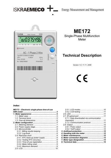
Energy Measurement and Management<br />
<strong>ME172</strong><br />
Single-Phase Multifunction<br />
Meter<br />
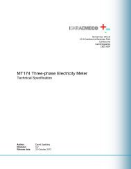
<strong>Technical</strong> <strong>Description</strong><br />
Version 1.6, 11.11. 2008<br />
Index:<br />
<strong>ME172</strong> – Electronic single-phase time-of-use<br />
kWh-meter ................................................................ 3<br />
1. Meter appearance ................................................ 5<br />
1.1. Meter case ...................................................... 5<br />
1.2. Terminal block................................................. 5<br />
1.3. Over-all dimensions ........................................ 6<br />
2. Meter configuration ............................................. 7<br />
2.1. Metering element ............................................ 7<br />
2.2. Power supply stage......................................... 8<br />
2.3. Microcontroller ................................................ 8<br />
2.3.1. Billing results keeping .............................. 8<br />
2.3.2. Log-book .................................................. 8<br />
2.4. Real-time clock ............................................... 9<br />
2.4.1. RTC back-up power supply...................... 9<br />
2.4.2. Testing RTC accuracy.............................. 9<br />
2.4.3. Time-of-use registration ........................... 9<br />
2.4.4. Meter billing reset..................................... 9<br />
2.4.5. Maximum demand.................................... 9<br />
2.5. LCD............................................................... 10<br />
2.5.1. LCD modes.............................................10<br />
2.5.2. LCD testing .............................................11<br />
2.6. LED................................................................11<br />
2.7. IR optical port ................................................11<br />
2.7.1. Data downloaded via communication<br />
channel(s) .........................................................11<br />
2.7.2. Communication protocol.........................11<br />
2.8. Output............................................................12<br />
2.8.1. Pulse output............................................12<br />
2.8.2. Tariff output.............................................12<br />
3. Antifraud protection...........................................12<br />
4. Handling with the meter ....................................12<br />
5. Meter maintenance.............................................12<br />
6. Meter connection diagrams ..............................13<br />
7. Meter type designation......................................13<br />
8. <strong>Technical</strong> data ....................................................14
2 of 16<br />
<strong>ME172</strong> ─ Electronic single-phase<br />
Multifunction Meter
<strong>ME172</strong> ─ Electronic single-phase<br />
Multifunction Meter<br />
<strong>ME172</strong> – Electronic single-phase time-of-use kWh-meter<br />
The <strong>ME172</strong> electronic single-phase meters are designed for measurement and registration of active<br />
energy and demand in single-phase two-wire networks for direct connection. The metering and<br />
technical properties of the meters comply with the EN 50470-1 and -3 European standards classes A<br />
and B as well as with the IEC 62053-21 and IEC 62052-11 (former IEC 61036) international standards for<br />
electronic meters of active energy for classes 2 and 1.<br />
A built-in time switch complies with the IEC 62054-21 and IEC 62052-21 standards. It enables energy<br />
registration in up to four tariffs.<br />
The meters are designed and manufactured in compliance with the ISO 9001 standard.<br />
<strong>ME172</strong> meter properties:<br />
• Meter of active energy<br />
• Accuracy class 1 or 2<br />
• Accuracy class A or B by EN 50470-1<br />
• Demand measurement<br />
• Modes of energy measurement and registration<br />
• For one-way energy flow direction (import), with an electronic reverse running stop<br />
• For two energy flow directions (import, export)<br />
• For one-way energy flow direction, with always positive registration, i.e. energy flowing in the export<br />
direction is registered as it flows in import direction too<br />
• Meter quality:<br />
• Due to high accuracy and long term stability of the metering element no meter recalibration over its lifetime<br />
is required<br />
• Long meter life-time and high meter reliability<br />
• High immunity to EMC<br />
• Time-of-use registration (up to 4 tariffs):<br />
• Tariffs change-over by internal real-time clock<br />
• LCD:<br />
• 7-segment, with 7 + 4 characters, indicators of active tariff - 4 signal flags of active tariff (T1, T2, T3,<br />
T4), 4 signal flags for indicating different meter state and alarms and two arrows for indication of energy<br />
flow-direction.<br />
• wide view angle and back-light<br />
• Optional no-power data display<br />
• Data display modes:<br />
• Automatic cyclic data display with adjustable display time<br />
• Manual data display mode (by pressing the Scroll pushbutton)<br />
• Indicators:<br />
• LCD:<br />
- Valid tariff at the moment<br />
- Meter status and alarms<br />
- Energy flow direction<br />
• LED:<br />
- Imp / kWh<br />
• Communication channel:<br />
3 of 16
<strong>ME172</strong> ─ Electronic single-phase<br />
Multifunction Meter<br />
• Infrared optical port in compliance with the IEC 62056-21 for local meter programming and data downloading<br />
• RS 485 interface (option)<br />
• IEC 62056 – 21, mode C protocol<br />
• Two pushbuttons:<br />
• For data scrolling<br />
• For manual billing reset of the meter<br />
• For manual parameters setting<br />
• Pulse output:<br />
• Class A by IEC 62053-31 (option)<br />
• Optomos relay with make contact (option)<br />
• Antifraud protection:<br />
• Absolute energy measurement (option)<br />
• Metering element in neutral circuit (option)<br />
• Single-wire measurement<br />
• Reversed energy flow detector<br />
• Meter cover opening detector<br />
• Terminal cover opening detector<br />
• External magnet field detector<br />
• Hardware and software protection for programming<br />
• Plastic meter case:<br />
• Made of high quality self-extinguishing UV stabilized material, that can be recycled<br />
• Double insulation<br />
• IP53 protection against dust and water penetration (by IEC 60529)<br />
4 of 16
<strong>ME172</strong> ─ Electronic single-phase<br />
Multifunction Meter<br />
1. Meter appearance<br />
1.1. Meter case<br />
A compact meter case consists of a meter base with a terminal block and two fixing elements for mounting the<br />
meter, a meter cover and a terminal block cover. The meter case is made of self-extinguishing UV stabilized<br />
polycarbonate which can be recycled. The meter case ensures double insulation and IP53 (IEC 60529) protection<br />
level against dust and water penetration.<br />
The meter cover is made of polycarbonate. It is permanently stuck to the meter base so that access to the meter<br />
interior is not possible. Meter data are engraved in the meter cover.<br />
An iron ring is positioned in the right top corner and is used for attaching an optical probe to the optical port.<br />
Two pushbuttons are positioned on the right side of the meter cover. The blue one (5) is always accessible and<br />
is used for data scrolling on the LCD. The covered blue pushbutton (6) can be sealed and is used for resetting<br />
the meter.<br />
On request an element with a third fixing hole can be attached to the back side of the meter base.<br />
11<br />
(1) Hanger<br />
(2) Meter cover (permanently stuck to the meter base)<br />
(3) LCD display<br />
(4) Optical port<br />
(5) Scroll push-button<br />
(6) Covered Reset push-button<br />
(7) LED imp/kWh<br />
(8) Terminal block cover<br />
(9) Terminal cover plastic stopper<br />
(10) Meter data<br />
(11) Place for metrological seal<br />
1.2. Terminal block<br />
The meters are equipped with a terminal block that either complies with the DIN 43857 or the BS 5685<br />
standard. The terminal block accommodates current terminals and optional auxiliary terminals. There is no<br />
potential link as the metering element is based on a shunt. Therefore, during the meters testing they should be<br />
connected via an isolation transformer.<br />
Current terminals are made of solid brass. At the DIN terminal block version the bore diameter is 8.5 mm and<br />
enables connection of conductors with cross sections up to 25 mm 2 . At the BS terminal block version the bore<br />
diameter is 9.5 mm and enables connection of conductors with cross sections up to 35 mm 2 . The conductors<br />
are fixed with two screws. The recommended torque for fixing the conductors is 2.5 Nm.<br />
Up to six auxiliary terminals for optional outputs can be built into the meter on request. The bore diameter of the<br />
auxiliary terminals is 3.5 mm. Wires are fixed with a screw. In addition, two auxiliary voltage terminals for power<br />
supply of an external device can be built-in on request too.<br />
Both current and auxiliary terminals are nickel-plated at a tropical meter version.<br />
5 of 16
<strong>ME172</strong> ─ Electronic single-phase<br />
Multifunction Meter<br />
The terminal cover can be long or short and is fixed with a plastic stopper. A meter connection diagram is stuck<br />
on the inner side of the terminal cover.<br />
Terminal block in compliance with the DIN 43857 standard<br />
A. Current terminals – phase<br />
B. Current terminals – neutral<br />
C. Auxiliary terminals<br />
A B C<br />
Terminal block in compliance with the BS 5685 standard<br />
A. Current terminals – mains<br />
B. Current terminals – load<br />
C. Auxiliary terminals<br />
A<br />
C<br />
B<br />
1.3. Over-all dimensions<br />
Meter fixing dimensions comply with the DIN 43857.<br />
Meter version with short terminal cover<br />
Meter version with long terminal cover<br />
6 of 16
<strong>ME172</strong> ─ Electronic single-phase<br />
Multifunction Meter<br />
2. Meter configuration<br />
Fig.: Meter block-diagram<br />
The meter consists of:<br />
1. Measuring element<br />
2. Meter power supply stage<br />
3. Microprocessor with EEPROM<br />
4. RTC with a Li-battery<br />
5. LCD<br />
6. Impulse LED<br />
7. Scroll pushbutton<br />
8. Reset pushbutton with a cover<br />
9. IR optical port<br />
10. Pulse or tariff output (option)<br />
2.1. Metering element<br />
The metering element enables precise measurement of active energy in a wide metering and a temperature<br />
range.<br />
The metering element consists of a current and a voltage sensor. The current sensor is a shunt, while the<br />
voltage sensor is a resistive voltage divider. Signals of currents and voltages are fed to the A/D converters.<br />
They are digitally multiplied so that instantaneous power is calculated. The instantaneous power is integrated in<br />
a microcontroller, where it is further processed.<br />
Fig.: Metering element<br />
7 of 16
<strong>ME172</strong> ─ Electronic single-phase<br />
Multifunction Meter<br />
The metering element ensures excellent metering properties:<br />
1. Negligible effect of electromagnetic disturbances<br />
and influence quantities<br />
2. High long-term stability so that meter recalibration is not required over its lifetime<br />
3. Long meter lifetime and high reliability in use<br />
2.2. Power supply stage<br />
The power supply stage is a capacitor type, which enables a meter to operate accurately in a voltage range<br />
from 80% to 120% of the rated voltage.<br />
2.3. Microcontroller<br />
The microcontroller acquires signals from the metering elements, processes them and calculates values of<br />
measured energy and demand. The results are stored in energy registers for particular tariffs and stores energy<br />
data in previous billing periods. The microcontroller also generates pulses for the LED and pulse output, drives<br />
the LCD and enables two-way communication via the optical port.<br />
All measured data are stored in a non-volatile memory (EEPROM) and are kept for more than 10 years period<br />
without external power supply.<br />
2.3.1. Billing results keeping<br />
The meter keeps billing results (energy values registered by tariffs and total) for up to last 15 billing periods<br />
(months). A number of billing periods (months) for which billing results are kept is set in the factory and can not be<br />
changed subsequently. The billing results are stored in a FIFO memory, so that they are always available for the<br />
last n (n = 1, 2, …15) billing periods (months), regardless if the meter billing reset was performed by means of the<br />
RTC, the Reset pushbutton or via the optical port. The metering results of the past billing periods (months) can be<br />
displayed (9) or down-loaded (15) via the optical port.<br />
The billing reset can be set to be executed by the RTC:<br />
• Single on a specified date and time<br />
• Once a year on a specified date and time<br />
• Every month on specified day in a month and time<br />
• Every month on a specified day in a week after specified day in a month and specified time<br />
• Every week on a specified day in a week and time<br />
• Every day on a specified time<br />
Billing reset blockade:<br />
• the billing reset blockade timeout is minimal time between two billing resets<br />
• blockade timeout can be set from 1 to 1092 min<br />
• blockade timeout is reset if meter is disconnected from main supply voltage<br />
• billing reset blockade is valid only for push-button reset and reset via communication port<br />
2.3.2. Log-book<br />
The microcontroller registers 128 events and meter statuses in a log-book. It is organized as a FIFO memory,<br />
which means that the last 128 events are always available. The following events and meter statuses can be<br />
registered in a log-book:<br />
• Fatal meter error<br />
• Meter billing reset<br />
• Changing the value of set parameters<br />
• Internal clock setting<br />
• Network voltage failure<br />
• Restoration of network voltage<br />
• Deleting log-book registers<br />
8 of 16
<strong>ME172</strong> ─ Electronic single-phase<br />
Multifunction Meter<br />
2.4. Real-time clock<br />
A real-time clock is controlled with a 32.768 kHz quartz crystal which is digitally trimmed. Its accuracy is better<br />
than requested in the IEC 62054-21 standard for time switches. The RTC involves an internal calendar that<br />
assures information on year, month, day, day in a week, hour, minute, second and leap year.<br />
The RTC enables:<br />
• Time-of-use registration (in max. 4 tariffs),<br />
• Generation of demand periods<br />
• Generation of time stamp (date and time) for demand and events<br />
• Automatic meter billing reset at the end of the billing period (month)<br />
• Automatic change-over to daylight saving period and back (winter – summer time).<br />
2.4.1. RTC back-up power supply<br />
An Li-battery is used as the RTC back-up power supply. It assures 5 years of the RTC operation reserve and<br />
has 15-year lifetime. The lithium battery is positioned on the meter printed circuit board under the meter cover.<br />
On request the Li-battery enables data display when the meter is in a no-power state. If this function is built in<br />
the meter, a blue pushbutton should be pressed when the meter is not connected to the network or there is no<br />
voltage in order to display data on the LCD. The blue pushbutton should be pressed again and again for<br />
displaying next data. If the blue key is not pressed in the time to manual display timeout (set in the factory to 60<br />
sec.), the LCD is automatically switched off.<br />
2.4.2. Testing RTC accuracy<br />
The RTC accuracy can be tested via the imp/kWh LED, when the meter is in the RTC test mode. The meter is<br />
set in the RTC test mode via the optical port by means of the <strong>Iskraemeco</strong> Meter-View software so that a<br />
command Clock control is sent to the meter. When the meter is in the RTC test mode, the RTC 4096 Hz test<br />
frequency is fed to the imp/kWh LED. The meter will stay in the RTC test mode approximately 18 hours. Then it<br />
will return back into the meter mode automatically. Other ways to exit from the RTC test mode are:<br />
• By sending a command to exit RTC test mode by means of the MeterView software<br />
• By disconnecting a meter from the voltage supply<br />
2.4.3. Time-of-use registration<br />
The meter is designed as a multi-tariff with maximum four tariffs. A tariff change-over time is defined with hour<br />
and minute. Minimal time period between change-over is five minute. The real-time clock enables complex daily<br />
and weekly tariff structures, as well as a couple of seasons in a year:<br />
• Up to 10 seasons in a year, resolution for season is 1 hour<br />
• up to 10 weekly tariff programs<br />
• Up to 10 daily definitions of the tariff change-over program<br />
• Up to 10 tariff change-over inside individual daily tariff programs<br />
• up to 4 tariff<br />
• Up to 46 holidays (including those based on a lunar calendar) in which a special tariff program is defined.<br />
• tariff program can be set up with the MeterView software package<br />
2.4.4. Meter billing reset<br />
A meter billing reset is usually done by RTC once a month. However, any other period of a meter billing reset<br />
can also be set (see Item “Billing results keeping”). Day and time of the meter billing reset can be set for any<br />
day in a month and any time during a day. At a meter billing reset the billing data for a current month are<br />
transferred from the registers for a current month (a billing period) to the registers of a previous month (a billing<br />
period, while the registers of a current month (a billing period) are deleted in order to be ready for measurement<br />
in the next month (a billing period). At the same time a counter of billing resets is incremented.<br />
The meter billing reset can be also performed by pressing the Reset pushbutton, via the IR optical port.<br />
2.4.5. Maximum demand<br />
The internal clock generates a measuring period for demand calculation. Demand is calculated as a mean value<br />
in the measuring period. In the <strong>ME172</strong> meters the following measuring periods can be set: 5, 15, 30 or 60<br />
minutes. At the end of a measuring period, the calculated demand is transferred from the current measuring<br />
period register to the register of the measuring period that was just terminated. It is compared with the value<br />
9 of 16
<strong>ME172</strong> ─ Electronic single-phase<br />
Multifunction Meter<br />
stored in the maximum demand in the billing period. If the new calculated demand is greater than the value in<br />
the maximum demand register, a new demand value is stored, otherwise the old value is kept. In this way, a<br />
maximum demand is also registered at a meter billing reset.<br />
• Measuring period is synchronized with the real time clock<br />
• up to 4 tariff, equal tariff program for MD and time-of-use registration<br />
• at power-down the measuring period is finished<br />
• at power-up the new measuring period is started, the end of new period is synchronized with the real<br />
time clock<br />
• tariff change over - tariff changeover for MD is delayed, the end of measuring period is synchronized<br />
with the real time clock<br />
• billing reset - measuring period is finished, new measuring period is started<br />
• real time clock setup - measuring period is finished, new measuring period is started<br />
2.5. LCD<br />
The 7-segment LCD has 7 characters for data display, 4 characters for data identification codes, 4 signal flags<br />
of active tariff (T1, T2, T3, T4), 4 signal flags for indicating different meter state and alarms and two arrows for<br />
indication of energy flow-direction. Large characters and a wide angle of view, as well as optional LCD backlight,<br />
enable easy data reading.<br />
LCD display:<br />
1. Energy flow-direction<br />
2. Data identification code<br />
3. Data display<br />
4. Signal flags for indicating different<br />
meter state and alarms<br />
The data characters are 12.5 mm high. For data identification four characters are employed, they are 8.5 mm<br />
high. The standard data identification codes are EDIS. The meaning of signal flags are engraved on the meter<br />
name plate below them.<br />
Two arrows in the left upper corner indicate energy flow direction. Only one of them is displayed at the time<br />
indicating import direction () or export direction () of energy flow.<br />
Data defined in Auto scroll sequence and in Manual scroll sequence are displayed on the LCD. Data from Auto<br />
scroll sequence are displayed in a circle, and each data is displayed for 8 sec. as a standard display time. On<br />
request, longer or shorter data display time can be set via the meter optical port by means of <strong>Iskraemeco</strong><br />
MeterView software. At Manual scroll sequence the blue push-button should be pressed for displaying the next<br />
piece of data. Data in Manual scroll sequence remains displayed until the push-button is pressed again or until<br />
time for automatic return into the Auto scroll sequence is elapsed.<br />
Max. number of register in sequence:<br />
• Auto-scroll: 34<br />
• Manual-scroll: 50<br />
Optionally, data can be displayed on the LCD in a no-power meter state by pressing the Data scroll push-button.<br />
2.5.1. LCD modes<br />
The LCD is menu-driven and is handled by pressing one pushbutton at a time. The LCD has the following modes<br />
of data display:<br />
• Starting mode<br />
• Auto scroll mode<br />
• Manual scroll mode<br />
• Parameters setting mode<br />
• Meter testing mode<br />
10 of 16
<strong>ME172</strong> ─ Electronic single-phase<br />
Multifunction Meter<br />
2.5.2. LCD testing<br />
The LCD can be tested automatically so that all LCD segments are displayed for 3 seconds to check if they are<br />
in order. The LCD test can be performed either in:<br />
• the Starting mode (after voltage is applied to the meter)<br />
• the Auto scroll mode or<br />
• Manual scroll mode<br />
• with command through communication interface<br />
2.6. LED<br />
The meter is provided with a LED on the front plate. The imp/kWh LED has two functions depending on the<br />
meter mode. In the meter mode it is used for testing the meter accuracy and blinks with a pulse rate 1,000<br />
imp/kWh, the pulses width is 40 ms.<br />
In the RTC testing mode the LED is used for testing the RTC accuracy and blinks with 4096 Hz test frequency.<br />
2.7. IR optical port<br />
The optical port is in the right top corner. On the meter cover there is an iron plate that enables attaching an<br />
optical probe to the optical port. An optical probe should be so attached that its cable is perpendicular to the<br />
meter bottom edge.<br />
The optical port complies with the IEC 62056-21 and is used for local meter programming and data downloading.<br />
It is located in the right top corner of the meter. The communication protocol complies with IEC 62056-<br />
21, mode C. The communication is serial asynchronous with data transmission rate from 300 bit/sec to 19,200<br />
bit/sec. If data transmission rate of the used optical probe is lower than 19,200 bit/sec, the maximum<br />
permissible data transmission rate is equal to that value. If higher data transmission rate is set, communication<br />
via optical port will not be possible.<br />
The optical port wavelength is 660 nm and luminous intensity is min. 1 mW/sr for the ON state.<br />
2.7.1. Data downloaded via communication channel(s)<br />
Data downloaded via IR optical port are identified with EDIS codes. Besides data for a current billing period, if<br />
requested, the historical data of previous billing periods can be down-loaded via the IR optical port too.<br />
Historical data can be downloaded for the maximum 15 last billing periods.<br />
Built-in communication channels enable:<br />
• Billing data readout<br />
• Log book registers readout<br />
• Meter parameters readout<br />
• Meter parameters setting<br />
LED STATUS INDICATION<br />
Imp/kWh<br />
Blinks<br />
Lit<br />
OFF<br />
Energy is registered. The pulse rate is<br />
proportional to demand<br />
Voltage applied to the meter, but load<br />
current is lower than the meter starting<br />
current.<br />
No voltage is applied to the meter.<br />
The meters can be equipped with the following communication channels:<br />
• Optical interface (low priority) - if RS485 interface is active, optical communication is interrupted<br />
• RS485 interface (high priority)<br />
2.7.2. Communication protocol<br />
The communication protocol is IEC 62056-21 (former IEC 61107), mode C. The communication is asynchronous<br />
half-duplex.<br />
11 of 16
<strong>ME172</strong> ─ Electronic single-phase<br />
Multifunction Meter<br />
2.8. Output<br />
The <strong>ME172</strong> meters can be equipped either with pulse or tariff output.<br />
2.8.1. Pulse output<br />
Optionally the meter can be equipped with one pulse output. Impulse output is passive and complies with the<br />
requirements stated in the IEC 62053-32 standard, class A (S0 in compliance with DIN 43864). Impulse<br />
constant is equal to the half of the meter constant, impulse width is 30 ms. However, a smaller impulse constant<br />
or a larger impulse length can be set on request. If different impulse length and impulse constants are required,<br />
it is necessary to select such their values that prevents lapping of impulses at maximum load.<br />
On request, the impulse output can be performed as an optomos relay with a make contact that can switch 25<br />
W (100 mA, 250 V).<br />
2.8.2. Tariff output<br />
Optionally the meter can be equipped with one tariff output. The tariff output is an optomos relay with a make<br />
contact with switching capability 25 VA (100 mA at 250 V). It can be set as active or not active for each tariff.<br />
3. Antifraud protection<br />
Special attention is paid to a system of meter data protection in order to prevent meter tampering by use of<br />
hardware and software counter measures as well as a meter design itself.<br />
• Absolute energy measurement (option)<br />
• Metering element in neutral circuit (option)<br />
• Single-wire measurement<br />
• Reversed energy flow detector<br />
• Meter cover opening detector<br />
• Terminal cover opening detector<br />
• External magnet field detector<br />
• Hardware and software protection for programming<br />
• Log-book<br />
• Events counters and time stamps<br />
• Signal flags on LCD for fraud attempts<br />
• Meter cover stuck to meter base<br />
4. Handling with the meter<br />
Two sets of tools are available for personal which will manage the meters:<br />
• For service programming and readout:<br />
• MeterView (<strong>Iskraemeco</strong> software)<br />
• An optical probe<br />
• PC: a desktop, a laptop<br />
The tool is intended for the staff that service or reprogram the meters in the laboratory or in the field.<br />
• For billing readout and programming:<br />
• MeterRead (<strong>Iskraemeco</strong> software) for all types of handheld units operating in the Windows CE environment<br />
• An optical probe<br />
The tool is intended for meter readers in the field.<br />
5. Meter maintenance<br />
The meter is designed and manufactured in such a way that no maintenance is required in the entire meter<br />
lifetime. Measuring stability assures that no recalibration is required. If a battery is built into the meter, its<br />
capacity is sufficient to backup all functions for the entire meter lifetime.<br />
12 of 16
<strong>ME172</strong> ─ Electronic single-phase<br />
Multifunction Meter<br />
6. Meter connection diagrams<br />
The meter connection diagrams in compliance with DIN 43857 and BS 5685 standards respectively are shown<br />
in the figure:<br />
7. Meter type designation<br />
<strong>ME172</strong>-D1A52-G12-M3K03<br />
M Electronic meter<br />
E Single-phase meter<br />
172 Multirate meter with internal time-switch<br />
D1 Terminal block for direct connection<br />
up to 85 A by DIN 43857<br />
D3 Terminal block for direct connection<br />
up to 100 A by BS 5685<br />
D31 Terminal block for Imax = 100 A with two<br />
metering systems - DIN connection<br />
D32 Terminal block for Imax = 100 A with two<br />
metering systems - BS connection<br />
A4 Active energy measurement, accuracy<br />
class 1 (class B by EN 50470-3)<br />
A5 Active energy measurement, accuracy<br />
class 2 (class A by EN 50470-3)<br />
1 One energy flow direction<br />
2 Two energy flow directions<br />
4 Absolute registration<br />
G12 S0 pulse output (option)<br />
L11 Pulse output optomos relay with make<br />
contact (option)<br />
M3 Internal time switch with Li-battery<br />
K Communication interface<br />
0 Optical port by IEC 62056-21 (IEC 61107)<br />
3 RS 485 interface (option)<br />
Fig.: Meter connection diagrams<br />
13 of 16
<strong>ME172</strong> ─ Electronic single-phase<br />
Multifunction Meter<br />
8. <strong>Technical</strong> data<br />
GENERAL METER PROPERTIES<br />
Reference voltage U n<br />
230 V (other voltage on request)<br />
Voltage range<br />
0,8 U n ... 1,15 U n (from 0,2 U n to 1,3 U n error of the meter in class)<br />
Reference frequency f n<br />
50 Hz or 60 Hz<br />
IEC SPECIFIC DATA (IEC 62052-11, IEC 62053-21, IEC 62053-23)<br />
Accuracy class for active energy 2 or 1 (IEC 62053-21)<br />
Basic current I b<br />
5A<br />
Maximum current I max<br />
DIN terminal: 85 A<br />
BS terminal: 100 A<br />
Starting current I st
<strong>ME172</strong> ─ Electronic single-phase<br />
Multifunction Meter<br />
RTC<br />
Time base<br />
Surge (IEC 61000-4-5)<br />
In voltage and current circuits (main lines): 4 kV<br />
In auxiliary circuits with reference voltage over 40 V: 1 kV<br />
Conducted disturbances, inducted by RF fields (IEC 61000-4-6)<br />
from 150 kHz to 80 MHz<br />
voltage level 20 V (higher then standard requirements)<br />
Power frequency magnetic fields of external origin (IEC 61000-4-8)<br />
Field strength 0,5 mT error deviation (IEC 62053-21/EN50470-3)
<strong>ME172</strong> ─ Electronic single-phase<br />
Multifunction Meter<br />
Owing to periodically improvements of our products the supplied products can differ in some details from data stated in this technical<br />
description.<br />
<strong>Iskraemeco</strong> d.d., Energy Measurement and Management 4000 Kranj, Savska loka 4, Slovenia<br />
Telephone (+386 4) 206 40 00, Fax: (+386 4) 206 43 76<br />
http://www.iskraemeco.si, E-mail: info@iskraemeco.si<br />
Published: <strong>Iskraemeco</strong>, Marketing, Data subjected to alteration without notice.<br />
<strong>ME172</strong>_TD_v6_Eng.doc<br />
16 of 16