Variable Valve Timing & Acoustic Control Induction ... - NewsGuy
Variable Valve Timing & Acoustic Control Induction ... - NewsGuy
Variable Valve Timing & Acoustic Control Induction ... - NewsGuy

Create successful ePaper yourself
Turn your PDF publications into a flip-book with our unique Google optimized e-Paper software.
Section 8<br />
<strong>Variable</strong> <strong>Valve</strong> <strong>Timing</strong> & <strong>Acoustic</strong> <strong>Control</strong> <strong>Induction</strong> Systems<br />
ECM<br />
Crankshaft Position Sensor<br />
Mass Air Flow Meter<br />
Target <strong>Valve</strong> <strong>Timing</strong><br />
Feedback<br />
Camshaft<br />
<strong>Timing</strong> Oil<br />
<strong>Control</strong> <strong>Valve</strong><br />
Throttle Position Sensor<br />
Engine Coolant Temp. Sensor<br />
Correction<br />
VVT Sensor<br />
Actual <strong>Valve</strong> <strong>Timing</strong><br />
T852f286<br />
Lesson Objectives<br />
1. Familiarity with the VVT-i systems and ACIS systems operation<br />
Engine <strong>Control</strong> Systems I - Course 852
Section 8<br />
<strong>Variable</strong> <strong>Valve</strong> <strong>Timing</strong> & <strong>Acoustic</strong> <strong>Control</strong> <strong>Induction</strong> Systems<br />
VVT-i System<br />
Throttle Position Sensor<br />
Camshaft <strong>Timing</strong> Oil <strong>Control</strong><br />
VVT Sensor<br />
Camshaft <strong>Timing</strong> Oil <strong>Control</strong><br />
VVT Sensor<br />
Engine Coolant Temp. Sensor<br />
ECM<br />
Crankshaft Position Sensor<br />
Mass Air<br />
Flow Meter<br />
ECM<br />
Crankshaft Position Sensor<br />
Mass Air Flow Meter<br />
Target <strong>Valve</strong> <strong>Timing</strong><br />
Feedback<br />
Camshaft<br />
<strong>Timing</strong> Oil<br />
<strong>Control</strong> <strong>Valve</strong><br />
Throttle Position Sensor<br />
Duty <strong>Control</strong><br />
Engine Coolant Temp. Sensor<br />
Correction<br />
VVT Sensor<br />
Actual <strong>Valve</strong> <strong>Timing</strong><br />
Fig. 8-01<br />
T852f285/T852f286<br />
<strong>Variable</strong> <strong>Valve</strong><br />
<strong>Timing</strong><br />
Systems<br />
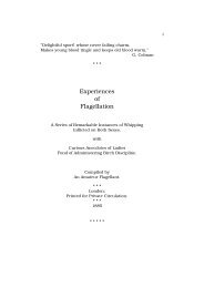
Without variable valve timing, engine valve timing is a compromise<br />
between the needs to produce maximum torque (horsepower) at low to<br />
medium speeds, idle stability, fuel economy, low emissions, and maximum<br />
horsepower output. Continuously adjusting when the valves open<br />
and close, called variable valve timing, yields significant improvements<br />
in all these areas. The ECM, according to driving conditions such as the<br />
engine speed and load, will advance or retard the camshaft, changing<br />
when the valves open and close. This system is called the <strong>Variable</strong> <strong>Valve</strong><br />
<strong>Timing</strong>-intelligent (VVT-i) system.<br />
Engine <strong>Control</strong> Systems I - Course 852 8-1
Section 8<br />
VVT-i Range<br />
The G signal represents<br />
the movement of the<br />
camshaft in degrees in<br />
relation to the crankshaft.<br />
G 2<br />
<strong>Control</strong>lable<br />
Range of VVT-i<br />
Advanced Side<br />
Most Delayed Angle Position<br />
<strong>Control</strong>lable<br />
Range of VVT-i<br />
Most Advanced<br />
Angle Position<br />
NE Signal<br />
Crankshaft Angle<br />
G 2 Signal<br />
0 120 240 360<br />
#6 TDC #2 TDC #4 TDC #1 TDC<br />
<strong>Control</strong>lable Range of VVT-i<br />
NE Signal<br />
Crankshaft Angle<br />
360 480 600 720<br />
#1 TDC #5 TDC #3 TDC #6 TDC<br />
Phase Relationship Between G 2 and NE Signal<br />
Fig. 8-02<br />
T852f287<br />
Components of<br />
VVT-i<br />
VVT-i uses the crankshaft position sensor and <strong>Variable</strong> <strong>Valve</strong> <strong>Timing</strong><br />
(V V T ) sensors (camshaft position sensor) to measure the amount of<br />
camshaft movement. This feedback is necessary for the ECM to know<br />
how much and which direction to move the camshaft, and for diagnosis.<br />
A continuously variable valve timing mechanism, called a controller or<br />
actuator, is used to adjust the camshaft from the starting stage to the<br />
high speed traveling state.<br />
A camshaft timing Oil <strong>Control</strong> <strong>Valve</strong> (OCV), controlled by the ECM,<br />
directs engine oil pressure to the advance or retard side of the VVT-i<br />
controller.<br />
Effect of Continuous<br />
<strong>Valve</strong> <strong>Timing</strong><br />
Changes<br />
Smooth Idle - At idle rpm, valve overlap is eliminated by retarding the<br />
camshaft. With the intake valve opening after the exhaust valve has<br />
closed, there is no blow back of exhaust gases to the intake side. Now,<br />
combustion is more stable because of the clean air/fuel mixture. This<br />
allows the engine idle smoothly at a lower rpm and fuel consumption is<br />
reduced.<br />
Torque Improvement in Low to Medium Speed Range - In the low to<br />
medium speed range with a heavy load, the camshaft is advanced<br />
increasing the valve overlap. This has two effects. First, the exhaust<br />
gases help pull in the intake mixture. Second, by closing the intake<br />
valve early, the air/fuel mixture taken into the cylinder is not discharged.<br />
8-2<br />
TOYOTA Technical Training
<strong>Variable</strong> <strong>Valve</strong> <strong>Timing</strong> & <strong>Acoustic</strong> <strong>Control</strong> <strong>Induction</strong> Systems<br />
This improves volumetric efficiency and increases torque (and therefore<br />
horsepower) in the low and midrange rpm range. The driver notices a<br />
more powerful acceleration.<br />
EGR Effect - VVT-i eliminates the need for an EGR valve. As a result of<br />
increasing the valve overlap in which the exhaust and intake valves are<br />
both open, the exhaust gas is able to flow to the intake side. Diluting the<br />
air/fuel mixture with exhaust gases reduces the combustion temperature<br />
and the production of NO x . Also, some of the unburned air/fuel mixture<br />
present in the exhaust gas will be burned.<br />
Better Fuel Economy - A VVT-i equipped engine is more efficient and<br />
provides better fuel economy from a variety of factors. Without VVT-i, the<br />
engine would have to be larger and heavier to produce the same horsepower.<br />
Smaller pistons, connecting rods, and crankshaft reduce friction<br />
and mechanical losses. A lighter engine improves vehicle fuel economy.<br />
Improved fuel consumption is also realized because of the further reduction<br />
in the intake stroke resistance. In the medium-load operation range,<br />
when the valve overlap is increased, the vacuum (negative pressure) in<br />
the intake manifold is reduced. Now, it takes less energy to move the piston<br />
downward on the intake stroke. With the pumping loss reduced during<br />
the intake stroke, more energy is available to propel the vehicle.<br />
At idle, with no valve overlap, the idle speed is lower improving fuel economy.<br />
Improved Emission <strong>Control</strong> Performance - In the light-medium load<br />
operation range, VVT-i increases the valve overlap creating an internal<br />
EGR effect. By opening the intake valve earlier in the exhaust stroke at a<br />
lower RPM allows the exhaust gases to push into the intake manifold<br />
mixing with the fresh air. The return of exhaust gas into the cylinder lowers<br />
the combustion temperature, resulting in NO x reduction. Essentially,<br />
VVT-i will increase the valve overlap to obtain the same EGR effect as an<br />
engine equipped with an EGR valve. In other words, when an EGR valve<br />
on an EGR equipped engine opens is when VVT-i will increase the valve<br />
overlap.<br />
Another benefit is that HCs are also reduced. Some of the unburned<br />
air/fuel mixture from the previous cycle returns to the cylinder for combustion.<br />
Finally, C0 2 is reduced because of the decrease in fuel consumption.<br />
Engine <strong>Control</strong> Systems I - Course 852 8-3
Section 8<br />
Oil <strong>Control</strong> <strong>Valve</strong><br />
(OCV)<br />
To <strong>Timing</strong> Pulley<br />
(Advanced Side)<br />
Coil<br />
(Retard Side)<br />
Spring<br />
Drain<br />
Oil Pressure<br />
Drain<br />
Spool <strong>Valve</strong><br />
Plunger<br />
Exhaust <strong>Valve</strong><br />
<strong>Variable</strong> Angle (50º)<br />
Intake <strong>Valve</strong><br />
<strong>Valve</strong> Lift<br />
<strong>Valve</strong> <strong>Timing</strong><br />
Crankshaft Angle<br />
Fig. 8-03<br />
T852f288/T852f289<br />
Operation<br />
Camshaft <strong>Timing</strong><br />
Oil <strong>Control</strong> <strong>Valve</strong><br />
The Camshaft <strong>Timing</strong> Oil <strong>Control</strong> <strong>Valve</strong> (OCV), controlled by the ECM,<br />
directs engine oil pressure to the advance or retard side of the VVT-i<br />
controller. The spool valve position is determined by the magnetic field<br />
strength opposing the spring. As the ECM increases the pulsewidth<br />
(duty ratio), the magnetic field moves the spool valve overcoming spring<br />
pressure and directing more oil to the advance side. To retard the timing,<br />
the ECM decreases the pulsewidth, and spring pressure moves the<br />
spool valve towards the retard position. When the desired camshaft<br />
angle is achieved, the ECM will generate a pulsewidth signal to move<br />
the spool valve to hold position. In the hold position, the oil is trapped<br />
in the controller maintaining the desired angle. When the engine is<br />
stopped, the spring pushes the spool valve to the most retarded state.<br />
8-4<br />
TOYOTA Technical Training
<strong>Variable</strong> <strong>Valve</strong> <strong>Timing</strong> & <strong>Acoustic</strong> <strong>Control</strong> <strong>Induction</strong> Systems<br />
VVT-i <strong>Control</strong>ler Assembly<br />
<strong>Timing</strong> Pulley<br />
VVT Tube<br />
Piston<br />
Inner Gear<br />
Intake Camshaft<br />
Outer Gear<br />
Exhaust Camshaft<br />
Scissors Gear<br />
Fig. 8-04<br />
T852f290<br />
V V T-i <strong>Control</strong>ler<br />
The helical splines force the camshaft to<br />
advance or retard in relation to the timing<br />
pulley.<br />
Outer Gear<br />
<strong>Timing</strong> Pulley<br />
Helical Spline<br />
(Inner Gear)<br />
Helical Spline<br />
Intake Camshaft<br />
Inner Gear<br />
Piston<br />
Piston<br />
Fig. 8-05<br />
T852f291/T852f292<br />
VVT-i <strong>Control</strong>ler<br />
(Helical Type)<br />
Operation<br />
This VVT-i controller comprises of an outer gear driven by the timing<br />
belt, an inner gear affixed to the camshaft, and a movable piston that is<br />
placed between the outer gear and inner gear. As the piston moves laterally<br />
(axially), the helical splines on the piston and inner gear force the<br />
camshaft to move in relation to the timing gear.<br />
Engine <strong>Control</strong> Systems I - Course 852 8-5
Section 8<br />
Advance<br />
By the command of the<br />
ECM, when the OCV is<br />
in the position shown,<br />
hydraulic pressure is<br />
applied from the left side<br />
of the piston, which<br />
causes the piston to<br />
move to the right.<br />
Because of the twist in<br />
the helical splines on the<br />
inside diameter of the<br />
piston, the intake<br />
camshaft rotates in the<br />
advance direction in<br />
relation to the camshaft<br />
timing pulley.<br />
Piston<br />
<strong>Timing</strong> Pulley<br />
Intake<br />
Camshaft<br />
Camshaft <strong>Timing</strong><br />
Oil <strong>Control</strong> <strong>Valve</strong><br />
Drain<br />
Oil Pressure<br />
Fig. 8-06<br />
T852f293<br />
Retard<br />
When the OCV is in the<br />
position shown, the<br />
piston moves to the left<br />
and rotates the camshaft<br />
in the retard direction.<br />
Piston<br />
Drain<br />
Oil Pressure<br />
Fig. 8-07<br />
T852f294<br />
8-6<br />
TOYOTA Technical Training
<strong>Variable</strong> <strong>Valve</strong> <strong>Timing</strong> & <strong>Acoustic</strong> <strong>Control</strong> <strong>Induction</strong> Systems<br />
Hold<br />
To hold to the desired<br />
position, the OCV shuts<br />
off the oil passages to<br />
maintain the hydraulic<br />
pressure at both sides of<br />
the piston, thus<br />
maintaining that position.<br />
Fig. 8-08<br />
T852f295<br />
VVT-i Actuator (Vane Type)<br />
Lock Pin<br />
Housing<br />
(Fixed on driven gear)<br />
Vane Seal<br />
Exhaust Camshaft<br />
VVT-i <strong>Control</strong>lers<br />
Housing<br />
Side<br />
Hydraulic<br />
Pressure<br />
Vane<br />
Portion<br />
(Fixed on<br />
intake<br />
camshaft)<br />
Intake Camshafts<br />
Driven Gear<br />
Exhaust Camshaft<br />
Fig. 8-09<br />
T852f296/T852f297<br />
VVT-i Actuator<br />
(Vane Type)<br />
Operation<br />
This controller consists of a housing driven by the exhaust camshaft and<br />
a vane fixed to the intake camshaft. Oil pressure is directed to either side<br />
of the vane causing the camshaft to rotate in relation to the driven gear.<br />
Engine <strong>Control</strong> Systems I - Course 852 8-7
Section 8<br />
VVT-i Operation<br />
Operation<br />
Camshaft <strong>Timing</strong><br />
Oil <strong>Control</strong> <strong>Valve</strong><br />
Drive Signal<br />
Description<br />
Advance<br />
Rotating<br />
Direction<br />
VVT-I <strong>Control</strong>ler<br />
Oil<br />
Pressure<br />
ECM<br />
Duty Ratio<br />
When the camshaft timing oil<br />
control valve is positioned as<br />
illustrated at left by the<br />
advance signal from the<br />
ECM, the resultant oil pressure<br />
is applied to the timing<br />
advance side vane chamber<br />
to rotate the camshaft in the<br />
timing advance direction.<br />
Retard<br />
Rotating<br />
Direction<br />
Vane (Fixed on<br />
intake camshaft)<br />
Oil<br />
Pressure<br />
ECM<br />
Duty Ratio<br />
When the camshaft timing oil<br />
control valve is positioned as<br />
illustrated at left by the<br />
retard signal from the ECM,<br />
the resultant oil pressure is<br />
applied to the timing retard<br />
side vane chamber to rotate<br />
the camshaft in the timing<br />
retard direction.<br />
Hold<br />
Vane (Fixed on<br />
intake camshaft)<br />
Oil<br />
Pressure<br />
ECM<br />
Duty Ratio<br />
The ECM calculates the target<br />
timing angle according to<br />
the traveling state to perform<br />
control as described above.<br />
After setting at the target<br />
timing, the camshaft timing<br />
oil control valve is in the neutral<br />
position unless the traveling<br />
state changes. This<br />
adjusts the valve timing at<br />
the desired target position<br />
and prevents the engine oil<br />
from running out when it is<br />
unnecessary.<br />
Fig. 8-10<br />
T852f298/T852f299<br />
T852f300/T852f301<br />
T852f302/T852f303<br />
8-8<br />
TOYOTA Technical Training
<strong>Variable</strong> <strong>Valve</strong> <strong>Timing</strong> & <strong>Acoustic</strong> <strong>Control</strong> <strong>Induction</strong> Systems<br />
<strong>Variable</strong> <strong>Valve</strong> <strong>Timing</strong> with<br />
Lift - intelligent (VVTL-i)<br />
Camshaft Position Sensor<br />
Oil <strong>Control</strong> <strong>Valve</strong> (<strong>Variable</strong> <strong>Valve</strong> <strong>Timing</strong> and Lift)<br />
Engine Coolant Temp Sensor<br />
Throttle Position<br />
Sensor<br />
ECM<br />
Oil <strong>Control</strong> <strong>Valve</strong><br />
(<strong>Variable</strong> <strong>Valve</strong> <strong>Timing</strong>)<br />
Mass Air Flow<br />
Meter<br />
Crankshaft Position Sensor<br />
Fig. 8-11<br />
T852f304<br />
VVTL-i<br />
Low and Medium Lift or High Lift<br />
Oil <strong>Control</strong> <strong>Valve</strong> (<strong>Variable</strong><br />
<strong>Valve</strong> <strong>Timing</strong> and Lift)<br />
Crankshaft Position Sensor<br />
Mass Air Flow Meter<br />
Throttle Position<br />
Target Value <strong>Timing</strong><br />
Feedback<br />
Oil <strong>Control</strong> <strong>Valve</strong><br />
(<strong>Variable</strong> <strong>Valve</strong> <strong>Timing</strong><br />
Duty <strong>Control</strong><br />
Engine Coolant Temp. Sensor<br />
Correction<br />
Camshaft Position Sensor<br />
Actual <strong>Valve</strong> <strong>Timing</strong><br />
Fig. 8-12<br />
T852f305<br />
<strong>Variable</strong> <strong>Valve</strong><br />
<strong>Timing</strong> Liftintelligence<br />
System<br />
Based on the VVT-i system, the <strong>Variable</strong> <strong>Valve</strong> <strong>Timing</strong> with Lift - intelligent<br />
(VVTL-i) system has adopted a cam changeover mechanism that<br />
changes the amount of lift and duration of the intake and exhaust valves<br />
while the engine is operating at high speeds. In addition to achieving<br />
higher engine speeds and higher outputs, this system enables the valve<br />
timing to be optimally set, resulting in improved fuel economy.<br />
Engine <strong>Control</strong> Systems I - Course 852 8-9
Section 8<br />
When the engine is operating in the low-to-mid-speed range, the<br />
low/medium-speed cam lobes of the camshafts operate to move the two<br />
valves via the rocker arms. Then, when the engine is operating in the<br />
high-speed range, the signals from the sensors cause the ECM to<br />
change the hydraulic passage of the oil control valve, thus changing to<br />
the high-speed cam lobes. Now, the lift and the duration of the intake<br />
and exhaust valves increases, allowing a greater volume of the air/fuel<br />
mixture to enter the cylinder, and a greater volume of the exhaust gases<br />
to leave the cylinder. As a result, the engine produces more power over<br />
a wider RPM range.<br />
The construction and the operation of the valve timing control are basically<br />
the same as in the VVT-i system.<br />
Camshaft Lobes<br />
Low and Medium<br />
Speed Cam<br />
Exhaust Camshaft<br />
Intake Camshaft<br />
High Speed Cam<br />
Fig. 8-13<br />
T852f306<br />
8-10<br />
TOYOTA Technical Training
<strong>Variable</strong> <strong>Valve</strong> <strong>Timing</strong> & <strong>Acoustic</strong> <strong>Control</strong> <strong>Induction</strong> Systems<br />
Rocker Arm<br />
Assembly<br />
Rocker Arm Pad<br />
Needle Roller<br />
(Integrated with Rocker Arm)<br />
Rocker Arm<br />
Rocker Shaft<br />
A<br />
Adjusting Shim<br />
Rocker Arm Pin<br />
<strong>Valve</strong><br />
Fig. 8-14<br />
T852f307<br />
Construction<br />
The main components of the rocker arm assembly are the rocker arm,<br />
rocker arm pad, rocker arm pin, and the rocker shaft. This assembly is<br />
used for both the intake and exhaust camshafts, with each connected to<br />
its respective rocker arm shaft. Both the intake and exhaust camshafts<br />
contain low and medium-speed cams and high-speed cams.<br />
Rocker Arm<br />
Assembly (Cams)<br />
High Speed Cam<br />
Low and Medium<br />
Speed Cam<br />
Rocker Arm Pad<br />
Adjusting Shim<br />
Rocker Arm Pin<br />
A of View<br />
Fig. 8-15<br />
T852f308<br />
Engine <strong>Control</strong> Systems I - Course 852 8-11
Section 8<br />
Operation<br />
When the engine coolant temperature is higher than 60°C (140°F) and<br />
the engine speed is higher than 6000 RPM, this system switches from<br />
the low/medium speed cams to the high-speed cams.<br />
Low/Medium Speed Operation<br />
High Speed Cam<br />
When the engine is operating in the low-to<br />
mid-speed range (below 6000 RPM), the<br />
low and medium-speed cam pushes the<br />
needle roller of the rocker arm down to<br />
operate the two valves. At this time, the<br />
high-speed cam is also pushing down on<br />
the rocker arm pad, but because the rocker<br />
arm pad moves freely, this movement does<br />
not cause the rocker arm and the valves to<br />
move.<br />
Low and Medium<br />
Speed Cam<br />
Rocker<br />
Arm Pad<br />
Rocker Arm Pin<br />
High Speed Cam<br />
Low and Medium<br />
Speed Cam<br />
A of View<br />
Moves Freely<br />
Needle Roller<br />
A<br />
Fig. 8-16<br />
T852f309/T852f310<br />
8-12<br />
TOYOTA Technical Training
<strong>Variable</strong> <strong>Valve</strong> <strong>Timing</strong> & <strong>Acoustic</strong> <strong>Control</strong> <strong>Induction</strong> Systems<br />
High Speed<br />
When the engine<br />
reaches a high speed<br />
(over 6000 RPM), oil<br />
pressure from the OCV<br />
pushes the rocker arm<br />
pin out to lock the<br />
bottom of the rocker arm<br />
pad. Now, the highspeed<br />
cam operates the<br />
two valves via the rocker<br />
arm pad and the rocker<br />
arm. Because the highspeed<br />
cam has a greater<br />
cam lift and duration than<br />
the low/medium-speed<br />
cam, the intake and<br />
exhaust valves are open<br />
a longer period of time.<br />
Rocker Arm Pad<br />
A<br />
Hydraulic Pressure<br />
Locked<br />
A of View<br />
Fig. 8-17<br />
T852f311/T852f312<br />
Oil <strong>Control</strong> <strong>Valve</strong><br />
Spool valve position is controlled by the<br />
duty ratio signal from the ECM. When<br />
high speed operation is needed, oil<br />
pressure is directed to the high-speed<br />
cam side of the cam changeover<br />
mechanism.<br />
Cam Changeover<br />
Mechanism<br />
(Rocker Arm Type)<br />
Spool <strong>Valve</strong><br />
Connector<br />
Sleeve<br />
Spring<br />
Drain<br />
Oil<br />
Pressure<br />
Coil<br />
Plunger<br />
Fig. 8-18<br />
T852f313<br />
Engine <strong>Control</strong> Systems I - Course 852 8-13
Section 8<br />
Low and Medium Speed Oil Flow<br />
The oil control valve is open on the drain<br />
side so that the oil pressure will not be<br />
applied to the cam changeover mechanism.<br />
LOW<br />
HIGH<br />
LOW HIGH LOW HIGH LOW HIGH<br />
ECM<br />
HIGH<br />
LOW<br />
HIGH<br />
LOW<br />
HIGH<br />
LOW<br />
HIGH<br />
LOW<br />
OCV<br />
Oil <strong>Control</strong><br />
<strong>Valve</strong> “OFF”<br />
Changeover Mechanism<br />
Oil Pressure<br />
Drain<br />
Fig. 8-19<br />
T852f314<br />
High Speed<br />
The oil control valve closes on the drain side<br />
in order to apply the oil pressure to the highspeed<br />
cam of the cam changeover<br />
mechanism.<br />
LOW<br />
HIGH<br />
LOW HIGH LOW HIGH LOW HIGH<br />
ECM<br />
HIGH<br />
LOW<br />
HIGH<br />
LOW<br />
HIGH<br />
LOW<br />
HIGH<br />
LOW<br />
OCV<br />
Oil <strong>Control</strong><br />
<strong>Valve</strong> “ON”<br />
Oil Pressure<br />
Fig. 8-20<br />
T852f315<br />
Oil Pressure<br />
<strong>Control</strong><br />
When the engine is operating in the low-to-mid-speed range, the oil control<br />
valve is open on the drain side so that the oil pressure will not be<br />
applied to the cam changeover mechanism. Then, when the engine<br />
reaches a high speed, the oil control valve closes on the drain side in<br />
order to apply the oil pressure to the high-speed cam of the cam changeover<br />
mechanism.<br />
8-14<br />
TOYOTA Technical Training
<strong>Variable</strong> <strong>Valve</strong> <strong>Timing</strong> & <strong>Acoustic</strong> <strong>Control</strong> <strong>Induction</strong> Systems<br />
<strong>Acoustic</strong><br />
<strong>Control</strong> <strong>Induction</strong><br />
System (ACIS)<br />
Throttle valve<br />
Intake Air <strong>Valve</strong><br />
Vacuum<br />
Tank<br />
ECM<br />
Engine Speed<br />
Throttle <strong>Valve</strong><br />
Opening Angle<br />
Throttle <strong>Valve</strong><br />
<strong>Acoustic</strong><br />
<strong>Control</strong> <strong>Induction</strong><br />
System<br />
(ACIS)<br />
Fig. 8-21<br />
T852f316<br />
The <strong>Acoustic</strong> <strong>Control</strong> <strong>Induction</strong> System (ACIS) improves the torque in the<br />
whole RPM range, especially that in the low-speed range, by changing the<br />
intake manifold length in stages. The intake manifold length is varied in<br />
stages by optimum control of the intake air control valve(s). The air flow<br />
in the intake pipe pulsates due to opening and closing of the engine<br />
intake valves. When an intake valve is closed, the air near the valve is<br />
compressed by the inertia force. This compressed air pushes off the<br />
intake valve at high speed toward the intake chamber. If the intake manifold<br />
length and intake chamber shape are set to cause the compressed air<br />
pressure to return to an engine intake valve during the intake stroke, the<br />
intake air volume is increased improving volumetric efficiency. This is<br />
called the intake inertia effect. This improves torque and horsepower.<br />
The ACIS changes the intake manifold length in stages according to the<br />
pulsating flow cycle that varies with the engine speed and throttle valve<br />
opening.<br />
Engine <strong>Control</strong> Systems I - Course 852 8-15
Section 8<br />
The ACIS is tuned for each type of engine. Vacuum stored in the vacuum<br />
chamber is applied to the intake control valve through the VSV. The<br />
VSV is switched on and off by the ECM. The intake control valve is<br />
switched according to engine speed and load.<br />
There are two-stage and three-stage ACIS systems. The three-stage uses<br />
two VSVs.<br />
2-Stage V-6 ACIS<br />
Intake Air <strong>Control</strong> <strong>Valve</strong><br />
From Air Cleaner<br />
Actuators<br />
(for ACIS)<br />
Fig. 8-22<br />
T852f317<br />
8-16<br />
TOYOTA Technical Training
<strong>Variable</strong> <strong>Valve</strong> <strong>Timing</strong> & <strong>Acoustic</strong> <strong>Control</strong> <strong>Induction</strong> Systems<br />
2JZ-FE ACIS<br />
1 VSV turned ON<br />
Closing air control valve has the same<br />
effect as lengthening the intake manifold.<br />
For Cylinders<br />
No. 4 to No. 6<br />
Air <strong>Control</strong> <strong>Valve</strong><br />
(closed)<br />
For Cylinders<br />
No. 1 to No. 3<br />
Throttle <strong>Valve</strong><br />
➁ VSV turned OFF<br />
Opening air control valve has the same<br />
effect as shortening the intake manifold.<br />
Air <strong>Control</strong> <strong>Valve</strong><br />
(open)<br />
Fig. 8-23<br />
T852f318/T852f319<br />
1MZ-FE 2-Stage ACIS VSV Chart<br />
1MZ-FE 2 Stage ACIS VSV chart.<br />
2JZ-FE 2 Stage ACIS VSV chart.<br />
Fig. 8-24<br />
T852f320<br />
Engine <strong>Control</strong> Systems I - Course 852 8-17
Section 8<br />
1MZ-FE 3-Stage ACIS<br />
3-Stage ACIS System for greater control<br />
Close<br />
Closed<br />
Long Intake Manifold<br />
Torque Improvement<br />
Effect of ACIS<br />
In Long Intake Manifold State<br />
In Middle Intake Manifold State<br />
In Short Intake<br />
Manifold State<br />
Close<br />
Open<br />
Middle Intake Manifold<br />
Actuator<br />
Throttle <strong>Valve</strong><br />
Actuator<br />
VSV<br />
Open<br />
Open<br />
Short Intake Manifold<br />
Throttle Opening<br />
Engine RPM<br />
ECM<br />
To Throttle Body<br />
Vacuum Tank<br />
Intake Manifold Length<br />
Intake Chamber<br />
Fig. 8-25<br />
T852f321/T852f324<br />
T852f322/T852f325<br />
T852f323/T852f326<br />
ACIS VSV<br />
To Actuator<br />
From Vacuum Tank<br />
Atmosphere<br />
Fig. 8-26<br />
T852f327<br />
8-18<br />
TOYOTA Technical Training