NORDURAL, THE ICELANDIC SAGA CONTINUES
NORDURAL, THE ICELANDIC SAGA CONTINUES
NORDURAL, THE ICELANDIC SAGA CONTINUES

Create successful ePaper yourself
Turn your PDF publications into a flip-book with our unique Google optimized e-Paper software.
Abstract<br />
On 17 July 2001, the last pot of the Norðurál Smelter Phase II<br />
Project was put into operation. This expansion consisted of the<br />
integration of 54 CA180/1 cells into the existing system and the<br />
roll out of 6 VAW CA180/2 cells. These cells are the result of<br />
extensive development work by VAW ATG’s modelling and<br />
engineering team over the last few years.<br />
The pots commissioned during Norðurál Phase I are operating<br />
well and achieving world-class results. Since Norðurál was<br />
designed as a modular smelter from the beginning, the owners,<br />
CVC, decided to add a second module in early 2000. This paper<br />
will deal with the Phase II Project, highlighting the concurrent<br />
engineering used and the introduction of new technology. A<br />
review and comparison of the theoretical and actual results will<br />
also be given.<br />
Introduction<br />
In 1998, the first greenfield phase f the Norðural Smelter, located<br />
in Grundartangi, Iceland, was put into operation. This smelter is a<br />
wholly owned subsidiary of Columbia Ventures Corporation<br />
(CVC). From the very beginning, this modular smelter was<br />
designed to grow phase by phase to a final nameplate capacity of<br />
180,000 tpy. Phase I amounted to 60,000 tpy, Phase II an<br />
additional 30,000 tpy and, when completed, Phase III will<br />
comprise 90,000 tpy. Details of the Phase I Project were published<br />
elsewhere [1]. This paper will give detailed information about the<br />
successful engineering, design, construction and operation of<br />
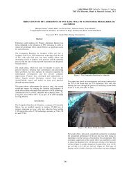
Phase II. A plant photo of the actual Phase II smelter is shown in<br />
Figure 1.<br />
The main advantage of a modular approach is that a smelter like<br />
Norðural can continue to grow at a steady pace. The rate of<br />
growth is determined by such factors as the availability of energy,<br />
capital and other constraints. Regarding the specific investment<br />
costs, a modular approach has the advantage of degressive<br />
investments, as parts of the infrastructure are already installed<br />
during the first construction stage.<br />
VAW Aluminium-Technology (VAW ATG) supplied the<br />
reduction technology for the Phase I Project. It is based on the<br />
state-of-the-art, side-by-side cell, operating at 180 kA (CA180/1).<br />
VAW ATG’s pot control system, ELAS, was also employed. The<br />
outstanding operational results of this first stage led to the owner’s<br />
decision to proceed with Phase II using the same technology.<br />
Consequently, 54 pots were to be commissioned. In addition, six<br />
fully graphitised cells, based on a refinement of the existing<br />
CA180/1 cell design, were to be installed in an integrated booster<br />
Norðurál, the Icelandic Saga Continues<br />
Detlef Vogelsang 1 , Joe Lombard 2 , Friedhelm Waldmann 1<br />
1 VAW Aluminium-Technologie GmbH<br />
P.O. Box 2468, D-53014 Bonn, Germany.<br />
2 Aluminerie Alouette Inc.<br />
CP 1650, Sept-Iles, Quebec, Canada<br />
section. The design amperage of these cells is 210 kA<br />
(CA180/2CA180/2). In the following, both cell types will be<br />
compared with regard to design and operational results.<br />
Figure 1: Plant photo of the Norðural Smelter Phase II<br />
Project Organisation<br />
Light Metals 2002<br />
Edited by Wolfgang Schneider<br />
TMS (The Minerals, Metals & Materials Society), 2002<br />
The Norðural Phase II Project was managed and executed by a<br />
team appointed by CVC. VAW ATG’s project team was fully<br />
integrated into this Norðural II team.<br />
VAW ATG performed several roles. It was the technology<br />
supplier for the CA180/1 and CA180/2 reduction cells and the<br />
supplier of key components, such as point feeder and dosing<br />
system as well as the pot control system and the six<br />
CA180/2CA180/2 superstructures. VAW ATG was also involved<br />
in direct contract negotiations for technology-related equipment<br />
and in quality assurance issues on-site and at the contractors’ sites<br />
for busbars (Venezuela) as well as pot shells and CA180/1<br />
superstructures (Dubai).<br />
Unlike in Phase I, where an expatriate engineering company<br />
conducted the EPCM activities, a local consortium of consulting<br />
engineers (HRV) - using the knowledge and experience they had<br />
gained then - handled all Phase II activities in co-operation with<br />
the CVC/ATG project team. By keeping bureaucracy and red tape<br />
to a minimum and by utilising short, efficient lines of<br />
communication, the project team was able to execute the project<br />
with pinpoint accuracy.
Planning for Phase II commenced after the stabilisation of Phase I<br />
in September 1999. Following the same development strategy,<br />
planning for the Phrase III expansion is now under the way after<br />
the stabilisation of Phase II.<br />
Site activities commenced in mid-February 2000. A busbar short<br />
circuit test was concluded on 26 May 2001 and start-up was<br />
completed on 17 July 2001.<br />
The project was thus completed six weeks ahead of schedule and<br />
within budget.<br />
Technological Aspects<br />
The reduction technology for the Phase II expansion of the<br />
Norðural smelter is based on the proven technology installed in<br />
Phase I. Details of this technology - the CA180/1 reduction cell<br />
with a rated amperage of 180 kA - are published elsewhere [1]. Of<br />
the 60 additional pots installed in Phase II, 54 cells are of the type<br />
CA180; 6 fully graphitised cells were also installed with a rated<br />
amperage of 210 kA<br />
The prime objective during the development of this cell was to<br />
achieve a reduction in the busbar and steel weights of at least 25<br />
%. The pot-to-pot distance also had to be decreased from 6.3 to<br />
5.9 m.<br />
The complete design of this cell was worked out from first<br />
principles on a clean sheet of paper. Hence, the potential for<br />
original, lateral thinking was not compromised by the need to use<br />
existing components or systems. The design was based on a<br />
proven set of busbar design tools and tools for the optimisation of<br />
the pot lining developed at VAW ATG. Features of these<br />
modelling instruments were published earlier [3,4,5]. The new pot<br />
shell was designed applying a fully 3-dimensional finite element<br />
model that takes the temperature distribution of the steel parts as<br />
predicted by thermo-electrical modelling into account.<br />
The CA180/2 refinement project was characterised by a<br />
concurrent engineering approach. After the definition of such<br />
basic data as the pot-to-pot distance, size of pot shell, layout of a<br />
first lining approach, an initial budget estimate was worked out.<br />
Using the preliminary modelling results from the conceptual<br />
designs of the busbar, superstructure, pot shell and lining<br />
available, the basic engineering of these components could<br />
commence and the tender drawings completed. This meant that<br />
the commercial aspect of tendering could begin with the enquiry<br />
for the various technology-related components. Revision loops<br />
ensured that improvements to the conceptual design were<br />
integrated into the final detailed engineering of the CA180/2. By<br />
the time the tenders were ready for awarding, the final<br />
manufacturing drawings were issued and any modifications<br />
included in the final contract negotiations.<br />
Concurrent activities in all fields of modelling, engineering and<br />
commerce resulted in a total fast-track development time of only<br />
15 months for this new cell technology.<br />
A computer model of the CA180/2 cell is shown in Figure 2.<br />
Figure 2: Computer model of the CA180/2 cell<br />
The busbar system was optimised with respect to weight and<br />
voltage drop. A four-riser solution was formulated to give a potto-pot<br />
distance of 5.9 m for the CA180/2 cells compared with 6.3<br />
m for the CA180/1 cells used in Phase I. The weight of aluminium<br />
required for the busbar system decreased from 36.6 to 21.7 t. The<br />
voltage drop for the external busbar system was reduced by 20<br />
mV. Due to the position of the risers, the theoretical width of the<br />
potroom building was reduced by 1.3 m. The cost of installing the<br />
busbar system was cut by having major parts of the busbar ring<br />
system prefabricated in workshops and supplied to the<br />
construction site as subassemblies.<br />
Magneto-hydrodynamic computations indicated an improved<br />
magneto-hydrodynamic stability for the CA180/2 compared with<br />
that of the CA180/1 operating at a 30 kA lower amperage. The<br />
smooth start-up of the CA180/2 fully graphitised cells confirmed<br />
these theoretical predictions. Metal and bath velocities increased<br />
slightly but had no impact on the practical pot performance and<br />
heat transfer at the long side of the pot. The crossover of the<br />
busbar at the end of both potrooms as well as the positioning of<br />
the booster rectifier for the CA180/2 fully graphitised cells was<br />
optimised with regard to the magnetic field conditions for the end<br />
cells and the neighbouring CA180/1 cells.<br />
The cathode design is characterised by fully graphitised twin<br />
cathode blocks. The four collector bars per cathode element are<br />
cast iron rodded. Compared with the CA180/1 lining, the height of<br />
the bottom insulation was reduced, which means that the CA180/2<br />
pot shell is 100 mm lower than its CA180/1 counterpart.<br />
The predicted cell voltage based on the thermo-electrical model<br />
[3] was 4.2 V; the predicted current efficiency was 95 %. Both<br />
figures were verified by the operational results achieved during<br />
the first three months of pot operation.<br />
The pot shell was optimised to give low weight, high stiffness and<br />
optimal ventilation of the cooling ambient airflow. As published<br />
earlier [7], cooling fins were employed to give improved heat<br />
transfer and higher stiffness of the shell sidewalls. The ventilation<br />
of the pot shells was further improved by the installation of floor<br />
grids around the periphery of the pot stall. Compared with the
CA180, fewer cradles were required since twin cathode blocks<br />
were installed. The installation of welded cradles together with<br />
improved bracing of the short ends of the shell resulted in a pot-<br />
The same anode assembly as used for the CA180/1 was<br />
employed. The design principles of the superstructure, however,<br />
are novel. The anode-jacking system was constructed as a<br />
scissor jacking system, see Figure 4. This resulted in a<br />
significant reduction in the anode beam weight.<br />
A second positive effect is the reduction in the height of the<br />
potroom building that will be achievable in the Phase III project.<br />
The hopper/point-feeder system comprises three alumina<br />
hoppers with pneumatically operated crust breakers and dosing<br />
valves and one hopper for aluminium fluoride. A feedback<br />
signal to the ELAS pot control system is used to indicate a<br />
successful breaking operation [6] and supply other essential<br />
operational information to ensure early fault detection and<br />
reliable dosing of alumina. The breaker units are height<br />
adjustable and easily adapted to different bath level heights.<br />
Expanding the potlines by 60 reduction cells also called for<br />
enhanced pot-tending equipment. Using an advanced logistics<br />
Figure 3: Loading forces for the CA180/2 pot shell<br />
shell weight reduction of 30%. Despite this, the load bearing<br />
capacity of the shell was increased by a factor of 1.8. A FEM<br />
result for the loading forces is shown in Figure 3.<br />
model [2], which incorporated detailed smelter logistics, VAW<br />
ATG investigated various alternatives for pot-tending<br />
equipment. The most reliable and economical solution turned<br />
out to be the installation of a dense-phase system for supplying<br />
alumina throughout the whole Norðural smelter, together with<br />
an additional crane for pot tending. An additional gantry at the<br />
end of the extended potrooms also improved the traffic load and<br />
flow.<br />
The smelter’s power supply was sufficient for the increased<br />
number of reduction cells. Only an additional seawater-cooling<br />
loop had to be installed. The anode-rodding shop also had<br />
sufficient capacity for the increased production. The casthouse<br />
was equipped with an additional 70-t holding furnace as well as<br />
a 12-t/h sow caster carousel. Besides the civil engineering works<br />
for the extended potrooms, a 6-bay lining shop was also<br />
installed. It is insulated and heated to create “normal”<br />
temperature conditions especially for winter lining operations.
This lining shop proved invaluable time and time again during<br />
the lining phase.<br />
Figure 4: Plant photo of the CA180/2 cell at Norðural<br />
Start-up and Early Operations<br />
Both the CA180/1 and CA180/2 pots were started up under full<br />
current load. A graphite resistor bed was placed underneath the<br />
anodes. Typical preheating times were 72 hours. Besides regular<br />
control of the CA180/1 cells, an extended and comprehensive<br />
measurement programme was carried out on the CA180/2 fully<br />
graphitised cells. During preheating, cathode temperature,<br />
current pick-up of the anodes and anodic risers were measured at<br />
2-hour intervals. Strain gauge measurements were conducted on<br />
the pot shells and superstructures.<br />
After bath addition and start-up, the cathodic current distribution<br />
and anodic riser currents were determined every 12 hours. A<br />
typical preheating result is shown in Figure 5.<br />
Due to the decreasing electrical resistance of the fully<br />
graphitised cathodes, the average heating rate as measured on<br />
the top surface of the cathodes, decreased from 25°/h to about<br />
5°/h. It was seen that the CA180/2 cells, equipped with fully<br />
graphitised cathodes, are much more sensitive to variations<br />
during start-up than the amorphous cathode of the CA180/1<br />
pots. Hence, tight control during this critical period of cell life is<br />
extremely important.<br />
The operational data obtained during the first three months of<br />
operation have been encouraging with a current efficiency of<br />
95% and a specific D.C. energy consumption of 13.1 kWh/t Al.<br />
Anode effect frequencies have been as low as 0.03/pot day. The<br />
ELAS pot control system together with the sophisticated point<br />
breaker/feeder system have achieved success rates of 75% for<br />
extinguishing anode effects.<br />
60<br />
50<br />
40<br />
30<br />
20<br />
10<br />
0<br />
-10<br />
3<br />
6<br />
9<br />
12<br />
Figure 5: Typical preheating for the CA180/2 cell.<br />
Conclusions<br />
The modular approach of building a greenfield aluminium<br />
smelter phase by phase has proved to be successful. The specific<br />
investment costs are substantially lower than those of a fullsized<br />
smelter investment. The planning of the expansion steps<br />
can also be adjusted to external constraints, such as availability<br />
of energy and capital.<br />
The development concept and project strategy for the new<br />
CA180/2 cell demonstrated that the bundling of computer<br />
models for the conceptual design with novel approaches for<br />
engineered solutions could result in very low investment costs.<br />
The concept of concurrent engineering with revision loops<br />
helped to reduce the development time to only 15 months.<br />
In addition, this new VAW CA180/2 reduction cell provided<br />
outstanding operational results at the first attempt.<br />
References<br />
15<br />
18<br />
21<br />
24<br />
27<br />
30<br />
33<br />
A086<br />
36<br />
39<br />
dT/hr ave<br />
1. Joe Lombard, “Norðural: A Fast-Track Modular Smelter”,<br />
Light Metals 1999, pp. 159-163.<br />
2. Ingo Eick, Detlef Vogelsang, Andrae Behrens, “Planning<br />
Smelter Logistics: A Process Modeling Approach”, Light<br />
Metals 2001, pp. 393-398.<br />
3. Detlef Vogelsang, Ingo Eick, Martin Segatz, Christian<br />
Droste, “From 110 to 175 kA: Retrofit of VAW Rheinwerk,<br />
Part I: Modernisation Concept”, Light Metals 1997, pp.<br />
233-238.<br />
4. Detlef Vogelsang, “Application of Integrated Simulation<br />
Tools for Retrofitting Aluminium Smelters”, 4 th<br />
Australasian Aluminium Smelter Technology Workshop,<br />
25-30 October 1992, pp. 641-643.<br />
5. Martin Segatz, Christian Droste, “Analysis of Magnetohydrodynamic<br />
Instabilities in Aluminium Reduction Cells”,<br />
Light Metals 1994, pp. 313-322.<br />
6. Klaus Hofenbitzer, “Improved Concept of Alumina<br />
Feeding”, Light Metals 1999, pp. 293-296.<br />
7. Ingo Eick, Detlef Vogelsang, “Dimensioning of Cooling<br />
Fins for High-Amperage Reduction Cells”, Light Metals<br />
1999, pp. 339-345.<br />
42<br />
45<br />
48<br />
51<br />
54<br />
57<br />
60<br />
63<br />
66<br />
69<br />
72<br />
1100<br />
1000<br />
900<br />
800<br />
700<br />
600<br />
500<br />
400<br />
300<br />
200<br />
100