M1 intake manifold install - RM Indy
M1 intake manifold install - RM Indy
M1 intake manifold install - RM Indy
You also want an ePaper? Increase the reach of your titles
YUMPU automatically turns print PDFs into web optimized ePapers that Google loves.
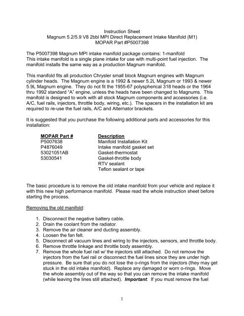
Instruction Sheet<br />
Magnum 5.2/5.9 V8 2bbl MPI Direct Replacement Intake Manifold (<strong>M1</strong>)<br />
MOPAR Part #P5007398<br />
The P5007398 Magnum MPI <strong>intake</strong> <strong>manifold</strong> package contains: 1-<strong>manifold</strong><br />
This <strong>intake</strong> <strong>manifold</strong> is a single plane <strong>intake</strong> for use with multi-point fuel injection. The<br />
<strong>manifold</strong> <strong>install</strong>s the same way as a production Magnum <strong>manifold</strong>.<br />
This <strong>manifold</strong> fits all production Chrysler small block Magnum engines with Magnum<br />
cylinder heads. The Magnum engine is a 1992 & newer 5.2L Magnum or 1993 & newer<br />
5.9L Magnum engine. They do not fit the 1955-67 polyspherical 318 heads or the 1964<br />
thru 1992 standard “A” engine, unless the heads have been changed to Magnums. This<br />
<strong>manifold</strong> is designed to work with all stock Magnum components and accessories (i.e.<br />
A/C, fuel rails, injectors, throttle body, wiring, etc.). The spacers in the <strong>install</strong>ation kit are<br />
required to re-use the fuel rails, A/C and Alternator brackets.<br />
It is suggested that you purchase the following additional parts and accessories for this<br />
<strong>install</strong>ation:<br />
MOPAR Part #<br />
Description<br />
P5007638<br />
Manifold Installation Kit<br />
P4876049<br />
Intake <strong>manifold</strong> gasket set<br />
53021051AB<br />
Gasket-thermostat<br />
53030541 Gasket-throttle body<br />
RTV sealant<br />
Teflon sealant or tape<br />
The basic procedure is to remove the old <strong>intake</strong> <strong>manifold</strong> from your vehicle and replace it<br />
with this new high performance <strong>manifold</strong>. Please read the whole instruction sheet before<br />
starting the process.<br />
Removing the old <strong>manifold</strong>:<br />
1. Disconnect the negative battery cable.<br />
2. Drain the coolant from the radiator.<br />
3. Remove the air cleaner and ducting assembly.<br />
4. Loosen the fan felt.<br />
5. Disconnect all vacuum lines and wiring to the injectors, sensors, and throttle body.<br />
6. Remove throttle linkage and throttle body assembly.<br />
7. Remove the whole fuel rail w/ the injectors still attached. Do not remove the<br />
injectors from the fuel rail or disconnect the fuel lines since they are under high<br />
pressure. Be sure that you do not lose the o-rings from the injectors (they may get<br />
stuck in the old <strong>intake</strong> <strong>manifold</strong>). Replace any damaged or worn o-rings. Move<br />
the whole assembly out of the way so that you can remove the <strong>intake</strong> <strong>manifold</strong><br />
(while leaving the lines still attached). Important: If you must remove the fuel<br />
1
lines be sure to release the fuel pressure in the system (please see the service<br />
manual for the procedure for your vehicle).<br />
8. Remove the alternator and A/C compressor and the brackets that attach them to<br />
the <strong>intake</strong> <strong>manifold</strong> / Cylinder Heads / Block. Do not remove the A/C lines since<br />
this will allow the A/C charge to escape into the atmosphere. Move the A/C<br />
compressor off to the side so that you can work on the <strong>manifold</strong> (with A/C lines still<br />
attached).<br />
9. Remove the heater hose, by-pass hose, wiring, and EGR tube (if your vehicle has<br />
EGR), and thermostat housing / thermostat.<br />
10. Remove the old <strong>intake</strong> <strong>manifold</strong>. It may be necessary to remove one valve cover<br />
if you have the aluminum die cast MOPAR performance valve covers.<br />
Installation:<br />
1. Transfer the following components over from the old <strong>intake</strong> <strong>manifold</strong> to the new one<br />
before it is <strong>install</strong>ed on the engine (by-pass nipple, heater hose nipple, air charge<br />
temp. sensor, EGR valve, coolant temp. sensor(s), thermostat & housing, and EGR<br />
valve). You may need to use some of the adapters included in the <strong>install</strong>ation kit<br />
(P5007638) in some applications. Use a new gasket on the thermostat housing.<br />
Seal the pipe threads on the sensors and fittings with Teflon seal tape or Teflon<br />
sealant.<br />
2. The air charge temp sensor has been relocated to a new position on the new<br />
<strong>manifold</strong>. The sensor must be screwed into the tapped hole in the front of the<br />
<strong>manifold</strong> plenum (the old location in the stock production <strong>manifold</strong> was in the runner<br />
for the #2 cylinder). This sensor was relocated to reduce the restriction in airflow in<br />
the runner.<br />
3. Plug any extra coolant holes in the <strong>intake</strong> <strong>manifold</strong> with the plugs included in the<br />
<strong>install</strong>ation kit (P5007638). Some applications will use all of the threaded holes in<br />
the <strong>manifold</strong> and others will have an extra hole or two which must be plugged.<br />
4. If your vehicle has an EGR system (1992 to 1996 vehicles), <strong>install</strong> a ½ inch NPT<br />
pipe plug in the tapped hole in the cast passage about midway between the EGR<br />
valve and the plenum of the <strong>manifold</strong>. Use Teflon seal tape or sealant on the<br />
threads of this plug.<br />
5. If your vehicle does not have an EGR system (1997 & up vehicles) <strong>install</strong> a ½ inch<br />
NPT plug in the tapped hole in the bottom of the plenum. Use Teflon seal tape or<br />
sealant on the threads of this plug. Note: you must <strong>install</strong> this plug in one of the<br />
two locations described above. Failure to <strong>install</strong> this plug will create a very large<br />
vacuum leak or EGR leak. Be sure to <strong>install</strong> this plug before you <strong>install</strong> the<br />
<strong>manifold</strong> on the engine since you don’t want to accidentally drop the plug into one<br />
of the <strong>intake</strong> passages.<br />
6. Prior to <strong>install</strong>ing the new <strong>intake</strong> <strong>manifold</strong>, clean all of the mating surfaces to<br />
remove and old gasket material and all grease and oil. Place approximately a ¼<br />
inch bead of silicone gasket sealer in the 4 “corners” where the end seals meet the<br />
paper gaskets.<br />
7. Set the 4 <strong>intake</strong> gaskets in place on the clean block. On the two side gaskets, the<br />
words “Manifold Side” should be visible on both and the tabs on the <strong>manifold</strong><br />
2
gasket should fit in with the tabs on the head gasket. The front seal is basically<br />
straight and the rear seal has a big hook in it. They fit on the front and rear block<br />
crossovers.<br />
8. Carefully place the <strong>intake</strong> <strong>manifold</strong> into position on the engine. Use a five-step<br />
procedure to torque the <strong>intake</strong> bolts in steps up to 12 ft-lbs. See Figure for<br />
sequence. Caution: Do NOT over torque – over tightening the bolts can cause<br />
the heads to crack, sealing problems, or other failures.<br />
9. Apply small amount of clean engine oil to each fuel injector o-ring.<br />
10. Position the fuel rail/fuel injector assembly to injector openings on <strong>intake</strong> <strong>manifold</strong>.<br />
11. Guide each injector into <strong>intake</strong> <strong>manifold</strong>. Be careful not to damage the injector o-<br />
rings.<br />
12. Push right fuel rail down until fuel injectors have bottomed on injector shoulder.<br />
Push left fuel rail down until fuel injectors have bottomed on injector shoulder.<br />
13. Use the tubular spacers and 5/16” screws included in the <strong>install</strong>ation kit (P5007638)<br />
to connect the fuel rail to the <strong>manifold</strong>. Three tubular spacers are used between<br />
the fuel rail brackets and the bosses on the <strong>intake</strong> <strong>manifold</strong>. One common spacer<br />
(w/ two holes in it) is used in the front of the <strong>manifold</strong> on the passenger side to hold<br />
the fuel rail and the alternator support rod. You may have to pull the fuel rails up<br />
slightly to insert the spacers. Tighten all of the 5/16” long screws holding fuel rail to<br />
20 ft-lbs.<br />
14. Re-connect the wiring to the <strong>manifold</strong> air temperature sensor. The sensor has<br />
been re-located to the front of the plenum and will require that the wiring be<br />
extended about 12”. Cut off the old connector and splice in an extension to reach<br />
the new location of the sensor (reuse the connector w/ the extension). The<br />
<strong>install</strong>ation kit (P5007638) includes the needed wire, connectors, and shrink sleeve<br />
to modify the wiring harness.<br />
15. Connect the wiring to all injectors. The injector wiring harness is numerically<br />
tagged to show the proper cylinder.<br />
16. Re-connect the EGR, heater hose, and coolant by-pass hose, wiring to the coolant<br />
temp. sensor(s) and vacuum lines. Re-route any vacuum lines were needed.<br />
17. Plug any of the extra vacuum nipples on the <strong>intake</strong> <strong>manifold</strong> w/ the plugs in the<br />
<strong>install</strong>ation kit.<br />
18. Re-<strong>install</strong> alternator and A/C compressor and brackets. Use the long 3/8” screw<br />
included in the <strong>install</strong>ation kit for the alternator support rod (this goes through the<br />
common spacer w/ 2 holes in it). Re-<strong>install</strong> the A/C bracket and use the remaining<br />
short tubular spacer to attach this bracket to the <strong>intake</strong> <strong>manifold</strong> w/ the 5/16” screw.<br />
Re-<strong>install</strong> the fan belt.<br />
19. Install throttle body to <strong>intake</strong> <strong>manifold</strong>. Replace the gasket if it is damaged. Torque<br />
the 4 mounting screws to 17 ft-lbs. Reconnect the wiring to the throttle body.<br />
20. Reconnect the throttle linkage. Check the linkage for smooth operation and make<br />
sure it does not bind or interfere with any wiring or vacuum lines.<br />
21. Refill the cooling system with anti-freeze (50/50 mixture)<br />
22. Install air cleaner.<br />
23. Check hood clearance (the new <strong>manifold</strong> is the same height as the stock <strong>manifold</strong>,<br />
so this should not be a problem).<br />
24. Reconnect battery cable.<br />
3
25. Start it up and check for leaks<br />
Intake <strong>manifold</strong> bolt tightening sequence<br />
12 8 3 1 5<br />
9<br />
Front of Engine<br />
T-stat<br />
11 7 4 2 6 10<br />
4


