Adding Grayscale Layer to Chrome Photomasks - Professor Glenn ...
Adding Grayscale Layer to Chrome Photomasks - Professor Glenn ...
Adding Grayscale Layer to Chrome Photomasks - Professor Glenn ...

You also want an ePaper? Increase the reach of your titles
YUMPU automatically turns print PDFs into web optimized ePapers that Google loves.
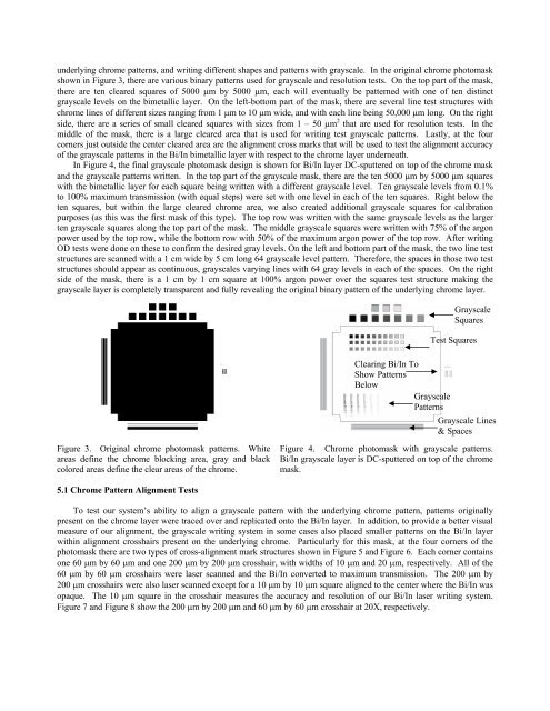
underlying chrome patterns, and writing different shapes and patterns with grayscale. In the original chrome pho<strong>to</strong>mask<br />
shown in Figure 3, there are various binary patterns used for grayscale and resolution tests. On the <strong>to</strong>p part of the mask,<br />
there are ten cleared squares of 5000 µm by 5000 µm, each will eventually be patterned with one of ten distinct<br />
grayscale levels on the bimetallic layer. On the left-bot<strong>to</strong>m part of the mask, there are several line test structures with<br />
chrome lines of different sizes ranging from 1 µm <strong>to</strong> 10 µm wide, and with each line being 50,000 µm long. On the right<br />
side, there are a series of small cleared squares with sizes from 1 – 50 µm 2 that are used for resolution tests. In the<br />
middle of the mask, there is a large cleared area that is used for writing test grayscale patterns. Lastly, at the four<br />
corners just outside the center cleared area are the alignment cross marks that will be used <strong>to</strong> test the alignment accuracy<br />
of the grayscale patterns in the Bi/In bimetallic layer with respect <strong>to</strong> the chrome layer underneath.<br />
In Figure 4, the final grayscale pho<strong>to</strong>mask design is shown for Bi/In layer DC-sputtered on <strong>to</strong>p of the chrome mask<br />
and the grayscale patterns written. In the <strong>to</strong>p part of the grayscale mask, there are the ten 5000 µm by 5000 µm squares<br />
with the bimetallic layer for each square being written with a different grayscale level. Ten grayscale levels from 0.1%<br />
<strong>to</strong> 100% maximum transmission (with equal steps) were set with one level in each of the ten squares. Right below the<br />
ten squares, but within the large cleared chrome area, we also created additional grayscale squares for calibration<br />
purposes (as this was the first mask of this type). The <strong>to</strong>p row was written with the same grayscale levels as the larger<br />
ten grayscale squares along the <strong>to</strong>p part of the mask. The middle grayscale squares were written with 75% of the argon<br />
power used by the <strong>to</strong>p row, while the bot<strong>to</strong>m row with 50% of the maximum argon power of the <strong>to</strong>p row. After writing<br />
OD tests were done on these <strong>to</strong> confirm the desired gray levels. On the left and bot<strong>to</strong>m part of the mask, the two line test<br />
structures are scanned with a 1 cm wide by 5 cm long 64 grayscale level pattern. Therefore, the spaces in those two test<br />
structures should appear as continuous, grayscales varying lines with 64 gray levels in each of the spaces. On the right<br />
side of the mask, there is a 1 cm by 1 cm square at 100% argon power over the squares test structure making the<br />
grayscale layer is completely transparent and fully revealing the original binary pattern of the underlying chrome layer.<br />
<strong>Grayscale</strong><br />
Squares<br />
Test Squares<br />
Clearing Bi/In To<br />
Show Patterns<br />
Below<br />
<strong>Grayscale</strong><br />
Patterns<br />
<strong>Grayscale</strong> Lines<br />
& Spaces<br />
Figure 3. Original chrome pho<strong>to</strong>mask patterns. White<br />
areas define the chrome blocking area, gray and black<br />
colored areas define the clear areas of the chrome.<br />
Figure 4. <strong>Chrome</strong> pho<strong>to</strong>mask with grayscale patterns.<br />
Bi/In grayscale layer is DC-sputtered on <strong>to</strong>p of the chrome<br />
mask.<br />
5.1 <strong>Chrome</strong> Pattern Alignment Tests<br />
To test our system’s ability <strong>to</strong> align a grayscale pattern with the underlying chrome pattern, patterns originally<br />
present on the chrome layer were traced over and replicated on<strong>to</strong> the Bi/In layer. In addition, <strong>to</strong> provide a better visual<br />
measure of our alignment, the grayscale writing system in some cases also placed smaller patterns on the Bi/In layer<br />
within alignment crosshairs present on the underlying chrome. Particularly for this mask, at the four corners of the<br />
pho<strong>to</strong>mask there are two types of cross-alignment mark structures shown in Figure 5 and Figure 6. Each corner contains<br />
one 60 µm by 60 µm and one 200 µm by 200 µm crosshair, with widths of 10 µm and 20 µm, respectively. All of the<br />
60 µm by 60 µm crosshairs were laser scanned and the Bi/In converted <strong>to</strong> maximum transmission. The 200 µm by<br />
200 µm crosshairs were also laser scanned except for a 10 µm by 10 µm square aligned <strong>to</strong> the center where the Bi/In was<br />
opaque. The 10 µm square in the crosshair measures the accuracy and resolution of our Bi/In laser writing system.<br />
Figure 7 and Figure 8 show the 200 µm by 200 µm and 60 µm by 60 µm crosshair at 20X, respectively.