BOB REVOLUTION OWNER'S MANUAL - BOB Trailers and Strollers
BOB REVOLUTION OWNER'S MANUAL - BOB Trailers and Strollers
BOB REVOLUTION OWNER'S MANUAL - BOB Trailers and Strollers

Create successful ePaper yourself
Turn your PDF publications into a flip-book with our unique Google optimized e-Paper software.
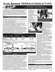
(800) 893-2447 www.bobgear.com email- info@bobgear.com<br />
Phone: (208) 375-5171 Fax: (208) 375-5172, <strong>BOB</strong> <strong>Trailers</strong>, Inc. 5475 Gage St. Boise, Idaho 83706<br />
MA0606<br />
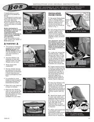
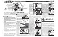
release adjusting<br />
nut (Fig. 4) by h<strong>and</strong>.<br />
Re-insert the axle<br />
fully into the rear<br />
dropout until the<br />
axle shoulder or<br />
snap ring on the<br />
axle comes in<br />
contact with the<br />
dropout (Fig. 5).<br />
Move the quick<br />
release lever to the<br />
closed position (Fig.<br />
6). The word<br />
CLOSE should be<br />
clearly visible <strong>and</strong><br />
the quick release<br />
lever should almost<br />
touch the dropout.<br />
When properly<br />
adjusted, it will<br />
require<br />
considerable torque<br />
(80-105 in-lbs or 9-<br />
12 Nm) to close the<br />
lever. If you do not<br />
feel this resistance<br />
Insert<br />
Wheel<br />
Fully<br />
(too loose or too tight), return the quick release lever back to the open<br />
position (Fig. 4), <strong>and</strong> adjust the adjusting nut (clockwise to tighten,<br />
counterclockwise to loosen). Move the quick release lever to the<br />
closed position (Fig. 6).<br />
NOTE: Follow all instructions exactly. If you are unsure how to operate<br />
the quick release, consult your<br />
dealer or contact <strong>BOB</strong>.<br />
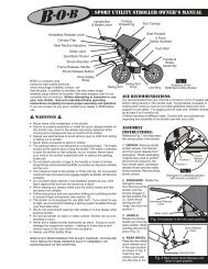
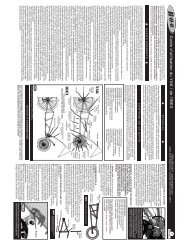
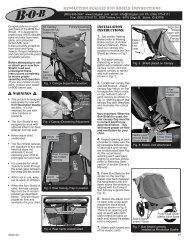
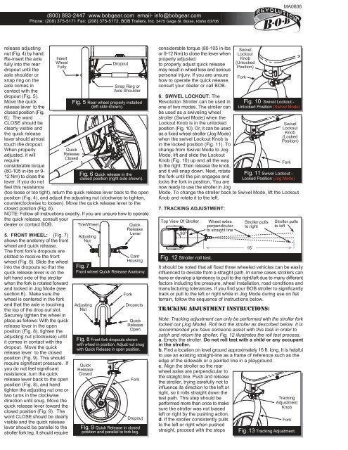
5. FRONT WHEEL: (Fig. 7)<br />
shows the anatomy of the front<br />
wheel <strong>and</strong> quick release.<br />
The front fork’s dropouts are<br />
slotted to receive the front<br />
wheel (Fig. 8). Slide the wheel<br />
into the dropouts so that the<br />
quick release lever is on the<br />
left h<strong>and</strong> side of the stroller<br />
when the fork is rotated forward<br />
<strong>and</strong> locked in Jog Mode (see<br />
section 6). Make sure the<br />
wheel is centered in the fork<br />
<strong>and</strong> that the axle is touching<br />
the top of the drop out slot.<br />
Securely tighten the wheel in<br />
place as follows: With the quick<br />
release lever in the open<br />
position (Fig. 8), tighten the<br />
adjusting nut (clockwise) until<br />
it comes in contact with the<br />
dropout. Move the quick<br />
release lever to the closed<br />
position (Fig. 9). This should<br />
require significant pressure. If<br />
you do not feel significant<br />
resistance, turn the quick<br />
release lever back to the open<br />
position (Fig. 8), <strong>and</strong> h<strong>and</strong><br />
tighten the adjusting nut one or<br />
two turns in the clockwise<br />
direction until snug. Move the<br />
quick release lever toward the<br />
closed position (Fig. 9). The<br />
word CLOSE should be clearly<br />
visible <strong>and</strong> the quick release<br />
lever should be parallel to the<br />
stroller fork leg. It should require<br />
Quick<br />
Release<br />
Closed<br />
Tire/Wheel<br />
Adjusting<br />
Nut<br />
Dropout<br />
Snap Ring or<br />
Axle Shoulder<br />
Fig. 5 Rear wheel properly installed<br />
(left side shown).<br />
Fig. 6 Quick release in the<br />
closed position (right side shown).<br />
Quick<br />
Release<br />
Lever<br />
Cam<br />
Housing<br />
Fig. 7<br />
Front wheel Quick Release Anatomy.<br />
Adjusting<br />
Nut<br />
Fig. 8 Front fork dropouts shown<br />
with wheel in position. Adjust nut snug<br />
with Quick Release in open position.<br />
Quick<br />
Release<br />
Closed<br />
Fork<br />
Dropouts<br />
Quick<br />
Release<br />
Open<br />
Fork<br />
Dropout<br />
Fig. 9 Quick Release in closed<br />
position <strong>and</strong> parallel to fork leg.<br />
considerable torque (80-105 in-lbs<br />
or 9-12 Nm) to close the lever when<br />
properly adjusted.<br />
to properly adjust quick release<br />
may result in wheel loss <strong>and</strong> serious<br />
personal injury. If you are unsure<br />
how to operate the quick release,<br />
consult your dealer or call <strong>BOB</strong>.<br />
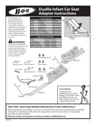
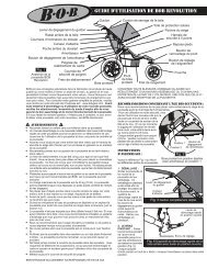
6. SWIVEL LOCKOUT: The<br />
Revolution Stroller can be used in<br />
one of two modes. The stroller can<br />
be used as a swiveling wheel<br />
stroller (Swivel Mode) when the<br />
Lockout Knob is in the unlocked<br />
position (Fig. 10). Or, it can be used<br />
as a fixed wheel stroller (Jog Mode)<br />
when the swivel Lockout Knob is<br />
in the locked position (Fig. 11). To<br />
change from Swivel Mode to Jog<br />
Mode, lift <strong>and</strong> slide the Lockout<br />
Knob (Fig. 10) up <strong>and</strong> all the way<br />
to the right. Then release the knob,<br />
<strong>and</strong> it will snap down. Next, rotate<br />
the fork until the pin engages <strong>and</strong><br />
locks the fork in position. You are<br />
now ready to use the stroller in Jog<br />
Mode. To change the stroller back to Swivel Mode, lift the Lockout<br />
Knob <strong>and</strong> rotate it to the left.<br />
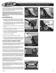
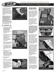
7. TRACKING ADJUSTMENT:<br />
Top View Of Stroller Wheel axles<br />
perpendicular<br />
90 o to straight line<br />
Fig. 12 Stroller roll test.<br />
It should be noted that all fixed three wheeled vehicles can be easily<br />
influenced to deviate from a straight path. In some cases strollers can<br />
have or develop a tendency to pull to the right/left due to many different<br />
factors including tire pressure, wheel installation, road conditions <strong>and</strong><br />
manufacturing tolerances. If you find your <strong>BOB</strong> stroller to significantly<br />
track or pull to the left or right while in Jog Mode during use on flat<br />
terrain, follow the sequence of instructions below.<br />
Tracking Adjustment Instructions:<br />
Note: Tracking adjustment can only be performed with the stroller fork<br />
locked out (Jog Mode). Roll test the stroller as described below. It is<br />
recommended you have someone assist with this task in order to<br />
catch <strong>and</strong> return the stroller. Fig. 12 illustrates the roll test process.<br />
a. Empty the stroller. Do not roll test with a child or any occupant<br />
in the stroller.<br />
b. Find a location on level ground approximately 16 ft. long. It is helpful<br />
to use an existing straight-line as a frame of reference such as the<br />
edge of the sidewalk or a painted line in a playground.<br />
c. Align the stroller so the rear<br />
wheel axles are perpendicular to<br />
the straight line. Push <strong>and</strong> release<br />
the stroller, trying carefully not to<br />
influence its direction to the left or<br />
right, so it rolls straight down the<br />
test path. This step should be<br />
performed more than once to make<br />
sure the stroller was not biased<br />
left or right by the pushing action.<br />
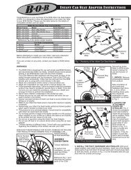
d. If the stroller consistently pulls<br />
to the left or right when pushed<br />
straight, proceed with the steps<br />
Swivel<br />
Lockout<br />
Knob<br />
(Unlocked<br />
Position)<br />
Fork<br />
Fig. 10 Swivel Lockout -<br />
Unlocked Position (Swivel Mode)<br />
Fig. 11 Swivel Lockout -<br />
Locked Position (Jog Mode)<br />
Stroller pulls<br />
to right<br />
16’<br />
Swivel<br />
Lockout<br />
Knob<br />
(Locked<br />
Position)<br />
Fork<br />
Stroller pulls<br />
to left<br />
Tracking<br />
Adjustment<br />
Knob<br />
Fork<br />
Fig. 13 Tracking Adjustment.