
Create successful ePaper yourself
Turn your PDF publications into a flip-book with our unique Google optimized e-Paper software.
YAK/IBEX OWNER’S MANUAL<br />
(800) 893-2447 www.bobgear.com<br />
13501 South Ridge Drive, Charlotte, North Carolina 28273<br />
1<br />
OMT01C<br />
<strong>BOB</strong> is a company that produces high quality products, which encourage a healthy, outdoor,<br />
car-free lifestyle. In addition to trailers, we also make full suspension jogging strollers. See<br />
www.bobgear.com for our complete line of products. Before attempting to assemble or use<br />
your new trailer, read <strong>and</strong> underst<strong>and</strong> these instructions completely to insure proper<br />
assembly <strong>and</strong> operation. If you are unclear on any point, contact your dealer or <strong>BOB</strong> before<br />
use.<br />
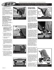
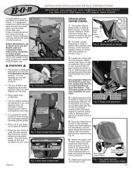
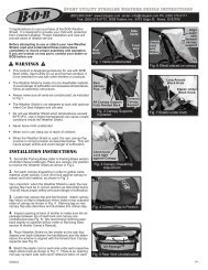
WARNINGS<br />
• <strong>BOB</strong> trailers can be attached to bicycles with wheel sizes between 20" <strong>and</strong> 28". Please see<br />
the Trailer/Bike Compatibility chart at the end of this manual to determine which trailer is<br />
compatible with your bike. The wheel size appears as a raised surface on the side-wall of the<br />
bicycle tire. If your wheels do not meet these diameter specifications, it is unsafe for you to<br />
attach the trailer. If you have questions about your wheel diameters or trailer compatibility with<br />
your bicycle, consult your bicycle dealer or call us at <strong>BOB</strong>.<br />
• Our trailers are intended to carry cargo only.<br />
• Do not carry children or live animals.<br />
• Cargo capacity: 70 pounds (32 kilograms)<br />
• The more weight you add to the trailer, (just like a car) the more effect it will have on the<br />
h<strong>and</strong>ling of your bicycle.<br />
• All cargo must be securely fastened to the trailer frame. Shifting loads can adversely affect<br />
bicycle h<strong>and</strong>ling <strong>and</strong> result in loss of control.<br />
• Keep the cargo center of gravity low.<br />
• The load height above the mesh platform should never exceed 18 inches (46cm). Loads<br />
higher than 18" can adversely affect bicycle h<strong>and</strong>ling <strong>and</strong> result in loss of control.<br />
• QR length must be correctly sized to your specific bicycle to insure safe operation.<br />
• Make sure your bike's brakes are in top condition <strong>and</strong> properly adjusted. Always allow extra<br />
stopping distance when riding with your trailer. Marginally performing brakes will be inadequate<br />
for safe braking with the added load of a trailer. When riding in wet conditions use extreme<br />
caution <strong>and</strong> allow even more distance for braking.<br />
• Generally, car drivers don't expect bicycles to be pulling trailers. Use the included <strong>BOB</strong><br />
safety flag to be seen!<br />
• When passing another cyclist, remember that you are approximately 4.5 feet (140cm) longer<br />
than your bike alone!<br />
• The YAK & IBEX come with wheel <strong>and</strong> fender reflectors for night visibility. Check that the<br />
reflectors on both your bicycle <strong>and</strong> trailer are properly installed. Installation procedures follow<br />
in this manual. Contact your appropriate state government office to learn of the lighting<br />
requirements for your state / country.<br />
• SPEED LIMIT: 25 mph (40 kph) A bike with trailer attached, steers <strong>and</strong> feels different.<br />
Ride cautiously. Speed wobbles (<strong>and</strong> loss of control) can occur if speed limit is exceeded.<br />
• It is CRITICAL that the wheels <strong>and</strong> tires of your bicycle <strong>and</strong> trailer are properly maintained<br />
(see your bike dealer) <strong>and</strong> inflated to the normal operating pressure embossed on the sidewall.<br />
• Some full suspension bicycles <strong>and</strong> rear suspension recumbents do not have adequate frame<br />
stiffness to offset the forces of a fully loaded, moving trailer. The result can be a bike that is<br />
sluggish, difficult to control or stop which could lead to a crash (<strong>and</strong>/or damage to the trailer<br />
or contents). We strongly recommend test riding (braking <strong>and</strong> turning) the bike with a full,<br />
non-human, test load [70 lbs (32kgs)] in a cautious manner (in an area absent of traffic hazards)<br />
to determine if this condition exists. This condition could be exacerbated by wet, s<strong>and</strong>y, or<br />
gravel covered surfaces.<br />
• Some variables that can affect the control of your bike <strong>and</strong> trailer: improper installation of<br />
<strong>BOB</strong> QR / improper installation of trailer fork retaining pins to <strong>BOB</strong> QR / improper installation<br />
of trailer fork to YAK & IBEX frame / road conditions / wind speed <strong>and</strong> direction / cyclist's skill<br />
level / weight of rider relative to the amount of weight in trailer / center of gravity of cargo /<br />
integrity of all wheels (proper spoke tension <strong>and</strong> bearing adjustment)<br />
• Rear racks <strong>and</strong> panniers are sometimes used in conjunction with the trailers. With some<br />
frames (usually smaller sizes) it is possible for the bottom of the pannier to come in contact<br />
with the top of the retention pin. This can cause the pin to release resulting in the unexpected<br />
detachment of the trailer. This can lead to loss of control <strong>and</strong> injury. Make certain that this<br />
condition does not exist. If it appears to be a problem, using our older style pin (PI9500) may<br />
eliminate this problem.<br />
caUTION<br />
• Attach <strong>and</strong> detach the trailer ONLY when it is in a straight line with the bike. You can bend<br />
the fork otherwise. It is easiest to attach <strong>and</strong> detach trailer when it is unloaded.<br />
• Protect all sharp objects from puncturing DRY SAK.<br />
• The YAK & IBEX forks must be limited to approximately 20 degrees of rotation to avoid<br />
contacting the rear derailleur <strong>and</strong> possibly bending the mount. (FIG. 2). This can happen<br />
when riding over large, fallen trees, lifting the bike <strong>and</strong> trailer, or possibly when utilizing the<br />
"park mode" feature (Fig. 31). Check the amount of clearance your bike's derailleur has before<br />
riding.<br />
BOX CONTENTS<br />
This box/package should contain the following parts; check to make sure before starting to<br />
assemble; if there are parts missing or you need replacement parts please call customer<br />
service M-F 8:30 am -5 pm MST at 208-375-5171 or 800-893-2447. Do not use any substitute<br />
non-original parts as this may lead to premature failure of the product.<br />
• Fork/Frame Assembly<br />
• Swing Arm/Shock Assembly (IBEX only)<br />
• Fender, Fender Reflector,<br />
& mounting hardware (YAK only)<br />
• Wheel Reflectors<br />
• <strong>BOB</strong> QR<br />
• Trailer Wheel<br />
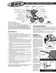
<strong>BOB</strong> QR<br />
Hook<br />
FIG.1<br />
Fork<br />
Pivot Bolt<br />
Pin Bungee<br />
Hook<br />
Pivot<br />
Tube<br />
All items same as YAK<br />
except those noted<br />
Trailer Anatomy (YAK & IBEX).<br />
Before proceeding with the trailer assembly <strong>and</strong> installation, you should confirm your<br />
bike <strong>and</strong> trailer are compatible with one another. Reference the Trailer/Bike Compatibility<br />
chart at the end of this manual.<br />
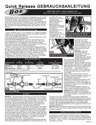
<strong>BOB</strong> Quick Release or <strong>BOB</strong> Nutz ...what do you need?<br />
Most modern bicycles use a quick release mechanism (QR) to secure wheels to the bicycle.<br />
The YAK & IBEX trailers are attached to the bicycle with a specially designed <strong>BOB</strong> QR. The<br />
<strong>BOB</strong> QR replaces the bikes original rear QR, <strong>and</strong> has a trailer attachment point on both ends.<br />
We make our QRs in three lengths (st<strong>and</strong>ard, 145mm (t<strong>and</strong>em), <strong>and</strong> Santana/160mm). If<br />
your bike does not use a QR to hold on the rear wheel, you will need a pair of <strong>BOB</strong> Nutz. <strong>BOB</strong><br />
Nutz <strong>and</strong> Quick Release specifications are listed at<br />
end of manual.<br />
NOTE: <strong>BOB</strong> TRAILERS INC. IS NOT RESPONSIBLE<br />
FOR INJURY, DAMAGE, OR FAILURE THAT<br />
RESULTS FROM FAULTY ASSEMBLY OR<br />
MAINTENANCE AFTER RECEIPT OF PRODUCT.<br />
For some older bikes with<br />
dropout spacing below 135mm:<br />
Metal cutting saw<br />
Metric die or nut; 5mm x .8mm<br />
Metal file<br />
Pivot Plate<br />
Skid<br />
Upper Rail<br />
Cargo<br />
Platform<br />
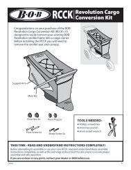
Tools Needed:<br />
Two 4mm hex wrenches (allen wrenches)<br />
Two 10mm wrenches (or adjustable wrenches)<br />
8 mm wrench (YAK only)<br />
Phillips screwdriver (YAK only)<br />
Slotted screwdriver<br />
Lower<br />
Rail<br />
Shock Tower<br />
Pivot Bolt<br />
ASSEMBLY INSTRUCTIONS<br />
• Trailer Wheel QR<br />
• Flag with Flag Pole<br />
• Spare Attachment Pin<br />
• Bungee Cord<br />
• Owner's Manual<br />
• Dry Sak (YAK Plus & IBEX Plus only)<br />
Rail Tie<br />
Cargo<br />
Stop<br />
Upper Shock<br />
Axle<br />
FIG.2<br />
Flag<br />
Fender<br />
Fender Wheel<br />
Bracket Dropout<br />
Fender<br />
Reflector<br />
Wheel<br />
Reflector<br />
Tire<br />
Rim<br />
Wheel Quick<br />
Release<br />
Trailer in extreme counter-clockwise<br />
rotation showing contact between<br />
derailleur pivot housing <strong>and</strong> trailer fork.<br />
AVOID this condition. If you believe this<br />
has occurred, inspect your derailleur, QR,<br />
<strong>and</strong> pins for damage.<br />
1. UNPACK: Remove trailer, small<br />
parts box <strong>and</strong> box contents, Dry<br />
SAK, etc. Plastic packaging<br />
material was used to protect the<br />
rear dropouts <strong>and</strong> the wheel axles.<br />
Remove these plastic pieces as<br />
well as all other packaging material.<br />
2. FORK ASSEMBLY: For shipping<br />
purposes, the trailer fork has been<br />
6mm bolt<br />
Locknut &<br />
Washer<br />
attached to the frame pointing to the rear of the trailer, Fig. 3. The fork<br />
will need to be removed <strong>and</strong> rotated 180 degrees, <strong>and</strong> then reattached<br />
prior to use, as shown in Fig 4.<br />
A) Remove the lock nut (Fig. 3, using two 10mm wrenches) <strong>and</strong> flat washer<br />
then fully remove the long 6mm bolt. This will free the fork from the<br />
trailer frame. Remove the fork. To reinstall the fork pointing forward,<br />
align the holes in the pivot plates of the trailer frame <strong>and</strong> the pivot<br />
tube in the fork as shown in Fig. 4.<br />
Pivot Tube<br />
B) Insert the long 6mm bolt with a washer on each end then<br />
tighten the lock nut, Fig. 4. Tighten the lock nut to 60 inch<br />
pounds (70 cm-kgs).<br />
Washer<br />
3. SWING ARM INSTALLATION (IBEX ONLY):<br />
A) Begin by first removing the pivot bolt <strong>and</strong> washers,<br />
Fig. 1, using two 10mm wrenches.<br />
B) Next install the swingarm pivot in the shock tower.<br />
The pivot is wider than the shock tower opening <strong>and</strong><br />
will need to be twisted so the left bushing/side of the swingarm goes through the opening first<br />
<strong>and</strong> exits the left side window as shown in Fig. 5.<br />
C) To get the right side bushing inside the tower, align it with the upper right h<strong>and</strong> corner of<br />
the tower opening as shown in Fig. 6 <strong>and</strong> rotate forward. The pivot should now be inside the<br />
shock tower. You will install the pivot bolt after installing the upper shock bolt.<br />
D) Remove the upper shock axle, Fig. 1. Align the shock axle with the holes in the shock tower<br />
<strong>and</strong> install the axle <strong>and</strong> washer, Fig. 7, <strong>and</strong> tighten to 60 inch-pounds (70 cm-kgs) using two<br />
5mm Allen wrenches.<br />
E) The pivot axle will need to be aligned with the pivot bolt holes in the shock tower. These<br />
are located above <strong>and</strong> forward of the windows in the sides of the tower. The fit between the<br />
pivot axle <strong>and</strong> tower is a tight tolerance fit so it will take some effort to move the pivot into<br />
position. This can be done by pushing on the back of the swingarm <strong>and</strong> rotating the pivot axle<br />
into alignment with the pivot bolt holes as<br />
shown in Fig. 8. Once aligned, install pivot bolt<br />
<strong>and</strong> washers, Fig. 8, <strong>and</strong> tighten to 60 inchpounds<br />
(70 cm-kgs) using two 10mm wrenches.<br />
4. FENDER ASSEMBLY (YAK ONLY):<br />
A) Fender Reflector Installation - The fender<br />
reflector attaches to the rear portion of the<br />
fender. The reflector has a threaded stud built<br />
into it. Attach the reflector to the fender by<br />
inserting the stud into the upper hole <strong>and</strong> the<br />
plastic "alignment pin" into the lower hole of<br />
the fender as shown in Fig. 9. Next, place the<br />
washer over the portion of the stud extending<br />
through the underside of the fender. Thread<br />
the nut on <strong>and</strong> tighten with an 8mm wrench.<br />
B) Fender Bracket Attachment - First, attach<br />
the fender bracket to the fender. Place the<br />
fender bracket in the center of the two holes<br />
in the fender <strong>and</strong> align the mounting hardware<br />
with them as shown in Fig. 10. Insert the screws<br />
through the holes from the outside of the fender.<br />
Place the threaded backing plate on the inside<br />
of the fender <strong>and</strong> tighten the screws using a<br />
screwdriver.<br />
C) Fender Attachment - The fender attaches<br />
to the trailer in three places. Begin by removing<br />
the screw <strong>and</strong> washers from the forward fender<br />
mount on the trailer frame. Attach the fender<br />
to the trailer by inserting the bolt <strong>and</strong> washer<br />
through the slot in the fender. Next place the<br />
second washer behind it (s<strong>and</strong>wiching the<br />
fender with washers) as shown in Fig. 11.<br />
Tighten the bolt securely with a 4mm Allen<br />
wrench. Next, attach the fender brackets to<br />
the left <strong>and</strong> right dropouts. Insert the bolt<br />
through the washer <strong>and</strong> then through the loop<br />
in the fender bracket as shown in Fig. 12. Align<br />
the bolt with the eyelet in the dropout <strong>and</strong><br />
tighten securely with a 4mm Allen wrench.<br />
FIG.3 Fork Rotated To Rear.<br />
FIG.5<br />
Left Bushing through shock<br />
tower opening <strong>and</strong> left window.<br />
FIG.6<br />
Locknut<br />
Pivot<br />
Plate<br />
6mm<br />
Bolt<br />
FIG.4 Rotated Fork & Bolt Assembly.<br />
Left<br />
Bushing<br />
Through<br />
Window<br />
Right<br />
Bushing<br />
Right Bushing aligned with upper<br />
right shock tower opening.
YAK/IBEX OWNER’S MANUAL<br />
(800) 893-2447 www.bobgear.com<br />
13501 South Ridge Drive Charlotte, North Carolina 28273<br />
2<br />
OMT01C<br />
5. WHEEL REFLECTORS: The trailer comes<br />
with two spoke reflectors which mount onto the<br />
spokes of the trailer wheel.<br />
A) Reflectors should be mounted 90 degrees<br />
from the valve stem, Fig. 13. The reflectors<br />
should be installed by weaving them through<br />
the spokes. The reflectors attach to the spoke<br />
with the white slotted attachment "screw", Fig.<br />
14. Remove attaching screw from reflector.<br />
Place reflector in position between wheel<br />
spokes <strong>and</strong> centered on a spoke approximately<br />
90 degrees from valve stem.<br />
B) Install screw, Fig. 14, over spoke <strong>and</strong> into<br />
receiving hole of reflector. Using a screwdriver,<br />
turn screw 90 degrees clockwise to lock reflector<br />
in position. Repeat the above steps for the<br />
second reflector to be installed opposite the<br />
position of the first reflector. This reflector<br />
configuration will keep the trailer wheel balanced<br />
<strong>and</strong> vibration free.<br />
6. YAK & IBEX WHEEL INSTALLATION<br />
USING QR (FIG. 15): NOTE: Follow all<br />
instructions exactly. If you are unsure how to<br />
operate the quick release, please consult your<br />
bicycle dealer or contact <strong>BOB</strong>. Fig. 15 shows<br />
the anatomy of the quick release.<br />
A) Remove adjust nut <strong>and</strong> one spring from the<br />
quick release.<br />
B) Insert the quick release rod through the hole<br />
in the axle.<br />
C) Install the second spring with the small end<br />
pointing towards the hub then install adjust nut.<br />
D) Slide wheel into the dropouts, FIG. 16, <strong>and</strong><br />
confirm wheel is centered between the wheel<br />
stays.<br />
IMPORTANT: The quick release is NOT a nut<br />
<strong>and</strong> bolt system. It is a cam-activated tightening<br />
mechanism. Tighten the QR as follows:<br />
E) Move the QR lever perpendicular (at a 90<br />
degree angle) to the trailer, FIG. 16.<br />
F) Turn the adjusting nut until it comes in<br />
contact with the trailer dropout.<br />
G) Move the quick release lever to the closed<br />
position, FIG. 17. The word CLOSE should be<br />
clearly visible on the lever <strong>and</strong> it should be<br />
parallel to the wheel stay.<br />
H) NOTE: It should require considerable<br />
pressure to close the lever when it is properly<br />
adjusted. If you do not feel this resistance,<br />
turn the quick release lever back to the adjusting<br />
position, FIG. 16, <strong>and</strong> tighten the adjust nut<br />
by h<strong>and</strong> (it is not necessary to use tools) one<br />
or two more turns in the clockwise direction<br />
then move the quick release lever to the closed<br />
position, FIG. 17. When properly adjusted, it<br />
requires 80-105 inch - pounds of torque to<br />
move the lever to the fully closed position.<br />
7. SAFETY FLAG: IMPORTANT: The flag<br />
is extremely important in making you <strong>and</strong> your<br />
FIG.10<br />
Attach the fender bracket to the<br />
fender with mounting hardware<br />
as shown.<br />
FIG.7<br />
Axle Washer<br />
Upper Axle Bolt Installation.<br />
Pivot<br />
Bolt<br />
FIG.8<br />
FIG.9<br />
Allen<br />
Screw<br />
Correct orientation of the reflector<br />
on the rear fender.<br />
FIG.11<br />
Washers<br />
Nut<br />
Pivot Axle Aligned With holes in<br />
Tower.<br />
Attachment of fender to trailer<br />
frame.<br />
trailer visible to others. Always make sure the flag is<br />
correctly installed when using your trailer.<br />
A) Press the two metal ends (silver) of the flag sections<br />
together making sure they insert into one another<br />
completely.<br />
B) Install completely into the flag tube. On the YAK<br />
the flag tube is located on the left side of the cargo<br />
stop, FIG. 18. On the IBEX it is located in the middle<br />
of the shock tower, FIG. 19.<br />
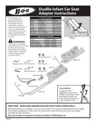
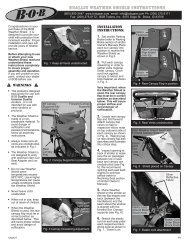
8. <strong>BOB</strong> QUICK RELEASE (QR) INSTALLATION:<br />
IMPORTANT: Bicycle manufacturers use a large<br />
Attachment of fender bracket to dropout<br />
eyelet.<br />
variety of components <strong>and</strong> materials to build their<br />
bikes <strong>and</strong> the thickness of the rear wheel dropouts<br />
vary greatly. It is extremely important to have your<br />
<strong>BOB</strong> QR sized to the appropriate length <strong>and</strong> correctly<br />
installed on your bike. Please note the dropout inside<br />
dimension assumes that the dropouts are firmly<br />
pressed against the hub axle over locknuts, alleviating<br />
any gap between the two <strong>and</strong> allowing for an accurate<br />
measurement. The QR's primary role is to secure the<br />
rear wheel to your bike, <strong>and</strong> secondarily, it is the<br />
structural link between the bike <strong>and</strong> trailer. For a QR<br />
to work properly, the QR rod must extend past the<br />
dropout on the derailleur side by a minimum of 3/8 FIG.13<br />
inch (10mm) <strong>and</strong> maximum of 3/4 inch (19mm). Fig.<br />
20 shows the anatomy of the <strong>BOB</strong> Quick Release. Wheel reflector correctly positioned.<br />
A) Remove the bike's rear QR. Remove the adjust<br />
nut <strong>and</strong> one conical spring from the <strong>BOB</strong> QR <strong>and</strong><br />
install into the rear wheel axle hole on the non-derailleur<br />
side.<br />
B) With the QR cam lever in the closed position (note<br />
that "CLOSE" is visible on the cam lever) push the<br />
quick release through the bike's rear axle until it<br />
contacts the bike frame dropout face.<br />
C) Check for a minimum of 3/8 inch (10mm) <strong>and</strong><br />
FIG.14<br />
maximum 3/4 inch (19mm) of threaded rod extending<br />
past the dropout face, Fig. 21. IMPORTANT: If the Wheel reflector "screw".<br />
amount of rod extending past the dropout face is less<br />
than 10mm, you will<br />
need a longer quick<br />
release. Please consult<br />
Adjusting Nut Rod Quick Release Lever<br />
the <strong>BOB</strong> Quick Release<br />
Model table at the end<br />
of this manual to find the<br />
correct QR for your bike.<br />
If the amount of rod is<br />
greater than 19mm, see<br />
the next section: FIG.15<br />
"TRIMMING THE <strong>BOB</strong> St<strong>and</strong>ard QR Anatomy.<br />
QR ROD". If you do not<br />
underst<strong>and</strong> this section,<br />
contact your local bike dealer or call <strong>BOB</strong> for help.<br />
D) Install the 2nd conical spring onto the QR rod<br />
(small hole first) <strong>and</strong> then the adjust nut.<br />
E) With the QR lever perpendicular (at a 90 degree<br />
angle) to the frame, Fig. 22, tighten the adjusting nut<br />
clockwise until it is snug against the dropout face.<br />
F) Move the QR lever until "CLOSE" is visible on the<br />
lever, Fig. 23, <strong>and</strong> it is parallel to the frame.<br />
IMPORTANT: for highest strength, it should require<br />
considerable pressure to close the QR lever when it<br />
is properly adjusted <strong>and</strong> tightened.<br />
G) If you do not feel this resistance turn the quick<br />
release lever back to the adjusting position, Fig. 22.<br />
Tighten the QR adjust nut by h<strong>and</strong> (it is not necessary<br />
to use tools) one or two more turns in the clockwise<br />
direction. Proper adjustment requires 80 to 105 inch<br />
- pounds of torque to move the lever to the fully<br />
"CLOSED" position.<br />
9. TRIMMING THE <strong>BOB</strong> QR ROD: If your QR rod<br />
measurement (see above section, step "C") exceeds<br />
3/4 inch (19mm), proceed with the following:<br />
A) If your measurement is 25 mm (for example),<br />
subtract 19 mm (max. length) to determine length of<br />
rod to be cut. (25 - 19 = 6mm.) As a general rule, it<br />
is recommended to maximize the length of the rod.<br />
B) Thread a 5mm x .8mm nut or threading die onto<br />
the QR rod past the area to be cut. (after trimming<br />
the QR rod, the nut / die will clean up the threads<br />
Conical<br />
Springs<br />
FIG.12<br />
FIG.16<br />
QR lever perpendicular to drop out face.<br />
FIG.17<br />
QR lever closed.<br />
Cam Housing<br />
when it is removed).<br />
C) Clamp the QR rod in a vise, being careful not to<br />
damage the threads,Fig. 24.<br />
D) Measure from the tip of the QR rod <strong>and</strong> cut the<br />
rod with a metal cutting saw.<br />
E) Using a file, shape the end of the rod into a conical<br />
shape.<br />
F) Remove the nut (or die) <strong>and</strong> verify the QR rod has<br />
been cut to the proper length by repeating steps B<br />
<strong>and</strong> C in the previous section then complete QR<br />
installation by following steps D through G in previous<br />
section.<br />
10. TRAILER ATTACHMENT: Now that the <strong>BOB</strong><br />
quick release is correctly installed, attach the trailer<br />
to the quick release. To do this correctly, follow the<br />
steps below:<br />
A) The stainless steel pivoting <strong>BOB</strong>BINS on the quick<br />
release skewer are asymmetrical as shown in Fig.<br />
20. This asymmetrical design allows the <strong>BOB</strong>BINS<br />
to be reversed, allowing for a variance of approximately<br />
13mm in outside dimensional span of the bike's<br />
dropouts.<br />
B) With the bike stabilized <strong>and</strong> the trailer unloaded,<br />
check the fit between the fork hooks <strong>and</strong> the slots<br />
of the <strong>BOB</strong>BINS. It is easiest to do this with the bike<br />
in the upright-position <strong>and</strong> trailer straight behind the<br />
bike. St<strong>and</strong> on the left side of the bike facing towards<br />
the trailer. Allow the bike seat to rest against your<br />
FIG.18<br />
YAK flag tube.<br />
FIG.19<br />
IBEX flag tube.<br />
hip. Bend at the hips <strong>and</strong> lift trailer with both h<strong>and</strong>s, Fig. 25, <strong>and</strong> place the fork hooks on the<br />
quick release <strong>BOB</strong>BINS. If the hooks do not fit into the <strong>BOB</strong>BIN slots by slightly exp<strong>and</strong>ing<br />
or compressing the fork, it will be necessary to reverse the <strong>BOB</strong>BINS. Fig. 26 shows a situation<br />
where the hooks do not fit easily <strong>and</strong> the <strong>BOB</strong>BINS need to be reversed.<br />
C) With the quick release installed, <strong>and</strong> using a 4mm Allen wrench, remove the <strong>BOB</strong>BIN<br />
retaining screws, Fig. 20, on both the left <strong>and</strong> right sides. Remove the <strong>BOB</strong>BINS <strong>and</strong> reverse<br />
them noting the position of the lock <strong>and</strong> flat washers.<br />
D) With the <strong>BOB</strong>BINS reversed, reinstall the retaining screws <strong>and</strong> lock washers. Tighten the<br />
Lock Flat<br />
Washer Washer<br />
Retaining<br />
Screw<br />
FIG.20<br />
Bobbin<br />
<strong>BOB</strong> QR Anatomy.<br />
Lever<br />
Conical<br />
Springs<br />
retaining screws securely.<br />
E) Attach the trailer by aligning the slots of the <strong>BOB</strong>BINS with the slots in the fork hooks. Fig.<br />
27 shows the fork hooks correctly installed on the <strong>BOB</strong>BINS.<br />
F) With the trailer hooks placed on the bobbins, insert the pin in the hole in the front edge of<br />
the hook. Slide the pin under the bobbin <strong>and</strong> into the hole in the back edge of the hook.<br />
Rotate the pin up, toward the button head post on the hook. To secure the pin, it is necessary<br />
to press it downward <strong>and</strong> toward the hook. When properly installed, the pin fits between the<br />
hook <strong>and</strong> the head on the button head post, as shown in Fig. 28. The rubber lanyard retains<br />
the pin when not installed.<br />
IMPORTANT: The pins are CRITICAL to keeping the trailer attached to the <strong>BOB</strong> Quick<br />
Release. Inspect pins for proper installation every time you ride. Incorrectly installed pins<br />
can allow the trailer to detach from the bicycle <strong>and</strong> cause a severe accident. Please see your<br />
dealer or call <strong>BOB</strong> if you do not underst<strong>and</strong><br />
the pin installation procedure.<br />
11. SHOCK STIFFNESS ADJUSTMENT<br />
(IBEX ONLY): The IBEX trailer has three<br />
shock stiffness settings depending on the<br />
weight of the load you are carrying. It is<br />
important to correctly adjust the shock each<br />
time you change the load in the trailer to keep<br />
from bottoming out the suspension system.<br />
Repeated bottoming out of the suspension<br />
system will shorten the life of the trailer frame, FIG.21<br />
swing arm, <strong>and</strong> shock assembly. To adjust<br />
the suspension stiffness proceed as follows: Measuring threaded QR rod extending past drop<br />
A) Unweight the trailer wheel by lifting the out face. The QR must be in the closed position.<br />
Rod<br />
Adjusting Nut<br />
Flat Lock<br />
Washer Washer<br />
Bobbin<br />
Retaining<br />
Screw
YAK/IBEX OWNER’S MANUAL<br />
(800) 893-2447 www.bobgear.com<br />
13501 South Ridge Drive Charlotte, North Carolina 28273<br />
3<br />
OMT01C<br />
trailer by the frame. This should be done with<br />
the trailer empty.<br />
B) Fully depress the shock adjustment button<br />
on the right side, Fig. 29.<br />
C) While holding down the button, slide the<br />
shock to the desired setting.<br />
D) Release the button <strong>and</strong> pull swing arm<br />
back <strong>and</strong> forth until the button snaps into<br />
place.<br />
Position 1 (forward most position) is the<br />
softest setting <strong>and</strong> Position 3 (rearward<br />
most position) is the stiffest. As a general<br />
rule use the following guidelines when setting<br />
up the suspension system:<br />
Position 1: 0 - 25 lbs (0 -11 kg) of cargo.<br />
Position 2: 25 - 45 lbs (11 - 20 kg) of cargo.<br />
Position 3: 45 - 70 lbs (20 -32 kg) of cargo.<br />
12. DRY SAK: Loading tips: Make sure all<br />
sharp objects are covered to prevent<br />
punctures of the DRY SAK wall. Place heaviest<br />
objects in the bottom for maximum stability.<br />
Closing procedure to insure DRY SAK is<br />
watertight:<br />
A) Load Bag, Fig.30<br />
B) Bring the 2 black plastic strips together<br />
at the rim of the SAK.<br />
C) Roll strips together as you would a paper<br />
bag <strong>and</strong> synch tight with the end buckles.<br />
D) Connect center buckle over the 2 h<strong>and</strong>les<br />
<strong>and</strong> synch tight.<br />
Securing in trailer:<br />
E) Place black section of SAK towards rear.<br />
Hook spider bungee to frame tubes <strong>and</strong> / or<br />
bungee hooks to retain DRY SAK cargo.<br />
PARKING TIPS<br />
• If possible park your bike <strong>and</strong> trailer on level<br />
ground.<br />
• Rest trailer on a curb against the parking<br />
skid (FIG. 1) lean it against a building, fence,<br />
or sign<br />
• PARK MODE: Fig. 31 shows the bike <strong>and</strong><br />
trailer in “Park Mode”. Turn the bike 90<br />
degrees to the trailer with h<strong>and</strong>lebars turned<br />
90 degrees to the bike. Lower trailer frame<br />
to the ground, contacting the parking skid<br />
(FIG. 1) <strong>and</strong> the trailer will st<strong>and</strong> up on its<br />
own. NOTE: This feature works best when<br />
the trailer is loaded <strong>and</strong> does not work on all<br />
bikes.<br />
• To "un-park" your bike, place one h<strong>and</strong> on<br />
the h<strong>and</strong>lebars, <strong>and</strong> one h<strong>and</strong> on the seat<br />
while walking forward <strong>and</strong> pulling the seat<br />
towards you as the trailer will stabilize in the<br />
horizontal position.<br />
• A st<strong>and</strong>ard kick st<strong>and</strong> for your bicycle works<br />
well in most circumstances to keep the bike<br />
<strong>and</strong> trailer upright.<br />
FIG.26<br />
Bobbin spacing does not align with hook spacing.<br />
Bobbins must be reversed for proper alignment.<br />
FIG.22<br />
QR lever perpendicular to drop out face.<br />
FIG.23<br />
QR lever closed.<br />
FIG.24<br />
QR with die in place <strong>and</strong> clamped for cutting.<br />
FIG.25<br />
Correct position for bike <strong>and</strong> trailer attachment.<br />
FIG.27<br />
Fork hooks correctly aligned <strong>and</strong> installed<br />
on bobbins.<br />
Pin<br />
FIG.28<br />
Pin Correctly Installed.<br />
FIG.30<br />
Button Head Post<br />
Bobbin Lanyard<br />
Dry SAK closing sequence.<br />
Hook<br />
CAUTION: A small percentage of bike's rear derailleurs are positioned such that when parked,<br />
the fork of the YAK contacts the derailleur pivot housing. Fig. 2 Verify with a friend that there<br />
is adequate clearance before leaning the bike <strong>and</strong> trailer completely over in park mode. Note:<br />
reversing the installation of the QR (install<br />
from the drive side / right side of bike) helps<br />
eliminate this problem. <strong>BOB</strong> TRAILERS<br />
assumes no responsibility for bent derailleurs<br />
that result from the owner neglecting to check<br />
for proper clearance prior to utilizing "PARK<br />
MODE".<br />
LIMITED WARRANTY<br />
<strong>BOB</strong> <strong>Trailers</strong> Inc. takes pride in its<br />
workmanship <strong>and</strong> strives to manufacture the<br />
best products possible. Therefore, we<br />
warranty our YAK <strong>and</strong> IBEX trailers against<br />
defects in material <strong>and</strong> workmanship subject<br />
to the conditions listed below. Since no<br />
product is indestructible, it does not cover<br />
defects attributable to or resulting from normal<br />
wear, abuse or alteration.<br />
<strong>BOB</strong> <strong>Trailers</strong>, Inc. warrants original parts of<br />
FIG.31<br />
FIG.29<br />
Position 3<br />
Shock adjustment button.<br />
Shock adjustment<br />
button in Position 1<br />
Trailer & h<strong>and</strong>lebars<br />
are 90 degrees<br />
to the bike.<br />
Parking position. Note: correct direction to turn the<br />
h<strong>and</strong>lebars is towards the trailer.<br />
<strong>BOB</strong> <strong>Trailers</strong> products to be free from defects in materials <strong>and</strong> workmanship subject to the<br />
following conditions <strong>and</strong> limitations:<br />
• Frame is warranted for five years.<br />
• Components are warranted for one year.<br />
• Warranty is only valid for the original purchaser.<br />
• Proof of purchase is required to exercise this warranty.<br />
• Labor <strong>and</strong> transportation are not included.<br />
• Normal wear, neglect, abuse, accidents, improper assembly or maintenance, or the installation<br />
of parts or accessories not compatible with the original intended use of the trailer, as sold,<br />
are not covered by this warranty.<br />
• Warranty claims must be made through an authorized dealer.<br />
• This warranty is limited to the replacement of the defective part. <strong>BOB</strong> <strong>Trailers</strong> shall in no<br />
event be responsible for consequential or special damages.<br />
• This limited warranty is the only express or implied warranty applicable to <strong>BOB</strong> <strong>Trailers</strong>. Any<br />
implied warranties, including warranties of merchantability <strong>and</strong> fitness shall be limited in scope<br />
<strong>and</strong> duration in accordance with this limited warranty.<br />
MAINTENANCE SCHEDULE<br />
Part Service Period**<br />
B.O.B QR Check tightness Every ride<br />
Check for wear & damage Monthly<br />
QR <strong>BOB</strong>BINS Check retaining screw tightness Every ride<br />
Remove <strong>and</strong> clean bushing Monthly<br />
Replace As needed<br />
Hub Bearings Check for smooth rotation Monthly<br />
replace* As needed<br />
Retaining Pins Inspect Every ride<br />
Tire Check Pressure Weekly<br />
Inspect for damage Monthly<br />
Fork Check pivot screw tightness Weekly<br />
Fork Bushings Check for looseness* Yearly<br />
Wheel True* As needed<br />
Wheel QR Check tightness Every ride<br />
IBEX only<br />
Swingarm pivot Check retaining bolt tightness Weekly<br />
Upper Shock bolt Check bolt tightness Weekly<br />
*We recommend this service be performed by a trained bicycle mechanic at a professional<br />
bicycle dealership. This requires special tools <strong>and</strong> skill.<br />
**May require more frequent service if you ride in wet, s<strong>and</strong>y, or dusty conditions. All<br />
the above frequencies are intended as guidelines. Depending on where you ride <strong>and</strong><br />
your riding style, these services may need to be performed more frequently.<br />
Trailer Model<br />
IBEX / IBEX PLUS<br />
YAK / YAK PLUS<br />
TRAILER/BIKE COMPATIBILITY<br />
Bicycle<br />
Dropout<br />
A - Dropout<br />
Spacing<br />
Compatibility<br />
Included<br />
<strong>BOB</strong> Quick<br />
Release<br />
Included<br />
<strong>BOB</strong> Fork<br />
B - Fork<br />
Clearance<br />
Wheel<br />
Diameter<br />
Range<br />
126.5 - 140mm St<strong>and</strong>ard QR St<strong>and</strong>ard 360mm* 20" - 27"<br />
YAK 28 / YAK 28 PLUS<br />
126.5 - 140mm St<strong>and</strong>ard QR 28 420mm** 20" - 28"<br />
IBEX 28 / IBEX 28 PLUS<br />
YAK PLUS SANTANA 160mm Santana QR Santana 360mm* 20" - 27"<br />
Please note there are some bikes that have 145mm dropout spacing. We make a 145mm<br />
QR for use with these bikes. The 145mm QR is compatible with the IBEX, IBEX Plus,<br />
YAK, YAK Plus, YAK 28 <strong>and</strong> YAK 28 Plus.<br />
* Fits 20", 26" & 700C wheels without fenders<br />
** intended for bikes with 28" wheels or bikes with 700c/27" wheels <strong>and</strong> full wrap fenders <strong>and</strong> reflectors
YAK/IBEX OWNER’S MANUAL<br />
(800) 893-2447 www.bobgear.com<br />
13501 South Ridge Drive Charlotte, North Carolina 28273<br />
<strong>BOB</strong> NUTZ MODELS<br />
<strong>BOB</strong> Nutz are special adapters for bicycles with solid axles, replacing the original nuts <strong>and</strong><br />
giving an attachment point at either extremity of the axle. We make four <strong>BOB</strong> Nutz models<br />
to fit different axle configurations (See chart below).<br />
<strong>BOB</strong> Nutz Model Axle Diameter Thread Pitch Common Applications<br />
3/8 x 24 3/8 inch 24 tpi Single speed coaster brake hubs<br />
3/8 x 26 3/8 inch 26 tpi Shimano Nexus 4 <strong>and</strong> 7 speeds,<br />
Shimano 3 speed coaster brakes,<br />
<strong>English</strong> <strong>and</strong> Japanese solid axles<br />
10 x 1 10mm 1mm ISO <strong>and</strong> Japanese solid axles<br />
IGH (Internal 10.5mm 1mm Sachs multi-speed hubs with<br />
Gear Hubs) indicator chain shifting Sturmey<br />
13/32 inch 26 tpi Archer multi-speed hubs with<br />
indicator chain shifting<br />
<strong>BOB</strong> QUICK RELEASE MODELS<br />
The <strong>BOB</strong> Quick Release comes in three different models to fit<br />
a wide range of rear hub spacings:<br />
A<br />
B<br />
Bicycle<br />
Dropout<br />
C<br />
D<br />
A B C D<br />
QR Model Rod Threaded Dropout Inside Allowable Dropout<br />
Length Length Dimension Outside Dimension<br />
<strong>BOB</strong> QR 165mm* 32mm 126.5 - 140mm** 140 - 156mm<br />
<strong>BOB</strong> 145 QR 175mm* 35mm 145mm** 145 - 164mm<br />
<strong>BOB</strong> Santana QR 190mm* 30mm 160mm** 165 - 180mm<br />
*Measurement is with QR lever in closed position<br />
**Dropout inside dimension (C) to measure the same as bicycle hub’s axle over locknut dimension.<br />
4<br />
OMT01C