ZF Servocom - Paul Nutzfahrzeuge
ZF Servocom - Paul Nutzfahrzeuge
ZF Servocom - Paul Nutzfahrzeuge

Create successful ePaper yourself
Turn your PDF publications into a flip-book with our unique Google optimized e-Paper software.
S e r v i c e<br />
8352 W 5/00 e<br />
Function<br />
Maintenance<br />
Inspection<br />
Troubleshooting<br />
<strong>ZF</strong> <strong>Servocom</strong> ® RAS<br />
(Rear Axle Steering)<br />
<strong>ZF</strong> Lenksysteme GmbH<br />
D-73522 Schwaebisch Gmuend<br />
Telephone (07171) 31-0 Fax (07171) 31-4396
Contents / System description / Notes<br />
Contents:<br />
1 Functional description ................................................................ 2<br />
2 Safety instructions ................................................................... 5<br />
3 Maintenance ........................................................................ 5<br />
4 Inspection .......................................................................... 6<br />
5 Disassembly of the <strong>ZF</strong>-<strong>Servocom</strong> RAS ................................................... 7<br />
6 Installation of the <strong>ZF</strong>-<strong>Servocom</strong> RAS .................................................... 8<br />
7 Charging with gas ................................................................... 9<br />
8 Filling with oil ...................................................................... 10<br />
9 Bleeding ........................................................................... 10<br />
10 Settings and tightening torques ....................................................... 11<br />
11 Special tools ....................................................................... 12<br />
12 Troubleshooting ..................................................................... 13<br />
System description:<br />
! The <strong>ZF</strong>-<strong>Servocom</strong> RAS is a rear axle steering system which hydrostatically transmits the steering<br />
movement of the front axle to the rear axle (as in the case of a hydraulic braking system).<br />
! The hydrostatic power is transmitted from the master cylinder (front axle) via hydraulic connections<br />
to the centering cylinder (rear axle).<br />
Notes:<br />
! This manual is exclusively intended to supplement the existing instructions for operation, maintenance<br />
and inspection of the <strong>ZF</strong>-<strong>Servocom</strong> steering systems.<br />
! All the work described here should be carried out within the framework of routine maintenance and<br />
inspection of the <strong>ZF</strong>-<strong>Servocom</strong>.<br />
! All the settings and test values or dimensions listed are standard values which apply for all versions.<br />
Exception: The individual vehicle manufacturers may prescribe different values. Please take note<br />
of the service information circulars and the spare parts list!<br />
<strong>ZF</strong>-<strong>Servocom</strong> RAS<br />
Page<br />
1
Function<br />
1 Functional description<br />
1.1 Mechanical design<br />
1.2 Function<br />
2<br />
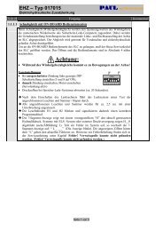
1 <strong>ZF</strong>-<strong>Servocom</strong> 3 Centering cylinder<br />
2 Master cylinder with 4 Hydraulic accumulator<br />
pressure limiting valve 5 Hydraulic lines<br />
and replenishing vavle 6 Pressure switch<br />
7 Connecting rod<br />
! The steering movement is transmitted from the <strong>ZF</strong>-<strong>Servocom</strong> or front axle steering (1) mechanically<br />
via a connecting rod (7) and hydraulically via hydraulic lines (5) to the master cylinder (2) which is<br />
mounted on the front axle or vehicle chassis.<br />
⎨ The master cylinder (2) hydrostatically transmits the steering movement via hydraulic lines (5) to the<br />
centering cylinder (3) on the trailing axle. This axle is steered by the centering cylinder via the piston<br />
rod.<br />
⎨ The hydraulic accumulator (4) improves the rigidity of the hydrostatic transmission system and acts<br />
permanently on the two centering pistons which are integrated into the centering cylinder (3).<br />
⎨ Pressure limiting valves are installed in the master cylinder (2) in order to protect the hydrostatic<br />
system against impermissibly high pressures which could damage the system.<br />
⎨ The master cylinder (2) also includes replenishing valves to prevent the formation of a vacuum in<br />
the unpressurized cylinder area and thus facilitate the steering movement.<br />
The pressure switch (6) monitors the system pressure and is connected to a pilot lamp.<br />
Additional information for versions with cut-off valve (8):<br />
The cut-off valve (8) (see figure on page 18) connects the lines L1 and L2 in case of breakdown of the<br />
hydraulic assistance of the front axle steering gear.<br />
This produces the fact that the <strong>ZF</strong>-<strong>Servocom</strong> RAS does not co-steer and that no additional actuating<br />
forces are required at the front axle steering gear.<br />
<strong>ZF</strong>-<strong>Servocom</strong> RAS
Function<br />
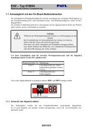
1.3 Function when travelling straight ahead<br />
Operating pressure - front axle steering<br />
System pressure<br />
Accumulator pressure (gas-charged)<br />
! The master cylinder (2) is designed so that the cylinder areas Z1 and Z2 are connected when travelling<br />
straight ahead and when the steering angle is less than 5 o . This ensures that the four cylinder<br />
areas Z3, Z4, Z5 and Z6 in the centering cylinder (3) are pressurized by the hydraulic accumulator<br />
(4), thus holding the trailing axle in position for travel straight ahead.<br />
⎨ Short-circuiting cylinder areas Z1 and Z2 and centering the trailing axle additionally ensures that the<br />
master cylinder and centering cylinder (3) are synchronized. This compensates any hydrostatic offsets<br />
which may occur, for example as a result of minute leaks.<br />
<strong>ZF</strong>-<strong>Servocom</strong> RAS<br />
3
Function<br />
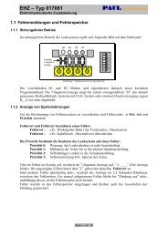
1.4 Function when steering to the right<br />
⎩<br />
⎨<br />
Operating pressure - front axle steering / return flow<br />
Operating pressure - front axle steering<br />
System pressure / return flow<br />
System pressure<br />
Accumulator pressure (gas-charged)<br />
! Cylinder space Z7 in the master cylinder (2) is pressurized by the <strong>ZF</strong>-<strong>Servocom</strong> or front axle steering<br />
(1) and displaces the piston rod to the right.<br />
⎨ This pressurizes the hydraulic fluid in cylinder space Z1, as well as in cylinder space Z6 via hydraulic<br />
lines (5) if the steering angle is greater than 5 o .<br />
⎨ The piston rod of the centering cylinder (3) is consequently displaced to the left and the trailing axle<br />
is steered to the left.<br />
4<br />
<strong>ZF</strong>-<strong>Servocom</strong> RAS<br />
⎩
Safety instructions / Maintenance<br />
2 Safety instructions<br />
Attention:<br />
! Lines and connections, etc. must not be opened until the system pressure of the <strong>ZF</strong>-<strong>Servocom</strong> RAS<br />
has been relieved.<br />
⎨ The bleeder valves must be opened slowly to bleed the system.<br />
⎨ Note that at least the system pressure is still present in the hydrostatic system even when the engine<br />
has been switched off.<br />
! The front axle steering must not be actuated when connections or lines, etc. on the rear axle<br />
steering system have been opened, since the high resultant pressures may cause injuries.<br />
3 Maintenance<br />
3.1 Maintenance intervals<br />
⎨ The maintenance intervals which apply for the <strong>ZF</strong>-<strong>Servocom</strong> steering system or which are specified<br />
by the vehicle manufacturer also apply for the <strong>ZF</strong>-<strong>Servocom</strong> RAS.<br />
Note any other or additional intervals specified by the vehicle manufacturer.<br />
3.2 Maintenance work<br />
⎨ Check oil level<br />
<strong>ZF</strong>-<strong>Servocom</strong> RAS:<br />
The oil level cannot be checked. This is also unnecessary, since oil cannot be lost during normal<br />
operation and when the <strong>ZF</strong>-<strong>Servocom</strong> RAS is in good condition.<br />
<strong>ZF</strong>-<strong>Servocom</strong> (front axle steering):<br />
Check oil level in oil tank.<br />
If the oil level exceeds the maximum permitted, this may be due to a leak in the master cylinder.<br />
⎨ Check for external leaks<br />
Hydraulic lines, connections, master cylinder, centering cylinder and hydraulic accumulator must<br />
be visually inspected for leaks.<br />
There must not be any visible leakage. Only the piston rods of the master and centering cylinders<br />
may be coated with a film of oil. The formation of drops is not permissible.<br />
⎨ Check bellows<br />
Check that the bellows is seated correctly and undamaged.<br />
The bellows must not be twisted.<br />
<strong>ZF</strong>-<strong>Servocom</strong> RAS<br />
5
Inspection<br />
4 Inspection<br />
4.1 Inspection intervals<br />
! The same inspection intervals apply for the <strong>ZF</strong>-<strong>Servocom</strong> RAS as for the <strong>ZF</strong>-<strong>Servocom</strong> steering.<br />
⎨ Note any other or additional intervals specified by the vehicle manufacturer.<br />
4.2 Inspection work<br />
4.2.1 Carry out the maintenance work described in section 3.2.<br />
6<br />
Bleeder valve<br />
Connection<br />
4.2.2 Check system pressure on hydraulic accumulator<br />
⎨ Remove cap on hydraulic accumulator.<br />
<strong>ZF</strong>-<strong>Servocom</strong> RAS<br />
Tool [1]<br />
Valve B<br />
Spindle A<br />
⎨ Slightly loosen the hexagon socket head screw of connection A2 (back off approx. one-quarter<br />
turn anticlockwise).<br />
⎨ Screw tool [1] onto connection A2 by hand with the union nut.<br />
⎨ Turn pressure gauge so that it can be read off conveniently.<br />
⎨ Close valve B.<br />
⎨ Turn spindle A of tool [1] to the left until the pointer on the pressure gauge begins to move. Then<br />
give it one more full turn.
Inspection<br />
! Read off the system pressure. Required: 15 +1/-3 bar (see note on page 1).<br />
Note:<br />
If the system pressure corresponds with the required value, the accumulator pressure need not be<br />
checked as described in section 4.2.3 since it will invariably be correct in such cases.<br />
⎨ Tighten the hexagon socket head screw with spindle A in order to close the valve.<br />
⎨ Unscrew the union nut and remove tool [1].<br />
⎨ Tighten the hexagon socket head screw with a torque of 25 Nm and leak-test the valve with<br />
sealing spray or soapy water.<br />
⎨ Refit the cap.<br />
4.2.3 Check hydraulic accumulator pressure<br />
⎨ Connect tool [2] to connection A1.<br />
Tool [2]<br />
⎨ Turn the valve anticlockwise with tool [2] to relieve the system pressure. At the same time, check<br />
whether the pilot indicator installed in the cab switches at a remaining pressure of 2...5 bar.<br />
⎨ Connect tool [1] to connection A2 as described in section 4.2.2.<br />
⎨ Read off the accumulator pressure. Required: 10 +1/-3 bar (see note on page 1).<br />
<strong>ZF</strong>-<strong>Servocom</strong> RAS<br />
Valve<br />
Note:<br />
If the accumulator pressure does not correspond to the required value, the accumulator pressure<br />
must be increased as described in section 7 or the hydraulic accumulator replaced.<br />
⎨ Close the valve of tool [2] by turning clockwise.<br />
⎨ Check whether the oil tank of tool [2] has been filled (oil grade see section 6.1).<br />
⎨ Build up the system pressure with tool [2] by actuating the hand pump. Required: 15 +1/-3 bar<br />
(see note on page 1).<br />
⎨ Remove tool [1] as described in section 4.2.2.<br />
⎨ Close the valve of the hydraulic accumulator as described in section 4.2.2.<br />
⎨ Remove tool [2].<br />
4.2.4 Check cut-off valve (8) and switch relay (9)<br />
⎨ Connect cable plug of the signal sensor (10) to earth.<br />
⎨ Steer the steering wheel so that the steering output shaft angle is bigger than 5 o .<br />
⎨ The <strong>ZF</strong>-<strong>Servocom</strong> RAS must not co-steer.<br />
⎨ If the <strong>ZF</strong>-<strong>Servocom</strong> RAS co-steers, the failure must be removed - see troubleshooting.<br />
7
Disassembly / Installation<br />
5 Disassembly of the <strong>ZF</strong>-<strong>Servocom</strong> RAS<br />
8<br />
Attention:<br />
Note the safety instructions in section 2.<br />
5.1 Master and centering cylinders<br />
⎨ Mark connections and installed position of cylinders.<br />
⎨ Disconnect master and centering cylinders and drain oil.<br />
5.2 Hydraulic accumulator<br />
⎨ Unscrew union piece from hydraulic accumulator.<br />
⎨ Release catches and remove hydraulic accumulator.<br />
6 Installation of the <strong>ZF</strong>-<strong>Servocom</strong> RAS<br />
6.1 Master and centering cylinders<br />
6.1.1 Preparing cylinders for installation<br />
⎨ Move piston rod to middle position.<br />
Tool [3]<br />
Master cylinder<br />
<strong>ZF</strong>-<strong>Servocom</strong> RAS<br />
Tool [4]<br />
Centering cylinder<br />
⎨ Mount tool on piston rod so that bevel on left-hand side (see arrow on tool) positively engages<br />
the bevel at the end of the piston rod. Move piston rod until the right-hand side of the tool (tool<br />
[3]) or the shoulder (tool [4] - see marking on tool) contacts the face end of the cylinder.<br />
⎨ Fill master and centering cylinders with oil.<br />
Oil grade:<br />
Only oil grades approved by the vehicle manufacturer (e.g. Pentosin CHF 11S) may be used in the<br />
<strong>ZF</strong>-<strong>Servocom</strong> RAS (without <strong>ZF</strong>-<strong>Servocom</strong> steering). The oil must not be mixed with other grades.<br />
Attention:<br />
In the case of the master cylinder, only ports L1, L2 and L3 in the centre of the cylinder (see diagram<br />
on page 6) may be filled with the above oil grade.<br />
The external ports L4 and L5 must be filled with the oil grade used in the <strong>ZF</strong>-<strong>Servocom</strong> or front<br />
axle steering.<br />
6.1.2 Installation instructions<br />
⎨ Screw ball joint onto piston rod.<br />
Attention:<br />
Note values X and Y for the minimum screw depth.
Installation / Charging with gas<br />
Value X<br />
Piston rod<br />
<strong>ZF</strong>-<strong>Servocom</strong> RAS<br />
Value Y<br />
Cylinder pipe<br />
⎨ Value X (piston rod): Master cylinder: max. 13 mm (for 8346 974 163:max. 31.5 mm)<br />
Centering cylinder: max. 31.5 mm<br />
Value Y (cylinder pipe): Master cylinder: max. 14 mm<br />
Centering cylinder: max. 19 mm<br />
⎨ Oil the mating faces and screw thread of the ball joint.<br />
⎨ Turn the steered wheels into the exact straight-ahead position.<br />
⎨ Install the master and centering cylinders so that the line connections point upwards.<br />
⎨ Screw the ball joint mounted on the cylinder pipe onto the frame (master cylinder) and axle (centering<br />
cylinder) and lock it in place.<br />
Tightening torque: Clamp: 45...50 Nm<br />
Castellated nut: 250...280 Nm (for 8346 974 163: 210...230 Nm)<br />
⎨ Move piston rod to middle position as described in section 6.1.<br />
⎨ Oil the screw thread and mating face.<br />
⎨ After connection to the piston rod, fit the ball joint into the wheel steering lever by twisting and<br />
turning.<br />
Attention:<br />
Note values X and Y.<br />
Tighten (torque see above) and secure the clamp and castellated nut.<br />
Check sealing edges, sealing faces and sealing rings of the connections for signs of damage.<br />
Connect the piping so that it is oil-tight.<br />
⎨ Following the installation of the centering and the master cylinder, the chassis geometry must be<br />
measured and readjusted, if necessary.<br />
6.2 Hydraulic accumulator<br />
⎨ Insert hydraulic accumulator in union piece and secure it.<br />
⎨ Tighten union piece (Ermeto GE) with a torque of 80+10 Nm.<br />
7 Charging with gas<br />
⎨ Connect tool [1] to connection A2 as described in section 4.2.2.<br />
Attention:<br />
Only nitrogen may be used as the charging gas. Explosion hazard!<br />
Only nitrogen cylinders with pressure reducing valve and relief valve may be used.<br />
⎨ Connect charging hose to tool [1] and nitrogen cylinder.<br />
9
Charging with gas / Filling with oil / Bleeding<br />
! Set pressure reducing valve to 10+1 bar (see note on page 1).<br />
! Slowly open the shutoff valve on the nitrogen cylinder.<br />
! Open valve B of tool [1].<br />
10<br />
<strong>ZF</strong>-<strong>Servocom</strong> RAS<br />
Tool [1]<br />
Valve B<br />
! When the accumulator pressure reaches 10+1 bar (see note on page 1),<br />
close the shutoff valve on the cylinder and valve B on tool [1].<br />
Spindle A<br />
! Check the accumulator pressure again after waiting 5 minutes, during which time the temperature<br />
is equalized.<br />
! Remove tool [1] as described in section 4.2.2.<br />
! Close the valve of the hydraulic accumulator as described in section 4.2.2.<br />
8 Filling with oil<br />
! Oil grade:<br />
Only oil grades approved by the vehicle manufacturer (e.g. Pentosin CHF 11S) may be used in the<br />
<strong>ZF</strong>-<strong>Servocom</strong> RAS (without <strong>ZF</strong>-<strong>Servocom</strong> steering). The oil must not be mixed with other grades.<br />
! Amount of oil:<br />
Approx. 6 litres are required to fill the complete <strong>ZF</strong>-<strong>Servocom</strong> RAS (without <strong>ZF</strong>-<strong>Servocom</strong> steering<br />
or front axle steering).<br />
! Move master cylinder to middle position (see section 6.1).<br />
! Connect tool [2] to connection A1. Fill the oil tank of tool [2] with oil (oil grade as above) in order<br />
to avoid pumping air.<br />
! In order to facilitate the filling and subsequent bleeding process, it is advisable to open some of the<br />
bleeder valves of lines L3, L1 and L2 (see diagram on page 6) and to close them again when oil<br />
emerges.<br />
! Increase the system pressure to 15+1 bar (see note on page 1) by actuating the hand pump.<br />
9 Bleeding<br />
9.1 <strong>ZF</strong> - <strong>Servocom</strong> RAS<br />
! Connect tool [2] to connection A1. Fill the oil tank of tool [2] with oil (oil grade as above) in order<br />
to avoid pumping air.<br />
! Actuate the hand pump of tool [2] to build up pressure and ensure that the system is pressurized<br />
during the entire bleeding process.
Bleeding / Settings and tightening torques<br />
! Open the highest bleeder valve in line L3 until air bubbles no longer escape; then reclose it so that<br />
it is oil-tight.<br />
! Open the other bleeder valves in line L3 and then reclose them so that they are oil-tight.<br />
! Bleed lines L1 and L2 as described above.<br />
! Bleed the cylinder ports and then reclose them so that they are oil-tight.<br />
! Check the system pressure. Required: 15+1 bar (see note on page 1)<br />
9.2 <strong>ZF</strong>-<strong>Servocom</strong> or front axle steering and corresponding circuit of master cylinder<br />
! Start the engine.<br />
! Open the bleeder valves or ports of lines L4 and L5 until air bubbles no longer escape; then reclose<br />
them so that they are oil-tight.<br />
! Turn the steering from one limit position to the other several times.<br />
! This allows any remaining air in the oil to escape via the oil tank.<br />
! The oil level in the oil tank may rise by 1...2 cm when the engine is switched off and the system<br />
has been fully bled.<br />
9.3 Bleed the <strong>ZF</strong>-<strong>Servocom</strong> RAS again as described in section 9.1<br />
! Check the system pressure. Required: 15�1 bar (see note on page 1)<br />
! Remove tool [2].<br />
10 Settings and tightening torques<br />
- Settings:<br />
Accumulator pressure: Check: 10+1/-3 bar (see note on page 1)<br />
Charging: 10�1 bar (see note on page 1)<br />
System pressure: Check: 15+1/-3 bar (see note on page 1)<br />
Charging: 15�1 bar (see note on page 1)<br />
Value X: Master cylinder: max. 13 mm (for 8346 974 163max. 31.5 mm)<br />
Centering cylinder: max. 31.5 mm<br />
Value Y: Master cylinder: max. 14 mm<br />
Centering cylinder: max. 19 mm<br />
- Tightening torques:<br />
Hydraulic accumulator: Hexagon socket head screw 25 Nm<br />
Union piece (Ermeto GE) 80+10 Nm<br />
Master and centering cylinders: Clamp 45...50 Nm<br />
Castellated nut 250...280 Nm<br />
(for 8346 974 163: 210...230 Nm)<br />
<strong>ZF</strong>-<strong>Servocom</strong> RAS<br />
11
Special tools<br />
11 Special tools<br />
Note:<br />
The special tools listed below refer to the standard version and the design version on the basis of which<br />
the entire manual has been compiled. Other tools may consequently be required for the particular unit<br />
in question.<br />
Tool [1]<br />
12<br />
<strong>ZF</strong>-<strong>Servocom</strong> RAS<br />
Part. No.<br />
Test device 7016 798 516<br />
Tool [2]<br />
Hydraulic unit for 7418 798 563<br />
filling with oil<br />
Tool [3]<br />
Gauge for 8346 798 301<br />
master cylinder<br />
(For 8346 974 163:<br />
8346 798 303)<br />
Tool [4]<br />
Gauge for 8346 798 302<br />
centering cylinder
13<br />
12 Troubleshooting<br />
This troubleshooting procedure presupposes that there The applicated letters and numbers (e.g. 2, L5) refer to the illustration are<br />
no defects in the front axle steering! on page 17.<br />
Attention: Note the safety instructions in section 2.<br />
Fault Cause Check Remedy<br />
Pressure switch ! Loss of oil; ! Check steering system ! Eliminate cause of leak.<br />
indicator lights up when external leak in system for external leaks (visual examination) Fill system with oil 15�1 bar (see note<br />
vehicle power supply is and system pressure - required: on page 1) and bleed it.<br />
switched on 15+1-3 bar (see note on page 1) See operating instructions.<br />
! Internal leak in ! Check oil level in oil ! Seal or replace cylinder<br />
master cylinder (2) tank (is too high)<br />
! Hydraulic accumulator (4) ! Check maximum pressure ! Charge hydraulic accumulator<br />
defective in hydraulic accumulator - required: with nitrogen or replace it.<br />
10 +1/-3 bar (see note on page 1) 10�1 bar (see note on page 1)<br />
- see operating instructions<br />
! Internal leak in ! Open screw plug A3 ! Seal or replace centering cylinder<br />
centering cylinder (3) - oil must not emerge<br />
oil leaking from L3 to A3<br />
Pressure switch indicator lights ! Press switch (6) defective ! Check correct functioning of ! Replace pressure switch<br />
up when vehicle power supply pressure switch as directed by vehicle<br />
is switched on although manufacturer<br />
RAS is functioning correctly<br />
Indicator does not light ! Contactofpressure ! Check correct functioning of pressure ! Replace pressure switch<br />
up although RAS is not switch (6) is sticking switch as directed by vehicle<br />
functioning correctly manufacturer<br />
! Indicator defective ! Check correct functioning of indicator ! Replace indicator<br />
! Electric lead defective ! Check wiring for continuity with the aid ! Replace wiring or repair break<br />
of a multi-purpose measuring instrument in connection<br />
Oil tank indicator ! Internal leak in master cylinder ! Check system pressure ! Seal or replace cylinder<br />
lights up while steering (2) - oil leaking leaking (is too high) - required:<br />
from L5 to L2 or from L4 to L1 15+1-3 bar (see note on page 1)
14<br />
Fault Cause Check Remedy<br />
Synchronization error. ! Mechanical connecting elements ! Visual examination of ! Replace defective parts<br />
Rear axle does not centre between axle (ball joints, mechanical connecting elements<br />
back to the precise piston rod, steering knuckle,<br />
straight-ahead position etc.) and cylinder are stiff,<br />
- only when stationary bent, with backlash<br />
-alsowhendriving<br />
- in one direction<br />
- in both directions<br />
! Air in RAS steering system ! Bleed steering system and ! Fill system with oil 15�1 bar<br />
check system pressure - required: (see note on page 1) and bleed it<br />
15 +1 -3 bar (see note on page 1) (see operating instructions)<br />
! Geometry of rear ! Check rear axle for ! Set axle values as directed<br />
axle not OK specified axle values by vehicle manufacturer<br />
! System pressure ! Check steering system for external ! Repair leak<br />
too low, external leak leaks (visual examination) and check Fill with oil 15�1 bar (see note on<br />
existing system pressure - required: page1) and bleed system<br />
15 +1 -3 bar (see note on page 1) (see operating instructions)<br />
! Gas pressure of ! Check accumulator pressure ! Charge hydraulic accumulator with<br />
accumulator (4) too low - required: 10+1-3 bar (see note on nitrogen 10+1 bar (see note on page 1)<br />
page 1) or replace it (see operating instructions)<br />
! Internal leak in centering ! Remove screw plug (A3) - oil must not ! Seal or replace cylinder<br />
cylinder (3) - oil leaking emerge from the open cylinder port.<br />
from L3 to A3<br />
Middle position of master ! Set wheels to straight-ahead position. ! Set cylinders to middle position with<br />
and/or centering cylinder Check middle position of piston rod wheels in straight-ahead position.<br />
offset in relation to in master and centering cylinders See operating instructions<br />
straight-ahead position for setting<br />
of wheels
15<br />
Fault Cause Check Remedy<br />
Synchronization error ! Air in RAS steering system ! Check steering system for ! Eliminate cause of infiltrated air.<br />
Rear axle remains in external leaks Fill system with oil 15�1 bar (see note on<br />
straight-ahead position page 1) - see operating instructions<br />
and does not turn<br />
- only when stationary ! Too little oil in the RAS system. ! Check steering system for Eliminate cause of leak.<br />
- also when driving External leak in piping or in external leaks (visual examination) Fill system with oil 15�1 bar (see note on<br />
- in one direction master and/or centering cylinder and existing system pressure - required: page 1) and bleed it<br />
- in both directions 15+1-3 bar (see note on page 1)<br />
! Leak in control system of ! Check oil leakage at cylinder ports ! Seal or replace cylinder<br />
master cylinder (2) - oil leaking L1 to L3 or L2 to L3, as appropriate.<br />
from L1 or L2 to L3 Turn front axle in the corresponding<br />
directiontobechecked.<br />
Unscrew and seal line<br />
L1 to L3 or L2 and L3.<br />
Set system pressure of RAS in line<br />
L2 or L1 to 20 bar on Minimess port.<br />
Measure leakage oil at open cylinder<br />
ports for approx. 1 minute.<br />
No more than 0.02 dm 3 /min<br />
oil may emerge from both ports taken<br />
together.<br />
! Leak in main cylinder part of ! Set wheels to straight-ahead ! Seal or replace cylinder<br />
centering cylinder (3) - oil position and check oil leakage<br />
leaking from L1 to L2 or vice at cylinder ports<br />
versa L1 or L2, as appropriate.<br />
Unscrew line L1 or L2<br />
from cylinder and seal it.<br />
Set system pressure to 20 bar via<br />
connection A1.<br />
Oil must not emerge from the open<br />
cylinder port.
16<br />
Fault Cause Check Remedy<br />
! Leak from main cylinder part ! Set wheels to straight-ahead position ! Seal or replace cylinder<br />
of centering cylinder (3) to and check oil leakage at cylinder port<br />
centering cylinder part L3.<br />
- oil leaking from L1 to L3 Unscrew and seal line L3.<br />
Set system pressure of RAS to 20 bar<br />
via connection A1.<br />
Oil must not emerge from<br />
the open cylinder port.<br />
! Lines no longer allow oil to pass ! Check piping and hoses for signs ! Replace damaged piping<br />
through of damage.<br />
Measure system pressure at<br />
the corresponding end of the piping.<br />
Additional information for versions with cut-off valve (8)<br />
<strong>ZF</strong>-<strong>Servocom</strong> RAS ! Defective cut-off valve (8) ! Start the engine. Interrupt connection ! If <strong>ZF</strong>-<strong>Servocom</strong> RAS does not<br />
No function between main power supply and<br />
cut-off valve<br />
function replace cut-off valve (8).<br />
! Defective switch relay (9) ! Switch on ignition (engine off)<br />
Take off main power supply plug from<br />
cut-off valve (8). Measure voltage.<br />
! Replace switch relay (9).<br />
Nominal value: main power supply ! No main power supply voltage<br />
voltage. Start engine. Measure voltage.<br />
Nominal value: 0V<br />
=> replace switch relay (9)<br />
! Defective signal sensor<br />
(e.g.flow rate indicator)<br />
! Check switching function. ! Replace signal sensor<br />
Legend to diagrams on page 17/18:<br />
1 front axle steering 6 pressure switch L1/L2 hydrostatic connecting line to master- and centering cylinder<br />
2 masterzylinder 7 connecting rod L3 pressure line<br />
3 centering cylinder 8 cut-off valve L4/L5 connecting line from front axle steering to mastercylinder<br />
4 hydraulic accumulator 9 switch relay A1 connection tube (oil side)<br />
5 hydraulic lines 10 signal sensor A2 connection tube at hydraulic accumulator (gas side)<br />
(e.g. flow rate indicator) A3 closing screw (centering cylinder)<br />
(E) bleeder valve<br />
A, B, C, D, E, X, Y, T, W, V connection identification sticked up at the aggregates
17<br />
Version without cut-off-valve (8)
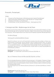
Company instruction PAUL NUT<strong>ZF</strong>AHRZEUGE<br />
BLEEDING GUIDE FOR <strong>ZF</strong>-SERVOCOM<br />
1. Lift vehicle frame on front side.<br />
2. Move steering straight ahead.<br />
3. Stop engine during bleeding.<br />
4. Connect hydraulic pump to non return valve beneath centering cylinder<br />
(see photo).<br />
5. Increase system pressure to 15 bar with hydraulic pump.<br />
6. Attention: Use only Pentosin CH11S (DC-No.: A00 198 03 10), complete<br />
filling appr. 6 ltr.<br />
7. Loose slightly cap nut of pressure switch (close to master cylinder),<br />
hydraulic line L3 and release air. Close cap nut.<br />
8. Bleeding MINIMESS-connectors by turns (hydraulic line L1 and L2).<br />
9. Increase in between system pressure to appr. 15 bar. Minimum pressure<br />
during bleeding > 10 bar.<br />
10. Star engine an steer slowly 5 times left to right to left.<br />
11. Stop engine and steer straight ahead.<br />
12. For oil calming down wait appr. 10 minutes.<br />
13. Repeat bleeding procedure for hydraulic line L1 and L2.<br />
14. Increase hydraulic system pressure to 15 bar.<br />
15. Final performance control.