Dapol Railbus Assembly - Hollywood Foundry
Dapol Railbus Assembly - Hollywood Foundry
Dapol Railbus Assembly - Hollywood Foundry

You also want an ePaper? Increase the reach of your titles
YUMPU automatically turns print PDFs into web optimized ePapers that Google loves.
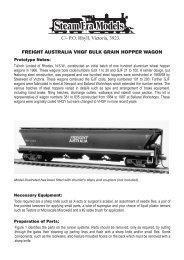
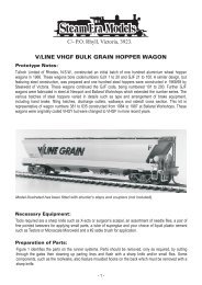
Assembling the <strong>Dapol</strong> <strong>Railbus</strong> C47 Kit<br />
<strong>Assembly</strong> Instructions<br />
It will be necessary to assemble the model in a different sequence to<br />
that in the <strong>Dapol</strong> assembly instructions. The railbus body will be<br />
completed before the powered underframe, in the reverse of the <strong>Dapol</strong><br />
instructions.<br />
Please follow these model assembly instructions and not the <strong>Dapol</strong><br />
ones. Lines from the <strong>Dapol</strong> instructions will be inserted into this<br />
document where applicable.<br />
Please test fit all parts before cementing in place. There are many<br />
mould marks that prevent parts from fitting together correctly, and<br />
these need to be shaved off.<br />
DCC Considerations<br />
If you are planning to control the model by DCC, it is best to make<br />
alterations to the wiring of the mechanism before beginning assembly.<br />
There are four wires from the pickups connected to the motor as<br />
supplied. They are soldered to a small printed circuit board on the rear<br />
of the motor. Un-solder the wires from this board, a light touch is all<br />
that is necessary, do not dwell on the board for too long. You will find<br />
that the wires are twisted together in pairs, one pair on each side.<br />
These wires are colour coded according to the NMRA standard<br />
scheme, and can be connected to the same coloured wires of your<br />
decoder, red and black. The orange wire from the decoder should be<br />
connected to the motor printed circuit pad on the same side as the red<br />
pick-up wires, and the grey wire goes to the motor on the black side.<br />
Assembling the Model<br />
Begin by laying the floor section of the kit (42) down with the smooth,<br />
or cabin side, uppermost. Mark the position of 4 holes to mount the<br />
mechanism to the floor. The holes are in line with the existing four<br />
holes that locate the underframe (2), but are spaced slightly further<br />
apart. For the two existing holes that are 6.5mm apart, the new holes<br />
should be 17mm apart, or 8.5mm either side of centre. The other two<br />
holes should be marked in line with the two existing holes at 15mm<br />
spacing, the new holes being 23mm apart, or 11.5mm either side of<br />
centre. Once the holes are marked, carefully drill them out to 2mm<br />
diameter, preferably by hand.<br />
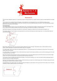
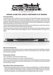
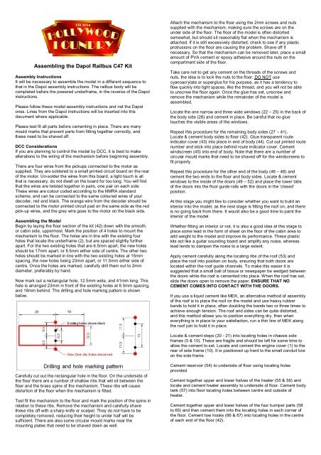
Now mark out a rectangular hole, 12.5mm wide, and 41mm long. This<br />
hole is arranged 23mm in front of the existing holes at 6.5mm spacing,<br />
and 18mm behind. The drilling and hole marking pattern is shown<br />
below.<br />
Attach the mechanism to the floor using the 2mm screws and nuts<br />
supplied with the mechanism, making sure the screws are on the<br />
under side of the floor. The floor of the model is often distorted<br />
somewhat, but should sit reasonably flat when the mechanism is<br />
attached. If it is still excessively distorted, check to see if any plastic<br />
protrusions on the floor are causing the problem. Shave off if<br />
necessary. So that the mechanism can be removed later, place a small<br />
amount of PVA cement or epoxy adhesive around the nuts on the<br />
compartment side of the floor.<br />
Take care not to get any cement on the threads of the screws and<br />
nuts, the idea is to lock the nuts to the floor. DO NOT use<br />
cyanoacrylate or superglue for his purpose, as it has a tendency to<br />
flow quickly into tight spaces, like the thread, and you will not be able<br />
to unscrew the floor again. Once the glue has set, unscrew and<br />
remove the mechanism while the remainder of the model is<br />
assembled.<br />
Locate the one narrow and three wide windows (22 – 25) in the back of<br />
the body side (26) and cement in place. Be careful that no glue<br />
touches the visible areas of the windows.<br />
Repeat this procedure for the remaining body sides (27 – 41).<br />
Locate & cement body sides to floor (42). Glue transparent route<br />
indicator cover (43) into place in end of body (44). Cut out printed route<br />
number and stick into place behind route indicator cover. Cement<br />
windscreen (45) into end of body. Note that there are a number of<br />
circular mould marks that need to be shaved off for the windscreens to<br />
fit properly.<br />
Repeat this procedure for the other end of the body (46 – 48) and<br />
cement the two ends to the floor and body sides. Locate & cement<br />
windows to the inside of the doors (49 – 52) and place the lower tabs<br />
of the doors into the floor guide rails with the doors in the ‘closed’<br />
position.<br />
At this stage you might like to consider whether you want to build an<br />
interior into the model, as the next stage is fitting the roof on, and there<br />
is no going back from there. It would also be a good time to paint the<br />
interior of the model.<br />
Whether fitting an interior or not, it is also a good idea at this stage to<br />
place some lead in the form of sheet on the floor of the cabin area to<br />
add weight to the model and improve its performance. These plastic<br />
kits act like a guitar sounding board and amplify any noise, whereas<br />
lead tends to dampen the noise to a large extent.<br />
Apply cement carefully along the locating ribs of the roof (53) and<br />
place the roof into position on body, ensuring that both doors are<br />
located within the roof guide channels. To make this easier it is<br />
suggested that a small ball of tissue or newspaper be wedged between<br />
the doors while the roof is cemented into place. When the roof has set,<br />
slide the doors open to remove the paper. ENSURE THAT NO<br />
CEMENT COMES INTO CONTACT WITH THE DOORS.<br />
If you use a liquid cement like MEK, an alternative method of assembly<br />
of the roof is to place the roof on the model and use heavy rubber<br />
bands to hold it in place, often doubling the bands two or three times to<br />
achieve enough tension. The roof and sides can be quite distorted,<br />
and this method allows you to position everything dry, then when<br />
everything is in place to your satisfaction, run a thin line of MEK along<br />
the roof join to hold it in place.<br />
Locate & cement steps (20 - 21) into locating holes in chassis side<br />
frames (5 & 10). These are fragile and should be left for some time to<br />
allow the cement to set. Locate and cement the engine cover (1) to the<br />
rear of side frame (10). It is positioned up hard to the small conduit box<br />
on the side frame.<br />
Carefully cut out the rectangular hole in the floor. On the underside of<br />
the floor there are a number of shallow ribs that will sit between the<br />
floor and the brass spine of the mechanism. These ribs will cause<br />
distortion of the floor when the mechanism is fitted.<br />
Test fit the mechanism to the floor and mark the position of the spine in<br />
relation to these ribs. Remove the mechanism and carefully shave<br />
these ribs off with a sharp knife or scalpel. They do not have to be<br />
completely removed, reducing their height to under half will be<br />
sufficient. There are also some circular mould marks near the<br />
mounting plates that need to be shaved down as well.<br />
Cement reservoir (54) to underside of floor using locating holes<br />
provided.<br />
Cement together upper and lower halves of the heater (55 & 56) and<br />
locate and cement heater assembly to underside of floor. Cement body<br />
tank (57) into floor locating holes between centre and outside of<br />
heater.<br />
Cement together upper and lower halves of the four bumper parts (58<br />
to 65) and then cement them into the locating holes in each corner of<br />
the floor. Cement tow hooks (66 & 67) into locating holes in the centre<br />
of each end of the floor (42).
Due to the presence of the mechanism, the entire underframe section<br />
(2) cannot be used. For the same reason, the auxiliary reservoir and<br />
diverter valve (3 & 4) also cannot be used.<br />
Locate the headstock (14) and cut the locating tabs off the rear.<br />
Cement brake reservoir (15) into holes in headstock. Also fit<br />
suspension springs (16 & 17) into the square holes at the end of the<br />
headstock, and cement. Refer to the kit diagram for orientation.<br />
Locate opposite end headstock (11) and cut locating tabs off the rear.<br />
Cement fuel tanks (12 & 13) onto the raised locations on the<br />
headstock. The straps on the fuel tanks are vertical. Fit suspension<br />
springs (18 & 19) into the square holes at the end of the headstock,<br />
and cement.<br />
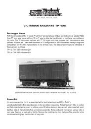
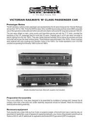
Position the headstock assemblies and cement them to the floor ribs<br />
by applying cement to the underside of the small triangular spring<br />
mounts. The position of each headstock is shown in the diagram<br />
below, with respect to the ribs on the floor of the car. This should result<br />
in the headstocks being as close to the mechanism as possible without<br />
fouling it.<br />
The position of the headstocks is slightly further apart from where they<br />
should be, and the side frames will not quite reach. To compensate,<br />
cut four sections of the piece of white polystyrene rectangular section,<br />
supplied with the mechanism, each piece 3.5mm long.<br />
Cement these sections to the inside of the headstocks as shown<br />
below:<br />
Test fit the side frames in between the packed out headstocks. If your<br />
positioning of the headstocks is correct, the side frames will not quite<br />
fit now. File back the inside of the notch in each end of the side frame<br />
until it fits snugly between the headstocks.<br />
Cement the side frames in position, checking that they are mounted<br />
perpendicular to the floor. Under the centre of the side frames, there is<br />
a wide flat rib section (near the doors). Run a bead of cement along<br />
the join between this rib and the top of the side frames to provide<br />
additional strength.<br />
There is some spare space under the model between the side frames<br />
and the spine of the mechanism. If possible, place further shaped lead<br />
weights in this region to improve performance.<br />
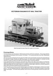
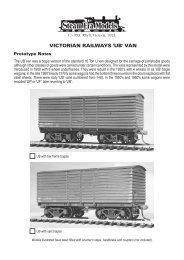
The model should now be painted and the decals applied. The<br />
mechanism may then be re-installed in the body.<br />
The following photos show the model in a completed, but not painted<br />
form, to show you how it should look: