Pumps Industrial Products - hydrofit group
Pumps Industrial Products - hydrofit group
Pumps Industrial Products - hydrofit group

You also want an ePaper? Increase the reach of your titles
YUMPU automatically turns print PDFs into web optimized ePapers that Google loves.
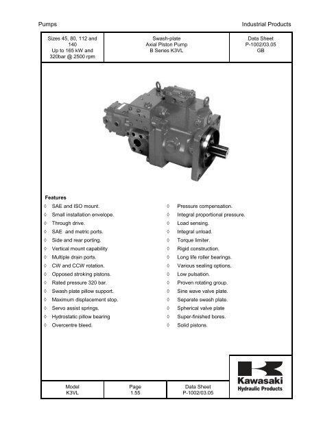
<strong>Pumps</strong><br />
Sizes 45, 80, 112 and<br />
140<br />
Up to 165 kW and<br />
320bar @ 2500 rpm<br />
Swash-plate<br />
Axial Piston Pump<br />
B Series K3VL<br />
<strong>Industrial</strong> <strong>Products</strong><br />
Data Sheet<br />
P-1002/03.05<br />
GB<br />
Features<br />
◊ SAE and ISO mount.<br />
◊ Small installation envelope.<br />
◊ Through drive.<br />
◊ SAE and metric ports.<br />
◊ Side and rear porting.<br />
◊ Vertical mount capability<br />
◊ Multiple drain ports.<br />
◊ CW and CCW rotation.<br />
◊ Opposed stroking pistons.<br />
◊ Rated pressure 320 bar.<br />
◊ Swash plate pillow support.<br />
◊ Maximum displacement stop.<br />
◊ Servo assist springs.<br />
◊ Hydrostatic pillow bearing<br />
◊ Overcentre bleed.<br />
◊<br />
◊<br />
◊<br />
◊<br />
◊<br />
◊<br />
◊<br />
◊<br />
◊<br />
◊<br />
◊<br />
◊<br />
◊<br />
◊<br />
◊<br />
Pressure compensation.<br />
Integral proportional pressure.<br />
Load sensing.<br />
Integral unload.<br />
Torque limiter.<br />
Rigid construction.<br />
Long life roller bearings.<br />
Various sealing options.<br />
Low pulsation.<br />
Proven rotating <strong>group</strong>.<br />
Sine wave valve plate.<br />
Separate swash plate.<br />
Spherical valve plate<br />
Super-finished bores.<br />
Solid pistons.<br />
Model<br />
K3VL<br />
Page<br />
1.55<br />
Data Sheet<br />
P-1002/03.05
<strong>Pumps</strong><br />
<strong>Industrial</strong> <strong>Products</strong><br />
General Description<br />
The K3VL Series Swash Plate Type Axial Piston <strong>Pumps</strong> are designed to specifically satisfy the mobile,<br />
marine and general industrial machinery market where a medium pressure variable displacement pump is<br />
required. K3VL <strong>Pumps</strong> are available in nominal displacements ranging from 45 to 140 cm3/rev with various<br />
pressure, torque limiter, and combination load sensing control options.<br />
Technical Description<br />
The components of the K3VL pump can be divided into three sub-<strong>group</strong>ings:<br />
Rotating Group - Providing the main rotary pumping action.<br />
Swash Plate Group - To vary the pump’s delivery flow rate.<br />
Valving Cover Group - Providing the switching of oil between suction and delivery ports.<br />
Model<br />
K3VL<br />
Page<br />
2.55<br />
Data Sheet<br />
P-1002/03.05
<strong>Pumps</strong><br />
<strong>Industrial</strong> <strong>Products</strong><br />
Technical Description (continued)<br />
The Rotating Group<br />
The Rotating Group comprises:<br />
(a) Drive shaft, 111<br />
(b) Cylinder block,141<br />
(c) Pistons, 9 x 151<br />
(d) Shoes, 9 x 152<br />
(e) Setting plate, 153<br />
(f) Spherical bush, 156<br />
(g) Cylinder springs.9 x 157<br />
The drive shaft is coupled to the cylinder block through a splined section and supported at both of its ends<br />
by bearings and the drive shaft. The shoe is swaged over the spherical end of the piston forming a<br />
spherical ball joint. Additionally the shoe has a hydrostatic pocket to balance the hydraulic thrust developed<br />
by the piston pressure allowing the shoe to lightly slide against the shoe plate.<br />
The sub<strong>group</strong> consisting of the pistons and shoes are pressed against the shoe plate by the cylinder<br />
springs acting through the setting plate and the spherical bush. The force developed by these cylinder<br />
springs also press the cylinder block against the valve plate. With the smallest K3VL45 unit a single<br />
centralised spring with individual push pins provide the shoe and cylinder block hold down force.<br />
Swash Plate Group<br />
The Swash Plate Group comprises:<br />
(a) Swash plate, 212<br />
(b) Shoe plate, 211<br />
(c) Swash plate support, 251<br />
(d) Tilting bush, 214<br />
(e) Tilting pin, 531<br />
(f) Servo piston, 532<br />
(g) Servo assist springs. 535 & 536<br />
The swash plate on the reverse side to the shoe location is a cylindrical form which is a “pillow” supported<br />
by the hydrostatic bearing provided by the swash plate support. The tilting bush is inserted into the swash<br />
plate and into this is installed the spherical portion of the tilting pin which is coupled to the servo piston.<br />
Any linear movement of the servo piston produced by the regulator pressure applied to either end is<br />
translated through the tilting pin into an angular movement of the swash plate which varies the tilting or<br />
swash angle of the pump. A screw adjuster and lock nut is available to adjust the maximum tilting angle<br />
condition. The servo assist springs are provided to ensure good on stroking response particularly at low<br />
operating pressures.<br />
Model<br />
K3VL<br />
Page<br />
3.55<br />
Data Sheet<br />
P-1002/03.05
<strong>Pumps</strong><br />
<strong>Industrial</strong> <strong>Products</strong><br />
Technical Description (continued)<br />
Valve Cover Group<br />
The Valve Cover Group comprises:<br />
(a) Valve cover, 312<br />
(b) Valve plate, 313<br />
(c) Valve plate, 885<br />
The valve plate with its two “kidney” shaped ports is installed onto the valve plate located by the valve plate<br />
pin. These two ports serve to supply and exhaust oil to and from the cylinder block. The oil passage<br />
switched by the valve plate is connected to the externally piped suction and outlet pressure ports through<br />
the valve cover. This valve plate is spherical in form for all but the smallest 45 unit.<br />
Pump Operation<br />
When the pump’s drive shaft is driven by a prime mover (Electric motor, Engine etc.), the cylinder block<br />
being spline coupled to the shaft will also rotate. If the swash plate has been tilted, the pistons arranged in<br />
the cylinder block due to the shoe being retained on the swash plate surface will both rotate with the<br />
cylinder block and reciprocate once per revolution. Paying attention to one such piston then it will move<br />
away from the valve plate for half a rotation (suction stroke) and move towards the valve plate for the<br />
second half of rotation (oil delivery stroke). The larger the tilt angle, the longer the piston stroke and the<br />
higher is the pump’s displacement. As the swash plate tilting angle approaches so the piston makes no<br />
stroke and thereby delivers no oil.<br />
Through Drive Option<br />
The pump is available with a through drive capability (see installation section) where a through drive shaft<br />
with splined end is incorporated capable of taking a similar torque to that of the pump itself and an SAE “A”<br />
mounting interface is provided.<br />
By suitable use of adaptors and splined couplings a wide variety of through drive mounting capabilities are<br />
available. The formation of these kits and their relevant part numbers will be found in the installation<br />
section.<br />
Cover Kit SAE "A" Kit SAE "B" Kit<br />
Model<br />
K3VL<br />
Page<br />
4.55<br />
Data Sheet<br />
P-1002/03.05
<strong>Pumps</strong><br />
<strong>Industrial</strong> <strong>Products</strong><br />
Technical Data<br />
For applications outside the following parameters, please consult Kawasaki Precision Machinery (UK) Ltd.<br />
Hydraulic Data<br />
Pressure Fluid<br />
Mineral oil, phosphate ester, fatty acid ester and water glycol.<br />
Phosphate ester is only suitable for use with FPM seals.<br />
Use a high quality, anti-wear, mineral based hydraulic fluid when the<br />
pressure exceeds 207 bar. In applications where fire resistant fluids<br />
are required consult Kawasaki Precision Machinery (UK) Ltd. The<br />
following chart illustrates the effects on pump life when non-standard<br />
fluids are used:<br />
Fluid selection<br />
kinematic viscosity (cSt)<br />
1000<br />
600<br />
400<br />
200<br />
100<br />
80<br />
60<br />
40<br />
20<br />
15<br />
VG 100<br />
VG 68<br />
VG 46<br />
VG 32<br />
VG 22<br />
allowable temperature range<br />
10<br />
o<br />
o o o o o<br />
-20 0 20 40 60 80 100<br />
fluid temperature ( C)<br />
o<br />
o<br />
Model<br />
K3VL<br />
Page<br />
5.55<br />
Data Sheet<br />
P-1002/03.05
<strong>Pumps</strong><br />
<strong>Industrial</strong> <strong>Products</strong><br />
Technical Data (continued)<br />
Filtration & Contamination Control<br />
Filtration<br />
The most important means to prevent premature damage to the pump and associated equipment and to<br />
extend its working life, is to ensure that hydraulic fluid contamination control of the system is working<br />
effectively.<br />
This begins by ensuring that at the time of installation that all piping, tanks etc. are rigorously cleaned in a<br />
sanitary way. Likewise, during start up thorough flushing should be done at minimal operating pressure so<br />
as to remove any residual contamination. Flushing should be provided using an off line filtration system<br />
and after flushing the filter elements should be replaced.<br />
A full flow return line filter of 10 micron nominal should be utilised and in addition a 150 micron mesh<br />
suction strainer is recommended. Typical filtration circuits are shown in the K3VL brochure.<br />
To prevent contaminant ingress from the external environment a 5 to 10 micron filter within the tanks<br />
breather is also recommended.<br />
Suggested Acceptable Contamination Level<br />
The relationship between contamination level and pump life is very difficult to predict as it depends on the<br />
type and nature of the contaminant present in the system. Sand or Silica in particular, due to its abrasive<br />
nature, does significantly reduce the expected life of a pump.<br />
Based on the precondition that there is no significant presence of Silica type substances then a minimum<br />
Cleanliness level of 18/15 to ISO/DIS 4406 (NAS Class 9) is recommended.<br />
Working Fluid Types<br />
Anti-Wear Type Hydraulic fluid<br />
It is generally recommended to use an anti-wear type hydraulic fluid as the mineral oil type when the<br />
operating pressure exceeds 210 bar.<br />
Fire-resistant Fluids<br />
Some kind of fire-resistant fluids require special materials for seals, paint and metal finishing. Please<br />
consult Kawasaki Precision Machinery (UK) Limited and provide details of the particular fluid specification<br />
and the working conditions so that any special requirements can be ascertained.<br />
In general, fire-resistant fluids have a low viscosity index and their viscosity also changes significantly with<br />
operating temperature and service life. For this reason, the circuit should be provided with an adequately<br />
sized cooler or forced cooling so that temperatures can be stabilised.<br />
Due to the inherent water content of some of these fluids the minimum allowable suction pressure will be<br />
higher than that of an equivalent mineral oil and so needs to be fully evaluated by Kawasaki Precision<br />
Machinery (UK) Limited. The following table provides an overview of the precautions and characteristics<br />
that can be expected with these types of fluids.<br />
Model<br />
K3VL<br />
Page<br />
6.55<br />
Data Sheet<br />
P-1002/03.05
<strong>Pumps</strong><br />
<strong>Industrial</strong> <strong>Products</strong><br />
Technical Data (continued)<br />
Fire-resistant Fluids (continued)<br />
fluid type :-<br />
parameter :-<br />
Maximum Pressure<br />
(bar)<br />
Recommended Temperature<br />
Range (deg C)<br />
mineral<br />
oil<br />
phosphate<br />
ester<br />
polyol<br />
ester<br />
water<br />
glycol<br />
320 320 320 210<br />
20 ~ 60 20 ~ 60 20 ~ 60 10 ~ 50<br />
Cavitation susceptability<br />
Expected life expectancy compared<br />
to mineral oil<br />
100% 60% ~ 100% 50% ~ 100% 20% ~ 80%<br />
recommended<br />
usable (higher density)<br />
Model<br />
K3VL<br />
Page<br />
7.55<br />
Data Sheet<br />
P-1002/03.05
<strong>Pumps</strong><br />
<strong>Industrial</strong> <strong>Products</strong><br />
Technical Data (continued)<br />
pump model 45 80 112 140<br />
capacity<br />
cc/<br />
rev<br />
45 80 112 140<br />
pressure rated bar 320<br />
ratings peak bar 350<br />
Speed<br />
ratings<br />
self prime rpm 2700 2400 2200 2100<br />
max<br />
boosted<br />
rpm 3250 3000 2700 2500<br />
min operating speed rpm 600<br />
case drain max bar 1<br />
pressures peak bar 4<br />
Weight kg 25 34 60 60<br />
case fill capacity cc 600 800 1000 1000<br />
max allowable input<br />
torque<br />
mounting flange<br />
Standard<br />
input shaft<br />
allowable<br />
through<br />
torque<br />
Nm 225 400 400 559 981 981<br />
type SAE B ISO 100 SAE C ISO 125 SAE C SAE SAE D ISO 180 SAE D ISO 180<br />
bolts 2 2 2 2 2 2 4 4 4 4<br />
type SAE B-B<br />
form spline &<br />
key<br />
ISO<br />
25mm<br />
key<br />
SAE C<br />
spline &<br />
key<br />
ISO<br />
32mm<br />
key<br />
SAE C<br />
spline &<br />
key<br />
SAE ‘A’ 61<br />
SAE<br />
‘A-A’<br />
118<br />
SAE ‘B’ 203<br />
SAE<br />
‘B-B’<br />
225<br />
SAE<br />
CC<br />
spline<br />
SAE ‘C’ 400<br />
SAE<br />
‘C-C’<br />
SAE ‘D’<br />
Temperature range<br />
Nm<br />
0 C -20 to 95<br />
viscosity range cSt 10 to 1,000<br />
max. contamination level 18/15 (ISO/DIS 4406)<br />
SAE D<br />
spline &<br />
key<br />
ISO<br />
45mm<br />
key<br />
559<br />
699<br />
SAE D<br />
spline &<br />
key<br />
ISO<br />
45mm<br />
key<br />
CAUTIONS!<br />
1. Make sure the pump case is filled with clean, filtered fluid of the type used in the system before<br />
operation.<br />
2. The pump case must be full at all times to ensure lubrication of the internal components.<br />
Mechanical Displacement Limiter<br />
Mechanical displacement limiter is available for ALL models Qmax range 50 to 100%.<br />
Model<br />
K3VL<br />
Page<br />
8.55<br />
Data Sheet<br />
P-1002/03.05
<strong>Pumps</strong><br />
<strong>Industrial</strong> <strong>Products</strong><br />
Ordering Code – K3VL Series<br />
K3VL 80 B - 1 0 R S S L O 12D /1 H*<br />
K3VL Series Pump<br />
Maximum displacement<br />
45 45 cm 3 /rev<br />
80 80 cm 3 /rev<br />
112 112 cm 3 /rev<br />
140 140 cm 3 /rev<br />
Design series<br />
B<br />
Hydraulic Fluid Type<br />
- Mineral oil<br />
W Water glycol<br />
Z Phosphate ester<br />
Circuit type<br />
1 Open circuit<br />
Through drive & porting<br />
0 Single pump, side ported<br />
A SAE "A" through drive, side ported<br />
B SAE "B" through drive, side ported<br />
BB SAE "BB" through drive, side ported<br />
C SAE "C" through drive, side ported<br />
D SAE "D" through drive, side ported<br />
R Single pump, rear ported<br />
S Single pump with plastic cover (Stock<br />
Pump)<br />
N Single pump with Steel cover, side ported<br />
Direction of rotation<br />
R Clockwise rotation<br />
L Counter-clockwise rotation<br />
Mounting flange & shaft<br />
S SAE spline & mount (see drawing for detail)<br />
M ISO key & mount (see drawing for detail)<br />
K SAE key & mount (see drawing for detail)<br />
T* SAE B spline & SAE B 2 bolt mount for 45<br />
(not 80) SAE CC spline & SAE D 4 bolt mount<br />
for 112/140<br />
U* 45 only, SAE B key & SAE B 2 bolt mount<br />
C* 112/140 only, SAE C spline & SAE C 2 bolt mount<br />
R* 112/140 only, SAE C spline & SAE D 4 bolt mount<br />
X* 112/140 only, SAE C key & SAE C 2 bolt mount<br />
W* 112/140 only, SAE CC spline & SAE C 2 bolt mount<br />
(*Non standard options)<br />
Porting threads<br />
M Metric threaded<br />
S UNC threaded<br />
Torque limiter setting<br />
L* Low setting<br />
range<br />
M* Medium setting<br />
range<br />
H* High setting<br />
range<br />
Torque limiter type<br />
blank Without torque<br />
limiter<br />
/1- with torque limiter<br />
control<br />
/1-E0 Without torque<br />
limiter control, with<br />
electrical<br />
displacement<br />
control<br />
/1-Q0 Without torque<br />
limiter control, with<br />
pilot operated<br />
displacement<br />
control<br />
Unloader solenoid<br />
(Type N below)<br />
blank For all other options except<br />
PN & LN<br />
115A 115V AC, 50.60Hz,<br />
DIN 43550 Plug<br />
235A 230 V AC, 50.60Hz,<br />
DIN 43550 Plug<br />
12D 12V DC, DIN 43550 Plug<br />
24D 24V DC, DIN 43550 Plug<br />
Additional pressure control<br />
0 No additional control<br />
N With integrated unloading<br />
valve<br />
V With integrated remote control<br />
valve<br />
1 Load sensing only (R4<br />
plugged)<br />
Control device configuration<br />
P Remote pressure compensator<br />
L Load sensing & pressure control<br />
Model<br />
K3VL<br />
Page<br />
9.55<br />
Data Sheet<br />
P-1002/03.05
<strong>Pumps</strong><br />
<strong>Industrial</strong> <strong>Products</strong><br />
Performance - K3VL45<br />
Performance Curve<br />
(Speed Range 1500 rpm & 1800 rpm with atmospheric inlet)<br />
Test temperature 50 0 C, Viscosity 31cSt (ISO VG 46)<br />
Ratio of Displacement<br />
1.00 0.75 0.50 0.25<br />
1.00<br />
100<br />
0.90<br />
90<br />
0.80<br />
90<br />
80<br />
0.70<br />
89<br />
70<br />
88<br />
0.60<br />
60<br />
86<br />
0.50<br />
83<br />
50<br />
0.40<br />
80<br />
40<br />
0.30<br />
75<br />
70<br />
30<br />
0.20<br />
60<br />
20<br />
0.10<br />
10<br />
0.00<br />
0<br />
0 50 100 150 200 250 300 350<br />
Delivery Pressure (bar)<br />
Power Curve<br />
Note: Atmospheric Inlet, Full displacement<br />
Input Power (KW)<br />
90<br />
80<br />
70<br />
60<br />
K3VL45 Theoretical Power Curve<br />
50<br />
200<br />
40<br />
150<br />
30<br />
20<br />
100<br />
10<br />
50<br />
25<br />
0<br />
0 500 1000 1500 2000 2500 3000 3500<br />
Speed (rpm)<br />
320<br />
300<br />
250<br />
Delivery Pressure Pd (bar)<br />
Model<br />
K3VL<br />
Page<br />
10.55<br />
Data Sheet<br />
P-1002/03.05
<strong>Pumps</strong><br />
<strong>Industrial</strong> <strong>Products</strong><br />
Performance K3VL80<br />
Performance Curve<br />
(Speed Range 1500 rpm & 1800 rpm with atmospheric inlet)<br />
Test temperature 50 0 C, Viscosity 31cSt (ISO VG 46)<br />
Ratio of Displacement<br />
1.00 0.75 0.50 0.25<br />
1.00<br />
100<br />
0.90<br />
90<br />
0.80<br />
92<br />
80<br />
0.70<br />
91<br />
70<br />
0.60<br />
89<br />
60<br />
0.50<br />
87<br />
50<br />
0.40<br />
0.30<br />
80<br />
83<br />
85<br />
40<br />
30<br />
0.20<br />
75<br />
70<br />
20<br />
0.10<br />
10<br />
0.00<br />
0<br />
0 50 100 150 200 250 300 350<br />
Delivery Pressure (bar)<br />
Power Curve<br />
Note: Atmospheric Inlet, Full displacement<br />
Input Power (KW)<br />
150<br />
100<br />
50<br />
0<br />
K3VL80 Theoretical Power Curve<br />
320<br />
300<br />
250<br />
200<br />
150<br />
100<br />
50<br />
25<br />
Delivery Pressure Pd (bar)<br />
0 500 1000 1500 2000 2500 3000 3500<br />
Speed (rpm)<br />
Model<br />
K3VL<br />
Page<br />
11.55<br />
Data Sheet<br />
P-1002/03.05
<strong>Pumps</strong><br />
<strong>Industrial</strong> <strong>Products</strong><br />
Performance - K3VL112<br />
Performance Curve<br />
(Speed Range 1500 rpm & 1800 rpm with atmospheric inlet)<br />
Test temperature 50 0 C, Viscosity 31cSt (ISO VG 46)<br />
Ratio of Displacement<br />
1.00 0.75 0.50 0.25<br />
1.00<br />
100<br />
0.90<br />
90<br />
0.80<br />
92<br />
80<br />
0.70<br />
70<br />
0.60<br />
91<br />
60<br />
89<br />
0.50<br />
50<br />
87<br />
0.40<br />
83<br />
85<br />
40<br />
0.30<br />
80<br />
30<br />
75<br />
0.20<br />
70<br />
20<br />
0.10<br />
10<br />
0.00<br />
0 50 100 150 200 250 300 350<br />
Power Curve<br />
Note: Atmospheric Inlet, Full displacement<br />
Input Power (KW)<br />
200<br />
150<br />
100<br />
50<br />
0<br />
Delivery Pressure (bar)<br />
K3VL112 Theoretical Power Curve<br />
320<br />
300<br />
250<br />
200<br />
150<br />
100<br />
50<br />
25<br />
0 500 1000 1500 2000 2500 3000<br />
Speed (rpm)<br />
0<br />
Delivery Pressure Pd (bar)<br />
Model<br />
K3VL<br />
Page<br />
12.55<br />
Data Sheet<br />
P-1002/03.05
<strong>Pumps</strong><br />
<strong>Industrial</strong> <strong>Products</strong><br />
Performance - K3VL140<br />
Performance Curve<br />
(Speed Range 1500 rpm & 1800 rpm with atmospheric inlet)<br />
Test temperature 50 0 C, Viscosity 31cSt (ISO VG 46)<br />
Ratio of Displacement<br />
1.00 0.75 0.50 0.25<br />
1.00<br />
100<br />
0.90<br />
90<br />
0.80<br />
80<br />
93<br />
0.70<br />
70<br />
0.60<br />
92<br />
60<br />
0.50<br />
90<br />
50<br />
0.40<br />
88<br />
86<br />
40<br />
0.30<br />
0.20<br />
83<br />
80<br />
75<br />
70<br />
30<br />
20<br />
0.10<br />
10<br />
0.00<br />
0 50 100 150 200 250 300 350<br />
Power Curve<br />
Note: Atmospheric Inlet, Full displacement<br />
Input Power (KW)<br />
200<br />
150<br />
100<br />
50<br />
0<br />
Delivery Pressure (bar)<br />
K3VL140 Theoretical Power Curve<br />
320<br />
300<br />
250<br />
200<br />
150<br />
100<br />
50<br />
25<br />
Delivery Pressure Pd (bar)<br />
0 500 1000 1500 2000 2500 3000<br />
Speed (rpm)<br />
0<br />
Model<br />
K3VL<br />
Page<br />
13.55<br />
Data Sheet<br />
P-1002/03.05
<strong>Pumps</strong><br />
<strong>Industrial</strong> <strong>Products</strong><br />
Self Priming Curves<br />
K3VL45 Self Priming Capability<br />
Speed N (rpm)<br />
3200<br />
3000<br />
2800<br />
2600<br />
2400<br />
+ 0,2 bar<br />
+ 0,1 bar<br />
0 bar<br />
- 0,1 bar<br />
at the suction port<br />
of the pump port<br />
- 0,2 bar<br />
Suction<br />
Pressure<br />
Ps [bar]<br />
2200<br />
28 30 32 34 36 38 40 42 44<br />
Displacement q ([cc/rev]<br />
K3VL80 Self Priming Capability<br />
3000<br />
2800<br />
+ 0,3 bar<br />
+ 0,2 bar<br />
Speed N (rpm)<br />
+ 0,1 bar<br />
2600<br />
Suction<br />
0 bar Pressure<br />
2400<br />
Ps [bar]<br />
- 0,1 bar<br />
2200<br />
at the suction port<br />
of the pump port<br />
- 0,2 bar<br />
2000<br />
50 55 60 65 70 75 80<br />
Displacement q [cc/rev]<br />
Model<br />
K3VL<br />
Page<br />
14.55<br />
Data Sheet<br />
P-1002/03.05
<strong>Pumps</strong><br />
<strong>Industrial</strong> <strong>Products</strong><br />
Self Priming Curves (continued)<br />
K3VL112 Self Priming Capability<br />
K3VL112 Self Priming<br />
Speed N [ rpm ]<br />
2600<br />
2400<br />
2200<br />
2000<br />
1800<br />
70 80 90 100 110<br />
Displacement q [cc/rev]<br />
+ 0,2 bar<br />
Suction Pressure<br />
+ 0,1 bar<br />
Ps [bar]<br />
0 bar at the suction port of<br />
the pump port<br />
- 0,1 bar<br />
- 0,2 bar<br />
K3VL140 Self Priming Capability<br />
]<br />
Speed N [ rpm<br />
+ 0,1 bar<br />
2400<br />
Suction Pressure<br />
0 bar Ps [bar]<br />
2200<br />
at the suction port of<br />
- 0,1 bar the pump port<br />
2000<br />
- 0,2 bar<br />
1800<br />
90 100 110 120 130 140<br />
Displacement q [cc/rev]<br />
Model<br />
K3VL<br />
Page<br />
15.55<br />
Data Sheet<br />
P1002/03.05
<strong>Pumps</strong><br />
<strong>Industrial</strong> <strong>Products</strong><br />
Pressure pulsation<br />
K3VL45 pulsation graph<br />
20<br />
Pulsation width (bar)<br />
15<br />
10<br />
5<br />
0<br />
1800rpm<br />
1500rpm<br />
0 50 100 150 200 250 300 350<br />
Delivery pressure Pd (bar)<br />
K3VL80 pulsation graph<br />
20<br />
Pulsation width (bar)<br />
15<br />
10<br />
5<br />
0<br />
1800rpm<br />
1500rpm<br />
0 50 100 150 200 250 300 350<br />
Delivery pressure Pd (bar)<br />
Model<br />
K3VL<br />
Page<br />
16.55<br />
Data Sheet<br />
P-1002/03.05
<strong>Pumps</strong><br />
<strong>Industrial</strong> <strong>Products</strong><br />
Pressure pulsation (continued)<br />
K3VL112 pulsation graph<br />
20<br />
Pulsation width (bar)<br />
15<br />
10<br />
5<br />
0<br />
1800rpm<br />
1500rpm<br />
0 50 100 150 200 250 300 350<br />
Delivery pressure Pd (bar)<br />
K3VL140 pulsation graph<br />
20<br />
Pulsation width (bar)<br />
15<br />
10<br />
5<br />
0<br />
1800rpm<br />
1500rpm<br />
0 50 100 150 200 250 300 350<br />
Delivery pressure Pd (bar)<br />
Model<br />
K3VL<br />
Page<br />
17.55<br />
Data Sheet<br />
P-1002/03.05
<strong>Pumps</strong><br />
<strong>Industrial</strong> <strong>Products</strong><br />
Bearing Life (Full Displacement)<br />
K3VL45<br />
Note: Service and other life factors have unity value<br />
10,000,000<br />
Bearing life L10 (hrs)<br />
1,000,000<br />
100,000<br />
10,000<br />
50 bar<br />
100 bar<br />
150 bar<br />
200 bar<br />
250 bar<br />
300 bar<br />
1,000<br />
320 bar<br />
0 500 1000 1500 2000 2500 3000 3500<br />
K3VL80<br />
Note: Service and other life factors have unity value<br />
Speed (rpm)<br />
10,000,000<br />
Bearing life L10 (hrs)<br />
1,000,000<br />
100,000<br />
10,000<br />
50 bar<br />
100 bar<br />
150 bar<br />
200 bar<br />
250 bar<br />
300 bar<br />
1,000<br />
320 bar<br />
0 500 1000 1500 2000 2500 3000 3500<br />
Speed (rpm)<br />
Model<br />
K3VL<br />
Page<br />
18.55<br />
Data Sheet<br />
P-1002/03.05
<strong>Pumps</strong><br />
<strong>Industrial</strong> <strong>Products</strong><br />
Bearing Life (Full Displacement) (Continued)<br />
K3VL112<br />
Note: Service and other life factors have unity value<br />
10,000,000<br />
1,000,000<br />
50 bar<br />
Bearing life L10 (hrs)<br />
100,000<br />
10,000<br />
100 bar<br />
150 bar<br />
200 bar<br />
250 bar<br />
300 bar<br />
320 bar<br />
1,000<br />
0 500 1000 1500 2000 2500 3000<br />
Speed (rpm)<br />
K3VL140<br />
Note: Service and other life factors have unity value<br />
10,000,000<br />
Bearing life L10 (hrs)<br />
1,000,000<br />
50 bar<br />
100,000<br />
100 bar<br />
150 bar<br />
10,000<br />
200 bar<br />
250 bar<br />
300 bar<br />
1,000<br />
320 bar<br />
0 500 1000 1500 2000 2500 3000<br />
Speed (rpm)<br />
Model<br />
K3VL<br />
Page<br />
19.55<br />
Data Sheet<br />
P-1002/03.05
<strong>Pumps</strong><br />
<strong>Industrial</strong> <strong>Products</strong><br />
Bearing Life (<strong>Industrial</strong> situation)<br />
K3VL45<br />
Note: Service and other life factors have unity value<br />
1,000,000<br />
Bearing Life L10 [hr]<br />
100,000<br />
10,000<br />
1000 rpm<br />
1200 rpm<br />
1500 rpm<br />
1800 rpm<br />
1,000<br />
1 10 100<br />
E/M capacity [kW]<br />
K3VL80<br />
Note: Service and other life factors have unity value<br />
1,000,000<br />
Bearing Life L10 [hr]<br />
100,000<br />
10,000<br />
1000 rpm<br />
1200 rpm<br />
1500 rpm<br />
1800 rpm<br />
1,000<br />
1 10 100<br />
E/M capacity [kW]<br />
Model<br />
K3VL<br />
Page<br />
20.55<br />
Data Sheet<br />
P-1002/03.05
<strong>Pumps</strong><br />
<strong>Industrial</strong> <strong>Products</strong><br />
Bearing Life (<strong>Industrial</strong> Situation) (continued)<br />
K3VL112<br />
Note: Service and other life factors have unity value<br />
1,000,000<br />
Bearing Life L10 [hr]<br />
100,000<br />
10,000<br />
1000 rpm<br />
1200 rpm<br />
1500 rpm 1800 rpm<br />
1,000<br />
1 10 100<br />
E/M capacity [kW]<br />
K3VL140<br />
Note: Service and other life factors have unity value<br />
1,000,000<br />
Bearing Life L10 [hr]<br />
100,000<br />
10,000<br />
1000 rpm 1200 rpm<br />
1500 rpm<br />
1800 rpm<br />
1,000<br />
1 10 100<br />
E/M capacity [kW]<br />
Model<br />
K3VL<br />
Page<br />
21.55<br />
Data Sheet<br />
P-1002/03.05
<strong>Pumps</strong><br />
<strong>Industrial</strong> <strong>Products</strong><br />
Bearing Life (continued)<br />
Bearing Life Correction Factors for Partial Displacement<br />
1200%<br />
Bearing life adjustment factor(%)<br />
1000%<br />
800%<br />
600%<br />
400%<br />
260%<br />
200%<br />
0%<br />
75%<br />
50% 60% 70% 80% 90% 100%<br />
Displacement (%)<br />
All bearing life curves on the previous pages refer to L10 life at full displacement. The foregoing curve is<br />
therefore to be used where duty cycle considerations require one to compute weighted life, which include<br />
partial displacement conditions.<br />
For example as shown above if the bearing life at full displacement from the previous graphs was say 50,000<br />
hours, then at the same operating condition with only 75% displacement the bearing life would be 260% of<br />
50,000 hours or 130,000 hours.<br />
Model<br />
K3VL<br />
Page<br />
22.55<br />
Data Sheet<br />
P-1002/03.05
<strong>Pumps</strong><br />
<strong>Industrial</strong> <strong>Products</strong><br />
Radial Loading Capacity<br />
No axial shaft loading possible<br />
Radial loading is achievable but in specific orientation:-<br />
In addition because of the high bearing capacity of this front bearing, radial shaft loading can be allowed<br />
provided that its orientation is such that it is this front bearing that takes the additional load (See diagram<br />
below and the bearing life and radial loading curves)<br />
acceptable<br />
not acceptable<br />
Model<br />
K3VL<br />
Page<br />
23.55<br />
Data Sheet<br />
P-1002/03.05
<strong>Pumps</strong><br />
<strong>Industrial</strong> <strong>Products</strong><br />
Radial Loading Capacity (continued)<br />
K3VL45 Radial Loading Capacity<br />
100%<br />
Bearing life adjustment factor (%)<br />
80%<br />
60%<br />
40%<br />
20%<br />
0%<br />
0 500 1000 1500<br />
Radial load (N)<br />
K3VL80 Radial Loading Capacity<br />
100%<br />
Bearing life adjustment factor (%)<br />
80%<br />
60%<br />
40%<br />
20%<br />
0%<br />
0 500 1000 1500<br />
1900<br />
Radial load (N)<br />
Model<br />
K3VL<br />
Page<br />
24.55<br />
Data Sheet<br />
P-1002/03.05
<strong>Pumps</strong><br />
<strong>Industrial</strong> <strong>Products</strong><br />
Radial Loading Capacity (continued)<br />
K3VL112 Radial Loading Capacity<br />
100%<br />
Bearing life adjustment factor (%)<br />
80%<br />
60%<br />
40%<br />
20%<br />
0%<br />
0 500 1000 1500 2000<br />
2500 2800<br />
Radial load (N)<br />
K3VL140 Radial Loading Capacity<br />
100%<br />
Bearing life adjustment factor (%)<br />
80%<br />
60%<br />
40%<br />
20%<br />
0%<br />
0 500 1000 1500 2000<br />
2500 2800<br />
Radial load (N)<br />
Model<br />
K3VL<br />
Page<br />
25.55<br />
Data Sheet<br />
P-1002/03.05
<strong>Pumps</strong><br />
<strong>Industrial</strong> <strong>Products</strong><br />
Functional Description of Regulator<br />
Key to Hydraulic Circuit Annotations<br />
Annotation<br />
Description<br />
A 1<br />
A 2<br />
a 1<br />
a 2<br />
B 2<br />
B 1<br />
b<br />
Dr<br />
Pi<br />
Pc<br />
Pi<br />
P L<br />
Psv<br />
Main pump delivery<br />
Auxiliary pump delivery<br />
Gauge port main pump delivery<br />
Gauge port auxiliary pump delivery<br />
Gear pump suction<br />
Main pump suction<br />
Suction gauge port<br />
Drain<br />
Pilot pressure<br />
Remote Pilot Port, Pressure Compensator<br />
Pilot Port Displacement Control<br />
Load sense port<br />
Pressure Assist Port<br />
Note:<br />
The optional attached gear pump is recommended for all displacement control options. Hydraulic<br />
circuit diagrams illustrate the attached gear pump<br />
Regulator Code Control Curves Hydraulic Circuit<br />
LO/L1 Load Sense and<br />
Pressure Cut-off<br />
Pump displacement is<br />
controlled to match the flow<br />
requirement as a function of the<br />
system differential pressure<br />
(load pressure vs delivery<br />
pressure). In addition, there is a<br />
pressure cutoff function<br />
incorporated into the control.<br />
With the L1 option, the bleed-off<br />
orifice R4 is plugged.<br />
Model<br />
K3VL<br />
Page<br />
26.55<br />
Data Sheet<br />
P-1002/03.05
<strong>Pumps</strong><br />
<strong>Industrial</strong> <strong>Products</strong><br />
Functional Description of Regulator (continued)<br />
Regulator Code Control Curves Hydraulic Circuit<br />
LN Load Sense and Pressure<br />
Cut-off with Integrated<br />
Unloading Valve<br />
An integrated unloading valve is<br />
sandwiched between the Load<br />
Sense regulator and pump to<br />
effectively de-stroke the<br />
swashplate when an electric<br />
signal is provided.<br />
LV Load Sense and Pressure<br />
Cut-off with Integrated<br />
Proportional Relief Valve<br />
An integrated proportional relief<br />
valve is sandwiched between<br />
the Load Sense regulator and<br />
pump to control the maximum<br />
pressure setting by varying an<br />
electric signal to the valve.<br />
A separate amplifier is required.<br />
Model<br />
K3VL<br />
Page<br />
27.55<br />
Data Sheet<br />
P-1002/03.05
<strong>Pumps</strong><br />
<strong>Industrial</strong> <strong>Products</strong><br />
Functional Description of Regulator (continued)<br />
Regulator Code Control Curves Hydraulic Circuit<br />
L0/1 Load Sense and Pressure<br />
Cut-off with Torque Limiting<br />
L0/L1 control functions as<br />
previously noted<br />
In response to a rise in delivery<br />
pressure the swashplate angle is<br />
decreased, restricting the input<br />
torque. This regulator prevents<br />
excessive load against the prime<br />
mover.<br />
The torque limit control module is<br />
comprised of two springs that<br />
oppose the spool force generated<br />
by the system pressure. By turning<br />
an outer and inner spring<br />
adjustment screw, the appropriate<br />
input torque limit can be set.<br />
PO Pressure Cut-off<br />
C<br />
As system pressure rises to the<br />
cut-off setting, the swashplate destrokes<br />
to prevent the system<br />
pressure from exceeding the<br />
compensator setting. It is<br />
imperative that a safety relief<br />
valve be installed in the system.<br />
Note: By connecting the Pc port to<br />
a remote pressure control,<br />
variable pump pressure control<br />
can be achieved<br />
PN Pressure Cut-off with<br />
Integrated Unloading Valve<br />
C<br />
An integrated unloading valve is<br />
sandwiched between the Pressure<br />
Cut-off regulator and pump to<br />
effectively de-stroke the<br />
swashplate when an electric<br />
signal is provided.<br />
Model<br />
K3VL<br />
Page<br />
28.55<br />
Data Sheet<br />
P-1002/03.05
<strong>Pumps</strong><br />
<strong>Industrial</strong> <strong>Products</strong><br />
Functional Description of Regulator (continued)<br />
Regulator Code Control Curves Hydraulic Circuit<br />
PV Pressure Cut-off with<br />
Integrated Proportional Relief<br />
Valve<br />
An integrated proportional relief<br />
valve is sandwiched between<br />
the Pressure Cut-off regulator<br />
and the pump to control the<br />
maximum pressure setting by<br />
varying an electric signal to the<br />
valve.<br />
A separate amplifier is required.<br />
P0/1 Pressure Cut-off with<br />
Torque Limiting<br />
Torque Spool<br />
Limiter<br />
P0/P1 control functions as<br />
previously noted. In response to<br />
a rise in delivery pressure the<br />
swashplate angle is reduced,<br />
restricting the input torque. This<br />
regulator prevents excessive<br />
load against the prime mover.<br />
The torque limit control module<br />
is comprised of two springs that<br />
oppose the spool force<br />
generated by the system<br />
pressure. By turning an outer<br />
and inner spring adjustment<br />
screw, the appropriate input<br />
torque limit can be set.<br />
Pump Flow<br />
Outer Spring<br />
Adjustment<br />
Delivery Pressure<br />
Outer Plus Inner<br />
Spring<br />
Adjustment<br />
PC<br />
R2<br />
R1<br />
Differential<br />
Pressure Spool<br />
Pressure<br />
Cut-off<br />
Spool<br />
A<br />
Note: By connecting the Pc port<br />
to a remote pressure control,<br />
variable pump pressure control<br />
can be achieved as indicated<br />
below.<br />
DR B<br />
TAIR<br />
Model<br />
K3VL<br />
Page<br />
29.55<br />
Data Sheet<br />
P-1002/03.05
<strong>Pumps</strong><br />
<strong>Industrial</strong> <strong>Products</strong><br />
Functional Description of Regulator (continued)<br />
Regulator Code Control Curves Hydraulic Circuit<br />
/1-E0 Electrical Displacement<br />
Control<br />
Qmax<br />
Varying the input current signal<br />
to the pump controller’s<br />
electronic proportional<br />
pressure reducing valve<br />
(PPRV) allows the user to<br />
control the pump displacement.<br />
As the current signal to the<br />
PPRV increases, the pump<br />
displacement increases<br />
proportionally.<br />
Qmin<br />
360 600<br />
Input Current (mA) of Proportional<br />
Pressure Reading Valve<br />
P SV<br />
PC<br />
A<br />
Note: An external pressure<br />
supply of 40 bar is required at<br />
the PSV Port (50bar max).<br />
Dr B<br />
/1-Q0 Pilot Operated<br />
Displacement Control<br />
Qmax<br />
a<br />
Varying the input pressure<br />
signal to the PSV port allows<br />
the user to control the pump<br />
displacement. As the pressure<br />
signal to the PSV increases,<br />
the pump displacement<br />
increases proportionally.<br />
Qmin<br />
0<br />
9 28<br />
Pilot Pressure (bar)<br />
PSV<br />
PC<br />
A<br />
Dr B<br />
Model<br />
K3VL<br />
Page<br />
30.55<br />
Data Sheet<br />
P-1002/03.05
<strong>Pumps</strong><br />
<strong>Industrial</strong> <strong>Products</strong><br />
Torque Limiter Settings<br />
The following tabulations show the power limitation at various electric motor speeds for a specific pump.<br />
When selecting a control setting please ensure that the power limitation of a particularly sized electric motor<br />
to your national standard is not exceeded.<br />
Power<br />
rame (KW)<br />
5.5<br />
7.5<br />
11<br />
15<br />
18.5<br />
22<br />
30<br />
37<br />
45<br />
45<br />
L3<br />
L1<br />
M1<br />
H3<br />
970 rpm<br />
Pump Frame Size<br />
80 112 140<br />
L6<br />
L2<br />
M4<br />
M1<br />
H3<br />
H1<br />
L3<br />
M4<br />
M2<br />
H4<br />
H2<br />
L6<br />
L3<br />
L1<br />
M2<br />
H4<br />
H2<br />
Power<br />
rame (KW)<br />
7.5<br />
11<br />
15<br />
18.5<br />
22<br />
30<br />
37<br />
45<br />
55<br />
45<br />
L2<br />
M3<br />
H4<br />
H2<br />
1150 rpm<br />
Pump Frame Size<br />
80 112 140<br />
L4<br />
L1<br />
M3<br />
M1<br />
H2<br />
L4<br />
L2<br />
M4<br />
M1<br />
H3<br />
H2<br />
L5<br />
L3<br />
M3<br />
M1<br />
H4<br />
H2<br />
Power<br />
rame (KW)<br />
7.5<br />
11<br />
15<br />
18.5<br />
22<br />
30<br />
37<br />
45<br />
55<br />
75<br />
45<br />
L4<br />
L1<br />
M2<br />
H4<br />
H3<br />
1450 rpm<br />
L6<br />
L3<br />
L1<br />
M4<br />
H4<br />
H2<br />
H1<br />
L4<br />
L3<br />
M3<br />
M1<br />
H4<br />
H2<br />
L6<br />
L2<br />
M3<br />
M2<br />
H4<br />
H1<br />
18.5<br />
22<br />
30<br />
37<br />
45<br />
55<br />
75<br />
90<br />
1750 rpm<br />
Pump Frame Size Power Pump Frame Size<br />
80 112 140 (KW) ame 45 80 112 140<br />
11<br />
15<br />
= Exceeds SAE C Max Input Torque (400NM)<br />
L2<br />
M4<br />
M2<br />
H4<br />
H1<br />
L5<br />
L3<br />
L1<br />
M2<br />
H4<br />
H2<br />
H1<br />
L4<br />
L1<br />
M3<br />
M1<br />
H4<br />
H1<br />
L4<br />
L2<br />
M3<br />
M2<br />
H3<br />
H1<br />
Model<br />
K3VL<br />
Page<br />
31.55<br />
Data Sheet<br />
P-1002/03.05
<strong>Pumps</strong><br />
<strong>Industrial</strong> <strong>Products</strong><br />
Dynamic Curves (Typical)<br />
K3VL112 Pressure Control<br />
Pressure Pd (bar)<br />
350<br />
300<br />
250<br />
200<br />
150<br />
100<br />
Dynamic characteristics<br />
(50 bar full to 280 bar zero stroke)<br />
S<br />
Pd<br />
100%<br />
50%<br />
0%<br />
Swash angle S[%]<br />
50<br />
0<br />
0<br />
200 400 600 800 1000 1200 1400 1600 1800 2000<br />
Time (ms)<br />
Pressure Pd (bar)<br />
350<br />
300<br />
250<br />
200<br />
150<br />
Dynamic characteristics<br />
(220 bar full to 280 bar zero stroke)<br />
S<br />
Pd<br />
100%<br />
50%<br />
0%<br />
Swash angle S[%]<br />
100<br />
50<br />
0<br />
200 400 600 800 1000 1200 1400 1600 1800 2000<br />
Time (ms)<br />
Model<br />
K3VL<br />
Page<br />
32.55<br />
Data Sheet<br />
P-1002/03.05
<strong>Pumps</strong><br />
<strong>Industrial</strong> <strong>Products</strong><br />
Dynamic Curves (Typical) (continued)<br />
K3VL112 Load Sensing<br />
Pressure Pd (bar)<br />
350<br />
300<br />
250<br />
200<br />
150<br />
Dynamic characteristics<br />
( load sense)<br />
S<br />
100%<br />
50%<br />
0%<br />
Swash angle S[%]<br />
100<br />
50<br />
Pd<br />
0<br />
200 400 600 800 1000 1200 1400 1600 1800 2000<br />
Time (ms)<br />
Model<br />
K3VL<br />
Page<br />
33.55<br />
Data Sheet<br />
P-1002/03.05
<strong>Pumps</strong><br />
<strong>Industrial</strong> <strong>Products</strong><br />
Installation<br />
Recommended Pump Mounting<br />
The pump should be mounted horizontally with the case drain piping initially rising above the level of the<br />
pump before continuing to the tank as shown in the illustration below. Do not connect the drain line to the<br />
suction line.<br />
The uppermost drain port should be used and the drain piping should be equal or larger in size than the<br />
drain port to minimise pressure in the pump case. The pump case pressure should not exceed 1 bar as<br />
shown in the illustration below. (Peak pressure should never exceed 4 bar.)<br />
4<br />
5.9<br />
bar<br />
bar<br />
(peak)<br />
P<br />
0.1sec<br />
1 bar<br />
2.1 bar<br />
(normal) (normal)<br />
Mounting the Pump Above the Tank<br />
Suction line<br />
200mm<br />
minimum<br />
depth<br />
within 1m<br />
200mm<br />
minimum<br />
depth<br />
Drain line<br />
“Goose neck” configuration is required, this prevents direct drop of oil level in the pump case.<br />
Must be higher than<br />
top of Pump Case<br />
200mm<br />
minimum depth<br />
Cautions<br />
A) Suction and drain pipes must be immersed by 200mm minimum<br />
from the lowest oil level under operating conditions.<br />
B) Height from the oil level to the centre of the shaft must be within<br />
1m.<br />
C) The oil in the pump case must be refilled when the pump has not<br />
been operated for one month or longer.<br />
Model<br />
K3VL<br />
Page<br />
34.55<br />
Data Sheet<br />
P-1002/03.05
<strong>Pumps</strong><br />
<strong>Industrial</strong> <strong>Products</strong><br />
Installation (continued)<br />
Mounting the Pump Vertically (shaft up)<br />
For applications requiring vertical installation (shaft up) the pump must be provided with additional means<br />
to lubricate the front bearing. Do not use a standard pump for this type of application. (Mounting<br />
orientation “V” type should be used.)<br />
The oil level in the tank should be higher than the pump-mounting flange as shown in illustration [a]<br />
below. If the oil level in the tank is lower than the pump mounting flange then forced lubrication is required<br />
through the air bleed port 1 ~ 2 l/min.<br />
When installing the pump in the tank and submerged in the oil, open the drain port and air bleed port to<br />
provide adequate lubrication to the internal components.<br />
When installing the pump outside the tank run piping for the drain and air bleed ports to tank (see<br />
illustration [c]). If the drain or air bleed piping rise above the level of oil (see illustration [b]) fill the lines<br />
with oil before operation.<br />
pipe for air bleeding<br />
min. oil level<br />
oil<br />
T<br />
oil<br />
air bleeder plug port<br />
drain port<br />
[a]<br />
Dr<br />
[b]<br />
Dr<br />
check valve<br />
cracking pressure<br />
0.1 bar<br />
pipe for draining<br />
[c]<br />
Dr<br />
T<br />
Dr<br />
A check valve with cracking pressure of 0.1 bar should be fitted to the case drain line as shown.<br />
Recommended Kawasaki check valves are as follows: (refer to Kawasaki industrial valve<br />
information - data sheet C1001)<br />
Model<br />
Recommended Kawasaki check valve<br />
K3VL 45 C10G - 10/01-*<br />
K3VL 80 C15G - 10/01-*<br />
K3VL 112 C15G - 10/01-*<br />
K3VL 140 C15G - 10/01-*<br />
Model<br />
K3VL<br />
Page<br />
35.55<br />
Data Sheet<br />
P-1002/03.05
<strong>Pumps</strong><br />
<strong>Industrial</strong> <strong>Products</strong><br />
Drive Shaft Coupling<br />
Use a flexible coupling to connect the pump shaft to an engine flywheel or electric motor shaft. Alignment<br />
should be within 0.05mm TIR as shown in the illustration below.<br />
Do not apply any radial or axial loading to the pump shaft. For applications where radial or side loads exist<br />
please contact Kawasaki Precision Machinery (UK) Ltd. for recommendations.<br />
Do not force the coupling on or off the pump shaft. Use the threaded hole in the end of the pump shaft to fix<br />
or remove the coupling.<br />
dial gauge (reading a)<br />
=a/2 0.025mm<br />
dial gauge (reading b)<br />
=SIN -1 (b/D)<br />
0.2˚ b<br />
D<br />
datums<br />
datums<br />
For engine drives a split type pinch bolt drive flange and flexible coupling is recommended.<br />
Through Drive Limitations<br />
Apart from predefined maximum throughput limitations, one must also ensure that to prevent a possible<br />
excessive bending moment occurring that the maximum combined bending moment of the combination is<br />
not exceeded as determined in the following expression<br />
L P2<br />
L A1<br />
L P1 L 2<br />
LA2<br />
m P1 m P2 m P3<br />
m A1<br />
mA2<br />
L 1<br />
L 2<br />
L3<br />
L A1 '<br />
L P2 '<br />
L A2 '<br />
L P3 '<br />
MPX = mass of pump [kg]<br />
LPX = length of pump [mm]<br />
LX = distance of CofG from pump mounting face [mm]<br />
MAX = mass of adaptor kit [kg]<br />
LAX = width of adaptor kit [mm]<br />
Bending Moment = ((L1.mP1)+(LA1’.mA1)+(LP2’.mP2)+(LA2’.mA2)+LP3’.mP3)+…) /102 [Nm]<br />
= ((L1.mP1)<br />
+(LP1+(LA1/2)).mA1<br />
+(LP1+LA1+L2).mP2<br />
+(LP1+LA1+LP2(LA2/2)).mA2)<br />
+(LP1+LA1+LP2+LA2).mP3)<br />
+………)/ 102<br />
Model<br />
K3VL<br />
Page<br />
36.55<br />
Data Sheet<br />
P-1002/03.05
<strong>Pumps</strong><br />
<strong>Industrial</strong> <strong>Products</strong><br />
Through Drive Limitations (Continued)<br />
Pump overall length [mm] (Lp)<br />
Single Stock<br />
Pum Pump Pump<br />
p<br />
Size Type “0” Type “S”<br />
45 244 244<br />
80 272 272<br />
112 308 308<br />
140 308 308<br />
Pump approximate weight [kg] (Mp)<br />
Without torque With torque limiter<br />
limiter<br />
Single Stock Single Stock<br />
Pump Pump Pump Pump Pump<br />
Size Type Type “S” Type “0” Type “S”<br />
“0”<br />
45 25 28 27 30<br />
80 35 38 37 40<br />
112 65 69 67 71<br />
140 65 69 67 71<br />
Pum<br />
p<br />
Size<br />
Maximum Permisable<br />
Bending Moment<br />
(Nm)<br />
45 137<br />
80 244<br />
112 462<br />
140 462<br />
Adaptor Kits weight (Ma) & Width (La)<br />
Pum Adaptor Weigh Width<br />
p<br />
t<br />
Size Kit (Max) (Lax)<br />
SAE “A” 0 0<br />
45 SAE “B” & “BB” 2 20<br />
SAE “A” 0 0<br />
80 SAE “B” & “BB” 3 20<br />
SAE “C” & “CC” 4 24.5<br />
SAE “A” 0 0<br />
112 SAE “B” & “BB” 3 25<br />
&140 SAE “C” & “CC” 5 30<br />
SAE “D” 10 43<br />
Pump CofG from mount [mm] (L)<br />
Single Stock<br />
Pump Pump Pump<br />
Size Type “0” Type “S”<br />
45 120 120<br />
80 130 130<br />
112 150 150<br />
140 150 150<br />
Electrical Displacement Control Application<br />
The standard minimum flow setting for the K3VL pump is 0.5-3.0% of the maximum pump delivery. The<br />
pumps minimum displacement stop can be modified if a greater minimum flow rate is required. In order for<br />
the electronic displacement control to function, a minimum pilot pressure for 40 bar must be supplied to the<br />
Psv port on the regulator. A gear pump attached to the rear of the K3VL pump or an external pressure<br />
source can be used to provide the required pilot pressure.<br />
Proportional Pressure Reducing Valve Specification<br />
Maximum Pilot Pressure : 50 bar If higher pressure required contact KPM<br />
Max Flow : 10 l/min<br />
Hydraulic oil : Mineral oil<br />
Oil temp range : -20~+90ºC<br />
Viscosity range : 5~500 cst<br />
Allowable contamination : NAS grade 10 and below<br />
Electrical specifications,<br />
Rated current : 700 MA<br />
Recommended dither : 80 Hz / 200 Map-p<br />
Coil resistance : 17.5 (at 20ºC)<br />
Ambient temperature range : -30~+80ºC<br />
Water resistance : According to JIS D 0203 S2<br />
Model<br />
K3VL<br />
Page<br />
37.55<br />
Data Sheet<br />
P-1002/03.05
TYPE<br />
USE FOR<br />
NO<br />
<strong>Pumps</strong><br />
<strong>Industrial</strong> <strong>Products</strong><br />
Unit Dimensions<br />
Electrical Displacement Control<br />
PSV<br />
G<br />
F<br />
B<br />
C<br />
A<br />
PSV<br />
PSV<br />
PC<br />
D<br />
E<br />
Installation Dimensions (mm)<br />
Pump Size A B C D E F G<br />
K3VL45 21 52 90 187 157 226 210<br />
K3VL80 25 59 83 202 172 233 217<br />
K3VL112/140 38 64 78 244 214 247 231<br />
Model<br />
K3VL<br />
Page<br />
38.55<br />
Data Sheet<br />
P-1002/03.05
14.3<br />
<strong>Pumps</strong><br />
<strong>Industrial</strong> <strong>Products</strong><br />
Unit Dimensions<br />
K3VL45 Installation<br />
K3VL45 with Cut-Off / Load Sense Control<br />
& Torque Limit Module (Clockwise Rotation)<br />
See Torque Limit Detail<br />
and Adjustment<br />
166<br />
55<br />
119<br />
6.5<br />
PL (PC)<br />
Note<br />
for counter clockwise rotation,<br />
the suction port "B" and the<br />
delivery port "A" are reversed<br />
70<br />
154<br />
DR<br />
A<br />
PL (PC)<br />
73<br />
89<br />
B<br />
A<br />
80 80<br />
99<br />
160<br />
70<br />
DR<br />
B<br />
Adjustment screw for<br />
cut-off pressure<br />
PL (PC)<br />
Adjustment screw for<br />
differential pressure<br />
PL (PC)<br />
See Max. Flow Adjustment Detail<br />
Adjustment screw for<br />
horsepower setting<br />
PL (PC)<br />
25<br />
40<br />
144<br />
Dr<br />
45 o<br />
L<br />
38<br />
52.4 ! 0.2<br />
See Port<br />
Details<br />
26.2 ! 0.2<br />
A<br />
184<br />
Dr<br />
91<br />
45 o<br />
14.3<br />
Tair<br />
Dr<br />
90<br />
Tair<br />
13<br />
91<br />
Dr<br />
40<br />
184<br />
218<br />
B<br />
69.8 ! 0.2<br />
See Port<br />
Details<br />
35.7 ! 0.2<br />
Model<br />
K3VL<br />
Page<br />
39.55<br />
Data Sheet<br />
P-1002/03.05
<strong>Pumps</strong><br />
<strong>Industrial</strong> <strong>Products</strong><br />
Unit Dimensions (Continued)<br />
K3VL45 Mounting Flange & Shaft Options<br />
SAE Type<br />
ISO Type<br />
SAE "B" 2 hole<br />
SAE J744-101-2<br />
Flange<br />
ISO 3019/2-100A2HW<br />
101.6h7 -0.035<br />
0<br />
100h8 -0.054<br />
0<br />
146<br />
46<br />
9.7<br />
140<br />
52<br />
9 + 0.5<br />
0<br />
SAE Spline Shaft<br />
SAE Straight Shaft<br />
24.981<br />
o<br />
SAE "B-B" 30 Involute Spline Shaft<br />
SAE J744-25-4 15T 16/32 DP<br />
38<br />
33<br />
28.1 ! 0.13<br />
25.4 -0.05<br />
0<br />
6.35 +0.03<br />
0<br />
M8<br />
SAE "B-B" Straight Shaft<br />
SAE J744-25-1 19<br />
25<br />
38<br />
32<br />
ISO Straight Shaft<br />
28 -0.3<br />
0<br />
25j6 +0.009<br />
-0.004<br />
8 -0.036<br />
0<br />
42<br />
36<br />
M8<br />
Shaft end<br />
ISO 3019/2-G25N<br />
19<br />
25<br />
Model<br />
K3VL<br />
Page<br />
40.55<br />
Data Sheet<br />
P-1002/03.05
<strong>Pumps</strong><br />
<strong>Industrial</strong> <strong>Products</strong><br />
Unit Dimensions (Continued)<br />
K3VL45 Rear Port<br />
K3VL45 Porting Details<br />
Main SAE Flanged Ports<br />
Des. Port Name Port Size<br />
UNF Threaded Version ("S" in position 9 of model code)<br />
Tightening<br />
Torque<br />
(Nm)<br />
Flange Threads<br />
A Delivery Port SAE J518C Std pressure (code 61) 1" 57 3/8-16UNC-2B x 18mm<br />
B Suction Port SAE J518C Std pressure (code 61) 1 1/2" 98 1/2-13UNC-2B x 22mm<br />
Metric Version ("M" in position 9 of model code)<br />
A Delivery Port SAE J518C Std pressure (code 61) 1" 57 M10 x 17<br />
B Suction Port SAE J518C Std pressure (code 61) 1 1/2" 98 M12 x 20<br />
Auxiliary Ports<br />
Tightening<br />
Des. Port Name Port Size<br />
Torque<br />
(Nm)<br />
SAE Version ("S", "K", “U” or "T" in position 8 of model<br />
code)<br />
SAE J1926/1 Straight thread O ring boss<br />
Dr Drain Port (x2) 98<br />
1/2"OD Tube 3/4-16UNF-2B<br />
PL Load Sensing Port SAE J1926/1 Straight thread O ring boss<br />
12<br />
PC Pressure Control Port 1/4"OD Tube 7/16-20UNF-2B<br />
SAE J1926/1 Straight thread O ring boss<br />
Tair Air Bleeder Port 12<br />
1/4"OD Tube 7/16-20UNF-2B<br />
ISO Version ("M" in position 8 of model code)<br />
Dr Drain Port (x2) M22 x 1.5 DIN 3852 98<br />
PL<br />
PC<br />
Load Sensing Port<br />
Pressure Control Port<br />
M14 x 1.5 DIN 3852 25<br />
Tair Air Bleeder Port M14 x 1.5 DIN 3852 25<br />
x<br />
Model<br />
K3VL<br />
Page<br />
41.55<br />
Data Sheet<br />
P-1002/03.05
<strong>Pumps</strong><br />
<strong>Industrial</strong> <strong>Products</strong><br />
Unit Dimensions (Continued)<br />
K3VL45 Through Drive Options<br />
Through Drive "A"<br />
PL (PC)<br />
SAE "A" 2 hole<br />
SAE J744-82-2<br />
Tair<br />
B<br />
82.55 +0.050<br />
+0.020<br />
45 o<br />
106<br />
Dr<br />
o<br />
SAE "A" 30 Involute Spline<br />
SAE J744-16-4 9T 16/32 DP<br />
244<br />
8<br />
30<br />
6 - M10<br />
Depth 17<br />
Through Drive "B"<br />
PL (PC)<br />
SAE "B" 2 hole<br />
SAE J744-101-2<br />
Tair<br />
Dr<br />
B<br />
101.6 +0.035<br />
0<br />
45 o<br />
146<br />
o<br />
SAE "B" 30 Involute Spline<br />
SAE J744-22-2 13T 16/32 DP<br />
264<br />
11<br />
47<br />
4 - M12<br />
Depth 20<br />
Through Drive "B-B"<br />
PL (PC)<br />
SAE BB 2 hole<br />
SAE J744-101-2<br />
Tair<br />
Dr<br />
B<br />
101.6 +0.035<br />
0<br />
45 o<br />
146<br />
o<br />
SAE "B-B" 30 Involute Spline<br />
SAE J744-25-2 15T 16/32 DP<br />
264<br />
11<br />
47<br />
4 - M12<br />
Depth 20<br />
Model<br />
K3VL<br />
Page<br />
42.55<br />
Data Sheet<br />
P-1002/03.05
<strong>Pumps</strong><br />
<strong>Industrial</strong> <strong>Products</strong><br />
Unit Dimensions (Continued)<br />
K3VL45 Adaptor Kits<br />
402<br />
314<br />
743<br />
116<br />
743<br />
317<br />
116<br />
743<br />
742<br />
415<br />
Cover Kit<br />
SAE "A"<br />
T/D Kit<br />
SAE "B" & "BB"<br />
T/D Kit<br />
No Part Name Qty Cover Kit<br />
SAE "A" SAE "B" SAE "BB"<br />
T/D Kit T/D Kit T/D Kit<br />
--- T/D Kit 29L8TN 29L4TA 29L4TB 29L4T2<br />
743 O-Ring 1 00RBG85 00RBG85 00RBG85 00RBG85<br />
742 O-Ring 1 --------- --------- 00RBG105 00RBG105<br />
415 Screw hex SHC 4 --------- --------- 0SBM825 0SBM825<br />
402 Screw hex SHC 2 0SBM1020 --------- --------- ---------<br />
317 Subplate 1 --------- --------- 2924750-0358 2924750-0358<br />
314 Cover 1 2923150-0316 --------- --------- ---------<br />
116 Coupling 1 --------- 2903150-0264 2903150-0265 2903150-0266<br />
Model<br />
K3VL<br />
Page<br />
43.55<br />
Data Sheet<br />
P-1002/03.05
17.5<br />
<strong>Pumps</strong><br />
<strong>Industrial</strong> <strong>Products</strong><br />
Unit Dimensions (Continued)<br />
K3VL80 Installation<br />
K3VL80 with Cut-Off / Load Sense Control<br />
& Torque Limit Module (Clockwise Rotation)<br />
See Torque Limit Detail<br />
and Adjustment<br />
119<br />
14<br />
PL(PC)<br />
Note<br />
for counter clockwise rotation,<br />
the suction port "B" and the<br />
delivery port "A" are reversed<br />
164<br />
182<br />
62<br />
79<br />
Dr<br />
PL(PC)<br />
A<br />
98<br />
B<br />
A<br />
91<br />
85<br />
85<br />
99<br />
181<br />
79<br />
Dr<br />
B<br />
Adjustment screw for<br />
cut-off pressure<br />
PL(PC)<br />
Adjustment screw for<br />
differential pressure<br />
PL(PC)<br />
Adjustment screw for<br />
horsepower setting<br />
See Maximum Flow<br />
Adjustment detail<br />
PL(PC)<br />
25<br />
155<br />
45 o<br />
L<br />
50<br />
52.4 ! 0.2<br />
See Port<br />
Details<br />
A<br />
Dr<br />
35<br />
26.2 ! 0.2 95<br />
217<br />
45 o<br />
Dr<br />
17.5<br />
Tair<br />
Dr<br />
114<br />
2<br />
Tair<br />
18<br />
95<br />
Dr<br />
35<br />
42.9 ! 0.3<br />
217<br />
260<br />
B<br />
77.8 ! 0.3<br />
See Port<br />
Details<br />
Model<br />
K3VL<br />
Page<br />
44.55<br />
Data Sheet<br />
P-1002/03.05
<strong>Pumps</strong><br />
<strong>Industrial</strong> <strong>Products</strong><br />
Unit Dimensions (Continued)<br />
K3VL80 Mounting Flange and Shaft Options<br />
SAE Type<br />
SAE C 2 hole<br />
SAE J744-127-2<br />
ISO Type<br />
Flange<br />
ISO 3019/2-125A2HW<br />
127 0<br />
- 0.05<br />
125h8 0<br />
- 0.063<br />
181<br />
56<br />
12.7 0<br />
- 0.5<br />
180<br />
68<br />
9 + 0.5<br />
0<br />
SAE Spline Shaft<br />
48<br />
43<br />
SAE Straight Shaft<br />
35.2 0<br />
- 0.3<br />
31.75h7 0<br />
- 0.025<br />
7.94 + 0.022<br />
0<br />
48<br />
44<br />
31.224<br />
SAE C 30O Involute Spline Shaft<br />
SAE J744-32-4 14T 12/24 DP<br />
M8<br />
SAE C Straight Shaft<br />
SAE J744-32-1<br />
19<br />
25<br />
ISO Straight Shaft<br />
35 0<br />
- 0.3<br />
32k6 + 0.018<br />
+ 0.002<br />
10h9 0<br />
- 0.036<br />
4<br />
58<br />
50<br />
M12<br />
Shaft End - ISO 3019/2-G32N<br />
28<br />
38<br />
Model<br />
K3VL<br />
Page<br />
45.55<br />
Data Sheet<br />
P-1002/03.05
<strong>Pumps</strong><br />
<strong>Industrial</strong> <strong>Products</strong><br />
Unit Dimensions (Continued)<br />
K3VL80 Rear Port Option<br />
PL(PC)<br />
PL(PC)<br />
98<br />
50<br />
25<br />
Tair<br />
79<br />
77.8 ! 0.3<br />
B<br />
A<br />
52.4 ! 0.2<br />
Dr<br />
See Port<br />
Details<br />
See Port<br />
Details<br />
239<br />
42.9<br />
30<br />
26.2 ! 0.2<br />
57<br />
K3VL80 Porting Details<br />
Main SAE Flanged Ports<br />
Des. Port Name Port Size<br />
Tightening<br />
Torque Flange Threads<br />
(Nm)<br />
UNF Threaded Version ("S" in position 9 of model code)<br />
A Delivery Port SAE J518C Std pressure (code 61) 1" 57 3/8-16UNC-2B x 18mm<br />
B Suction Port SAE J518C Std pressure (code 61) 2" 98 1/2-13UNC-2B x 22mm<br />
Metric Version ("M" in position 9 of model code)<br />
A Delivery Port SAE J518C Std pressure (code 61) 1" 57 M10 x 17<br />
B Suction Port SAE J518C Std pressure (code 61) 2" 98 M12 x 20<br />
Auxiliary Ports<br />
Des. Port Name Port Size<br />
Tightening<br />
Torque<br />
(Nm)<br />
SAE Version ("S", "K" or "T" in position 8 of model code)<br />
SAE J1926/1 Straight thread O ring boss<br />
Dr Drain Port (x2)<br />
1/2"OD Tube 3/4-16UNF-2B<br />
98<br />
PL Load Sensing Port SAE J1926/1 Straight thread O ring boss<br />
PC Pressure Control Port 1/4"OD Tube 7/16-20UNF-2B<br />
12<br />
Tair Air Bleeder Port<br />
SAE J1926/1 Straight thread O ring boss<br />
1/4"OD Tube 7/16-20UNF-2B<br />
12<br />
ISO Version ("M" in position 8 of model code)<br />
Dr Drain Port (x2) M22 x 1.5 DIN 3852 98<br />
PL<br />
PC<br />
Load Sensing Port<br />
Pressure Control Port<br />
M14 x 1.5 DIN 3852 25<br />
Tair Air Bleeder Port M14 x 1.5 DIN 3852 25<br />
x<br />
Model<br />
K3VL<br />
Page<br />
46.55<br />
Data Sheet<br />
P-1002/03.05
<strong>Pumps</strong><br />
<strong>Industrial</strong> <strong>Products</strong><br />
Unit Dimensions (Continued)<br />
K3VL80 Through Drive Options<br />
Through Drive "A"<br />
Tair<br />
Dr<br />
PL (PC)<br />
B<br />
82.55 + 0.035<br />
0<br />
SAE A 2 hole<br />
SAE J744-82-2<br />
45 o<br />
106<br />
272<br />
o<br />
SAE A 30 Involute Spline<br />
SAE J744-16-4 9T 16/32 DP<br />
8<br />
33<br />
6-M10<br />
Depth 17<br />
Tair<br />
Through Drive "B"<br />
PL (PC)<br />
B<br />
101.6 + 0.035<br />
0<br />
SAE B 2 hole<br />
SAE J744-101-2<br />
45 o<br />
146<br />
Dr<br />
Tair<br />
Through Drive "B-B"<br />
PL (PC)<br />
B<br />
101.6 + 0.035<br />
0<br />
SAE BB 2 hole<br />
SAE J744-101-2<br />
45 o<br />
292<br />
11<br />
47<br />
4-M12<br />
Depth 20<br />
o<br />
SAE B 30 Involute Spline<br />
SAE J744-22-4 13T 16/32 DP<br />
Dr<br />
146<br />
292<br />
o<br />
SAE BB 30 Involute Spline<br />
SAE J744-25-4 15T 16/32 DP<br />
11<br />
47<br />
4-M12<br />
Depth 20<br />
Tair<br />
Dr<br />
Through Drive "C"<br />
PL (PC)<br />
B<br />
127 + 0.035<br />
0<br />
SAE C 2 hole<br />
SAE J744-127-2<br />
45 o<br />
181<br />
296.5<br />
14<br />
53<br />
4-M16<br />
Depth 24.5<br />
o<br />
SAE C 30 Involute Spline<br />
SAE J744-33-4 14T 12/24 DP<br />
Model<br />
K3VL<br />
Page<br />
47.55<br />
Data Sheet<br />
P-1002/03.05
<strong>Pumps</strong><br />
<strong>Industrial</strong> <strong>Products</strong><br />
Unit Dimensions (Continued)<br />
K3VL80 Adaptor Kits<br />
402<br />
314<br />
743<br />
116<br />
743<br />
317<br />
116<br />
743<br />
742<br />
415<br />
Cover Kit<br />
SAE "A"<br />
T/D Kit<br />
SAE "B", "BB" & "C"<br />
T/D Kit<br />
No Part Name Qty Cover Kit<br />
SAE "A" SAE "B" SAE "BB" SAE "C"<br />
T/D Kit T/D Kit T/D Kit T/D Kit<br />
--- T/D Kit 29L8TN 29L8TA 29L8TB 29L8T2 29L8TC<br />
743 O-Ring 1 00RBG85 00RBG85 00RBG85 00RBG85 00RBG85<br />
742 O-Ring 1 --------- --------- 00RBG105 00RBG105 00RBG130<br />
415 Screw hex SHC 4 --------- --------- 0SBM1025 0SBM1025 0SBM1030<br />
402 Screw hex SHC 2 0SBM1020 --------- --------- --------- ---------<br />
317 Subplate 1 --------- --------- 2924750-0354 2924750-0354 2924750-0355<br />
314 Cover 1 2923150-0316 --------- --------- --------- ---------<br />
116 Coupling 1 --------- 2903150-0241 2903150-0262 2903150-0267 2903150-0263<br />
Model<br />
K3VL<br />
Page<br />
48.55<br />
Data Sheet<br />
P-1002/03.05
<strong>Pumps</strong><br />
<strong>Industrial</strong> <strong>Products</strong><br />
Unit Dimensions (Continued)<br />
K3VL112/140 Installation<br />
K3VL112/140 with Cut-Off / Load Sense Control<br />
& Torque Limit Module (Clockwise Rotation)<br />
152<br />
19<br />
PL(PC)<br />
Note<br />
for counter clockwise rotation,<br />
the suction port "B" and the<br />
delivery port "A" are reversed<br />
152<br />
224<br />
125 77<br />
DR<br />
PL(PC)<br />
A<br />
100 100<br />
124<br />
Tair<br />
DR<br />
B<br />
Adjustment screw for<br />
cut-off pressure<br />
PL (PC)<br />
Adjustment screw for<br />
differential pressure<br />
PL (PC)<br />
See Maximum Dosplacement<br />
Adjustment Detail<br />
Adjustment screw for<br />
Horsepower setting<br />
32<br />
L<br />
63<br />
66.7 ! 0.3<br />
See Port<br />
Details<br />
A<br />
Dr<br />
Dr<br />
Tair<br />
30<br />
200<br />
140<br />
30<br />
Dr<br />
Tair<br />
Dr<br />
31.8<br />
22<br />
! 0.3 106.5<br />
98.5<br />
50.8 ! 0.3<br />
250<br />
103 103<br />
106.5<br />
250<br />
113.3 113.3<br />
88.9 ! 0.3<br />
See Port<br />
Details<br />
Model<br />
K3VL<br />
Page<br />
49.55<br />
Data Sheet<br />
P-1002/03.05
<strong>Pumps</strong><br />
<strong>Industrial</strong> <strong>Products</strong><br />
Unit Dimensions (Continued)<br />
K3VL112/140 (SAE D 4 BOLT) Mounting Flange and Shaft Options<br />
SAE D Type Type<br />
4-20 through<br />
SAE D 4 hole<br />
SAE J744-152-4<br />
ISO Type<br />
Flange<br />
ISO 3019/2<br />
161.6<br />
152.4h7 - 0<br />
0.063<br />
45 o<br />
224<br />
180h8 0<br />
- 0.063<br />
161.6<br />
12.7 0<br />
- 0.5 4-18 through<br />
9<br />
92<br />
75<br />
SAE Spline Shaft<br />
SAE Straight Shaft<br />
44.447<br />
SAE D 30O Involute Spline Shaft<br />
SAE J744-44-4 13T 8/16 DP<br />
67<br />
67<br />
60 63<br />
49.3!0.13<br />
44.45h7 - 0<br />
0.025<br />
11.11 + + 0.015<br />
0.030<br />
7/16-14UNC-2B<br />
SAE D Straight Shaft<br />
SAE J744-44-1<br />
28<br />
38<br />
ISO Straight Shaft<br />
1.5 80<br />
45k6 + + 0.018<br />
0.002<br />
48.5<br />
14h9 - 0<br />
0.043<br />
M16<br />
Shaft end<br />
ISO 3019/2<br />
36<br />
48<br />
Model<br />
K3VL<br />
Page<br />
50.55<br />
Data Sheet<br />
P-1002/03.05
<strong>Pumps</strong><br />
<strong>Industrial</strong> <strong>Products</strong><br />
Unit Dimensions (Continued)<br />
K3VL112/140 Rear Port Option<br />
K3VL112/140 Porting Details<br />
K3VL112 & 140 Port Details<br />
Main SAE Flanged Ports<br />
Des. Port Name Port Size<br />
UNF Threaded Version ("S" in position 9 of model code)<br />
Tightening<br />
Torque<br />
(Nm)<br />
Flange Threads<br />
A Delivery Port SAE J518C high pressure (code 62) 1 1/4" 98 1/2-13UNC-2B x 22mm<br />
B Suction Port SAE J518C Std pressure (code 61) 2 1/2" 98 1/2-13UNC-2B x 22mm<br />
Metric Version ("M" in position 9 of model code)<br />
A Delivery Port SAE J518C high pressure (code 62) 1 1/4" 157 M14 x 19<br />
B Suction Port SAE J518C Std pressure (code 61) 2 1/2" 98 M12 x 17<br />
Auxiliary Ports<br />
Des. Port Name Port Size<br />
SAE Version ("S", "K", “C”, “R”, “U”, “X” or "T" in position 8 of model code)<br />
Tightening<br />
Torque<br />
(Nm)<br />
SAE J1926/1 Straight thread O ring boss<br />
Dr Drain Port (x2) 167<br />
3/4"OD Tube 1 1/16-12UN-2B<br />
PL Load Sensing Port SAE J1926/1 Straight thread O ring boss<br />
12<br />
PC Pressure Control Port 1/4"OD Tube 7/16-20UNF-2B<br />
SAE J1926/1 Straight thread O ring boss<br />
Tair Air Bleeder Port 12<br />
1/4"OD Tube 7/16-20UNF-2B<br />
ISO Version ("M" in position 8 of model code)<br />
Dr Drain Port (x2) M27 x 2 DIN 3852 167<br />
PL<br />
PC<br />
Load Sensing Port<br />
Pressure Control Port<br />
M14 x 1.5 DIN 3852 25<br />
Tair Air Bleeder Port M14 x 1.5 DIN 3852 25<br />
x<br />
Model<br />
K3VL<br />
Page<br />
51.55<br />
Data Sheet<br />
P-1002/03.05
<strong>Pumps</strong><br />
<strong>Industrial</strong> <strong>Products</strong><br />
Unit Dimensions (continued)<br />
K3VL 112/140 (2 Bolt) Installation<br />
152<br />
124<br />
30<br />
10<br />
218<br />
Dr<br />
A<br />
B<br />
A<br />
Dr<br />
B<br />
100 100<br />
Adjustment screw for<br />
cut-off pressure<br />
Adjustment screw for<br />
differential pressure<br />
124<br />
91<br />
PL(PC)<br />
PL(PC)<br />
Dr<br />
A<br />
Dr<br />
Dr<br />
31.8±0.3<br />
280<br />
136.5<br />
Tair<br />
Tair<br />
181<br />
103<br />
113.3<br />
103<br />
113.3<br />
See Port Details<br />
L<br />
See Max Flow Adjustment Details<br />
Dr<br />
B<br />
Tair<br />
See Port Details<br />
20<br />
48<br />
136.5<br />
280<br />
326<br />
50.8±0.3<br />
Model<br />
K3VL<br />
Page<br />
52.55<br />
Data Sheet<br />
P-1002/03.05
<strong>Pumps</strong><br />
<strong>Industrial</strong> <strong>Products</strong><br />
Unit Dimensions (continued)<br />
K3VL112/140 Mounting Flange (2 Bolt) and shaft options<br />
Model<br />
K3VL<br />
Page<br />
53.55<br />
Data Sheet<br />
P-1002/03.05
<strong>Pumps</strong><br />
<strong>Industrial</strong> <strong>Products</strong><br />
Unit Dimensions (Continued)<br />
K3VL112/140 Through Drive Options<br />
Through Drive "A"<br />
SAE A 2 hole<br />
SAE J744-82-2<br />
Tair<br />
Dr<br />
B<br />
82.55 + 0<br />
0.035<br />
45 o<br />
106<br />
Through Drive "B"<br />
307.5<br />
SAE A 30 Involute Spline<br />
SAE J744-16-4 9T 16/32 DP<br />
8<br />
31<br />
6-M10<br />
Depth 17<br />
Through Drive "BB"<br />
Tair<br />
Dr<br />
B<br />
101.6 + 0.035<br />
0<br />
SAE B 2 hole<br />
SAE J744-101-2<br />
45 o<br />
146<br />
Tair<br />
Dr<br />
332.5<br />
o<br />
SAE BB 30 Involute Spline<br />
SAE J744-25-4 15T 16/32 DP<br />
Tair<br />
Dr<br />
337.5<br />
o<br />
SAE CC 30 Involute Spline<br />
SAE J744-38-4 17T 12/24 DP<br />
B<br />
B<br />
101.6 + 0.035<br />
0<br />
11<br />
53<br />
SAE BB 2 hole<br />
SAE J744-101-2<br />
6-M12<br />
Depth 25<br />
Through Drive "CC"<br />
127 + 0.035<br />
0<br />
14<br />
59<br />
SAE CC 2 hole<br />
SAE J744-127-2<br />
6-M16<br />
Depth 30<br />
45 o<br />
146<br />
45 o<br />
181<br />
Tair<br />
Tair<br />
332.5<br />
Dr<br />
Dr<br />
337.5<br />
B<br />
11<br />
53<br />
6-M12<br />
Depth 25<br />
o<br />
SAE B 30 Involute Spline<br />
SAE J744-22-4 13T 16/32 DP<br />
Through Drive "C"<br />
SAE C 2 hole<br />
SAE J744-127-2<br />
127 + 0.035<br />
0<br />
14<br />
58<br />
6-M16<br />
Depth 30<br />
o<br />
SAE C 30 Involute Spline<br />
SAE J744-33-4 14T 12/24 DP<br />
Through Drive "D"<br />
SAE D 4 hole<br />
SAE J744-152-2<br />
B<br />
152.4 + 0.035<br />
0<br />
45 o<br />
181<br />
161.6 !0.2<br />
350.5<br />
15<br />
71<br />
4-M16 Depth 43<br />
161.6 !0.2<br />
o<br />
SAE D 30 Involute Spline<br />
SAE J744-47-4 13T 8/16 DP<br />
Model<br />
K3VL<br />
Page<br />
54.55<br />
Data Sheet<br />
P-1002/03.05
<strong>Pumps</strong><br />
<strong>Industrial</strong> <strong>Products</strong><br />
Unit Dimensions (Continued)<br />
K3VL112/140 Adaptor Kits<br />
402<br />
116<br />
317<br />
116<br />
314<br />
743<br />
743<br />
743<br />
742<br />
415<br />
Cover Kit<br />
SAE "A" T/D Kit<br />
SAE "B" T/D Kit<br />
317<br />
116<br />
317<br />
116<br />
317<br />
116<br />
317<br />
116<br />
743<br />
742<br />
415<br />
743<br />
742<br />
415<br />
743<br />
742<br />
415<br />
743<br />
742<br />
415<br />
SAE "B-B" T/D Kit<br />
SAE "C" T/D Kit<br />
SAE "C-C" T/D Kit<br />
SAE "D" T/D Kit<br />
No Part Name Qty Cover Kit<br />
SAE "A" SAE "B" SAE "BB"<br />
T/D Kit T/D Kit T/D Kit<br />
--- T/D Kit 29L8TN 29LHTA 29LHTB 29LHT2<br />
743 O-Ring 1 00RBG85 00RBG85 00RBG85 00RBG85<br />
742 O-Ring 1 --------- --------- 00RBG105 00RBG105<br />
415 Screw hex SHC 4 --------- --------- 0SBM1230 0SBM1230<br />
402 Screw hex SHC 2 0SBM1020 --------- --------- ---------<br />
317 Subplate 1 --------- --------- 2924750-0360 2924750-0360<br />
314 Cover 1 2923150-0316 --------- --------- ---------<br />
116 Coupling 1 --------- 2903150-0268 2903150-0269 2903150-0270<br />
No Part Name Qty<br />
SAE "C" SAE "CC" SAE "D"<br />
T/D Kit T/D Kit T/D Kit<br />
--- T/D Kit 29LHTC 29LHT3 29LHTD<br />
743 O-Ring 1 00RBG85 00RBG85 00RBG85<br />
742 O-Ring 1 00RBG130 00RBG130 00RBG150<br />
415 Screw hex SHC 4 OSBM1235 0SBM1235 0SBM1250<br />
402 Screw hex SHC 2 --------- --------- ---------<br />
317 Subplate 1 2924750-0361 2924750-0361 2924750-0362<br />
314 Cover 1 --------- --------- ---------<br />
116 Coupling 1 2903150-0271 2903150-0272 2903150-0273<br />
KAWASAKI PRECISION MACHINERY (UK) LTD<br />
Ernesettle, Plymouth, Devon, PL5 2SA, England<br />
Tel: +44 1752 364394 Fax: +44 1752 364816<br />
E Mail:info@ kpm-uk.co.uk<br />
Web site: http://www.kpm-uk.co.uk<br />
The specified data is for product description<br />
purposes only and may not be deemed to be<br />
guaranteed unless expressly confirmed<br />
in the contract<br />
ALL RIGHTS RESERVED, SUBJECT TO REVISION<br />
Model<br />
K3VL<br />
Page<br />
55.55<br />
Data Sheet<br />
P-1002/03.05