Instruction manual UST1-L - Mtec
Instruction manual UST1-L - Mtec
Instruction manual UST1-L - Mtec

Create successful ePaper yourself
Turn your PDF publications into a flip-book with our unique Google optimized e-Paper software.
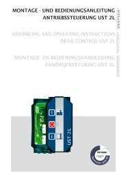
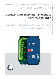
MONTAGE - UND BEDIENUNGSANLEITUNG<br />
ANTRIEBSSTEUERUNG UST 1L<br />
D E U T S C H<br />
ASSEMBLING AND OPERATING INSTRUCTIONS<br />
DRIVE CONTROL UST 1L<br />
E N G L I S H<br />
MONTAGE- EN BEDIENINGSHANDLEIDING<br />
AANDRIJFBESTURING UST 1L<br />
NEDERLANDS<br />
19
DRIVE CONTROL - UST 1L<br />
E N G L I S H<br />
20
DRIVE CONTROL - UST 1L<br />
G E N E R A L I T I E S<br />
The UST 1L is a gate control for roll-up gates and sectional gates with<br />
three phase motors or single-phase motors. All usual safety elements<br />
can be connected to. Additional possibilities of use are possible by<br />
adding different with different insert cards.<br />
To open or close a gate, the corresponding button of the cover<br />
respectively the outside button has to be actuated.<br />
In automatic operation mode, the gate is also able to be opened or<br />
closed by remote control.<br />
E N G L I S H<br />
F E A T U R E O F P E R F O R M A N C E<br />
The most important features of performance of UST 1L are:<br />
4easy operation and adjustment<br />
4weatherproof IP 54 (IP 65 on request)<br />
4big connexions space for wiring<br />
Most high safety by:<br />
4radio remote control 433 MHz / 868 MHz (optional)<br />
4conformity to the valid directives and norms<br />
4a wide range of safety elements are able to be connected<br />
U S E A C C O R D I N G T O P U R P O S E<br />
The Drive Control UST 1L is suitable for controlling industrial gates<br />
such as sectional, roll-up gates, multiple leaf doors and roll-up<br />
21
DRIVE CONTROL - UST 1L<br />
S A F E T Y I N S T R U C T I O N S<br />
E N G L I S H<br />
If following safety instructions are not respected,<br />
the company assembling the equipment will be<br />
responsible of the resulting damages to persons<br />
and material.<br />
The company assembling the equipment is responsible of the complete<br />
equipment. He has to care for the respect of the relevant norms and<br />
directives (such as DIN 1986, EN 12050). He is responsible of the<br />
establishment of the technical documentation of the complete equipment<br />
which must be enclosed to the equipment.<br />
This sign in the description of the control points<br />
out to a possible danger that is explained in details<br />
in this description.<br />
Installation, use and operation of control that is contrary to these<br />
operating instructions or the technical specifications given inside<br />
lead to endanger persons and result to an exclusion of liability and<br />
warranty.<br />
National and local regulations and norms related to the installation as<br />
well as Regulations for Prevention of Accidents of the German<br />
Employer's Liability Insurance Association are to be respected.<br />
Installation and maintenance works should only be done by specialised<br />
personnel who are trained for.<br />
During works at the gate, it has absolutely to be cut off from power<br />
supply.<br />
Dead man operation mode of a gate is only permitted if the gate is<br />
visible from the operating devices.<br />
22
DRIVE CONTROL - UST 1L<br />
D E A R C U S T O M E R S !<br />
You have decided in favour of a high quality product.<br />
In production, we applied the most possible care to dispatch this<br />
control in a perfect state. Nevertheless, if you still experience a<br />
case that is subject to claim, so please send this control unit to us,<br />
directly to the plant with the details on a short description of<br />
faults.<br />
The range of guaranty only concerns trouble shooting of functions'<br />
errors on equipment that result from production's fault respectively<br />
material fault, including necessary spare parts needed for the purpose.<br />
E N G L I S H<br />
Before starting to install the control unit, please carefully<br />
read these operating instructions first.<br />
If changes in construction or improper installation were done or<br />
charged to be done other than our set directions of assembling without<br />
our previous written agreement, so we are free of liability of warranty<br />
and guaranty of product.<br />
The assembling company should take care that EMV directions, directions<br />
of product's construction are respected.<br />
WARNING!<br />
The control unit should not be used in the explosive area.<br />
CAUTION!<br />
Connect the mains cable to the screw terminal X1 (L1, L2, L3)<br />
and the screw terminal PE to the mother board.<br />
The mains cable must be protected by fuse 3 x 6A<br />
and/or 3 x 10A at the building side.<br />
The value of protection fuse has to be chosen the way<br />
that it is activated by a blocked motor.<br />
23
DRIVE CONTROL - UST 1L<br />
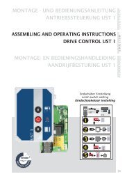
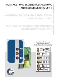
D E S C R I P T I O N<br />
Plug-in strip of modules<br />
Terminal screw<br />
of antenna<br />
Setting key OPEN<br />
Setting key CLOSE<br />
E N G L I S H<br />
Plug-in strip<br />
of radio<br />
Plug-in strip<br />
of brake relay<br />
Plug-in terminal<br />
of safety<br />
elements<br />
Plug-in<br />
terminal of<br />
limit switch<br />
Plug-in strip<br />
of triple switch<br />
Plug-in terminal<br />
of passing<br />
through<br />
light barrier<br />
Plug-in strip<br />
of key<br />
operated switch<br />
Plug-in terminal<br />
of instruction<br />
switch<br />
Terminal screw<br />
PE<br />
Plug-in terminal<br />
of mains<br />
Plug-in<br />
terminal<br />
of motor<br />
24<br />
LED (green)<br />
limit switch DOWN,<br />
is on in case of<br />
disturbance<br />
LED (green)<br />
limit switch UP,<br />
is on in case of<br />
disturbance<br />
LED (red)<br />
safety circuit STOP,<br />
is off in case of<br />
disturbance<br />
LED (red)<br />
in case of disturbance,<br />
the light barrier is off<br />
LED (green)<br />
gate DOWN, is on when<br />
the button is activated<br />
LED (yellow)<br />
Impulse, is on when<br />
the button is activated<br />
LED (green)<br />
gate UP, is on when<br />
the button is activated
DRIVE CONTROL - UST 1L<br />
D E S C R I P T I O N O F E Q U I P M E N T<br />
O P E R A T I N G E L E M E N T S<br />
The gate is activated to move in OPEN or CLOSED position by the push<br />
button installed in the cover of impulse respectively dead-man<br />
operation mode OPEN or CLOSED. If the gate is moving in impulse<br />
operation mode, the gate can be stopped by the STOP button at any time.<br />
Additional operating elements such as triple push buttons are able to<br />
be connected for operation from outside.<br />
A traction switch (ceiling traction switch) assembled inside and/or<br />
outside controls the gate in the function.<br />
OPEN-STOP-CLOSE (only if module K2 is used).<br />
If a receiver 433 MHz / 868 MHz is plugged (optionally), stopping the<br />
gate by means of radio hand-held transmitter is always possible.<br />
E N G L I S H<br />
C O N N E X I O N M A I N S C A B L E<br />
A 16A CEE plug is connected to the screw<br />
terminal L1, L2, L3 and PE.<br />
The mains supply to <strong>UST1</strong> can also occur<br />
with an optional three phase main switch.<br />
In this case, the CEE plug is took off<br />
during assembling.<br />
PE<br />
X1 L1 L2 L3<br />
16 A CEE plug<br />
of supply line<br />
C O N N E X I O N T H R E E P H A S E D R I V E S<br />
The three phase drive is connected to the<br />
screw terminal U, V, W and PE. If the<br />
drive is equipped with an N line, so it<br />
will be connected at the loose screw<br />
terminal N from the main supply.<br />
For example: for a brake that is operated<br />
to 230 V through a rectifier.<br />
PE<br />
X2<br />
U V W<br />
M<br />
3~<br />
Motor<br />
J U M P E R B R I D G E S<br />
In case of basic drive, a jumper is plugged in the plugs X11 (Pin 5/6),<br />
X3A(Pin 1/2) and X3B (Pin 1/2).<br />
25
DRIVE CONTROL - UST 1L<br />
E N G L I S H<br />
C O N T R O L O F T U R N I N G D I R E C T I O N<br />
After connexion of drives, the turning direction in dead man mode of<br />
operation must be checked with the buttons OPEN and CLOSED.<br />
If the direction does not correspond to the direction of the arrow of<br />
the pushed button, the CEE plug must be pulled out and the U and V<br />
connexions must be exchanged (phase inverter).<br />
Caution, mind the limit switch!<br />
C O N N E X I O N O F L I M I T S W I T C H ( L S )<br />
In case of UST 1L, both limit switches OPEN and CLOSED are connected as<br />
contacts free of potential to the screw terminal J20 and J19 of the<br />
terminal block x5. The safety circuit with the integrated safety limit<br />
switch is connected to the screw terminal J22 of the terminal block x5.<br />
In case of UST 1L, it is possible to connect a second additional limit<br />
switch switch up (J26 x 4B) to choose between two different OPEN<br />
positions (summer / winter adjustments) through a position switch on<br />
the housing cover (optional) of the UST 1L.<br />
Adjustments of limit switch have to be done in dead man operation mode!<br />
Thermo<br />
Emergency<br />
crank handle<br />
X5<br />
Pre-LS<br />
LS-UP<br />
LS-DOWN<br />
J22 J21 J20 J19<br />
J32<br />
+ B A<br />
J33<br />
Thermo PRE-LS STOP STOP 12V DC RS485<br />
CLOSED totally CLOSED<br />
OPEN<br />
-<br />
X4b<br />
SKS STOP<br />
or DW half OPEN<br />
J25 J26<br />
5 6 7 8<br />
LShalf<br />
height<br />
The modules K2 and K4 are absolutely necessary to operate with EES<br />
(Electronic limit switch optional). Please find the description of<br />
adjustment and programming of EES limit switch in the operating<br />
instructions of module K4.<br />
26<br />
A U T O M A T I C C L O S I N G<br />
( o p t i o n a l , o n l y i n a d d i t i o n w i t h m o d u l e K 2 )<br />
The function automatic closing has to be set at the rotary switch of<br />
position.<br />
If the function automatic closing is activated, the gate is closing<br />
again after the time set at the rotary switch from the final position.<br />
By actuating the stop button or a safety device, the automatic closing<br />
is blocked.
DRIVE CONTROL - UST 1L<br />
C O N N E X I O N O F A N O P T O E L E C T R O N I C S A F E T Y B A R<br />
( o p t i o n a l , o n l y i n a d d i t i o n w i t h m o d u l e K 2 )<br />
The optoelectronic safety bar is<br />
structured the way that a ray of<br />
light is interrupted by operating<br />
the rubber tube. To able to control<br />
a safety bar over the whole length,<br />
a receiver must be connected at the<br />
end of the switching bar.<br />
Connexion at the triple-pole screw<br />
terminal on the module K2<br />
+12V SIG 0V<br />
Optoelectronic<br />
safety bar OSE<br />
E N G L I S H<br />
For the event that the switching bar<br />
should be pressed on the floor, the<br />
reversing function is neutralised by<br />
connecting a prelimit switch<br />
(additional limit switch pre-LS) to<br />
the screw terminals J21 of the<br />
terminal box X5. In this case, the<br />
prelimit switch is adjusted 5 cm<br />
over the floor.<br />
brown<br />
green<br />
white<br />
Transmitter Receiver<br />
brown<br />
green<br />
white<br />
C O N N E X I O N O F T H E P I C K - U P O P E N , S T O P , C L O S E<br />
To operate from outside, a triple-pole push button can be connected to<br />
the terminal block X3 at the UST 1L. Here, both switches for OPEN and<br />
CLOSE should be performed as NO.<br />
Since the stop switch of the safety circuit is given away, it has to be<br />
connected as NC.<br />
Move the bridge on screw terminal J9 to connect the stop switch (NO) at the<br />
terminal block X3!<br />
Connexion of the operating elements<br />
OPEN, STOP, DOWN and IMPULS<br />
Connexion of a key switch<br />
Lock<br />
STOP OPEN Imp CLOSED<br />
Lock<br />
STOP OPEN Imp CLOSED<br />
X3<br />
J8 J9 J10 J11 J12<br />
1 2 3 4 5 6 7 8 9 10<br />
X3<br />
J8 J9 J10 J11 J12<br />
1 2 3 4 5 6 7 8 9 10<br />
Connexion of a triple-pole switch<br />
with four-conductor cable<br />
X3<br />
Lock STOP OPEN Imp CLOSED<br />
J8 J9 J10 J11 J12<br />
1 2 3 4 5 6 7 8 9 10<br />
27
DRIVE CONTROL - UST 1L<br />
E N G L I S H<br />
C O N N E X I O N O F A S A F E T Y B A R W I T H 8 . 2 k O h m<br />
( o p t i o n a l , o n l y i n a d d i t i o n w i t h m o d u l e K 2 )<br />
An electrical and/or a pneumatic electric safety bar can be directly<br />
connected to the UST 1L.<br />
The interpreter logic for the rubber tube is already integrated in the<br />
module K2. To be able to monitor the complete electronic circuit of the<br />
safety bar, the rubber tube must be connected with a resistance.<br />
The additional prelimit switch CLOSE is adjusted the way that the gate<br />
running downwards activates the prelimit switch 5 cm over the floor.<br />
The connexion of the rubber tube occurs at the screw terminal J25 of the terminal<br />
block X4b!<br />
CAUTION!<br />
Mind the position of the jumper on the module K2!<br />
C O N N E X I O N O F F U N C T I O N L I G H T B A R R I E R<br />
( o p t i o n a l , o n l y i n a d d i t i o n w i t h m o d u l e K 2 )<br />
A light barrier (at the terminal block X4a) can be connected directly<br />
to UST 1L to safe passing through. If the infrared ray is interrupted<br />
while the gate is closing, the gate stops and reverses to the upper<br />
final position.<br />
CAUTION:<br />
In case of a one-way light barrier (with only three points of connecting terminals),<br />
the switching contact and the Plus of the electronic device of the light barrier are<br />
connected to the screw terminal J24/3.<br />
While connecting the light barrier, move the bridge of J24 of block of screw<br />
terminal X4a!<br />
Connexion transmitter and<br />
receiver light barrier<br />
Foto<br />
J23 J24<br />
X4a<br />
1 2 3 4<br />
Connexion of<br />
reflection light barrier<br />
Foto<br />
J23 J24<br />
X4a<br />
1 2 3 4<br />
S<br />
E<br />
28<br />
S=Transmitter<br />
E=Receiver<br />
Safety<br />
light<br />
barrier<br />
Power<br />
supply<br />
24V DC<br />
Contact<br />
(NC)
DRIVE CONTROL - UST 1L<br />
C o n n e x i o n o f d i r e c t s a f e t y s w i t c h e s<br />
Safety elements which intervene directly in the control<br />
sequence are connected to the screw terminal J6 at the<br />
terminal block X2. Emergency shutdown and/or safety catch,<br />
feed protection and safety slip door count to them.<br />
C O N N E X I O N S A F E T Y S L I P D O O R<br />
( o p t i o n a l , o n l y i n a d d i t i o n w i t h m o d u l e K 2 )<br />
E N G L I S H<br />
In case of gates with a build-in slip door, the safety switch is<br />
connected to the screw terminal J6 at the terminal block X2.<br />
Caution! Move bridges (J6)!<br />
Slack rope switch/<br />
safety spring fracture<br />
or safety unroll<br />
X2<br />
U<br />
V<br />
W<br />
B1<br />
B2<br />
J1<br />
J6<br />
C O N N E X I O N O F P I C K - U P T R A C T I O N S W I T C H<br />
( o p t i o n a l , o n l y i n a d d i t i o n w i t h m o d u l e K 2 )<br />
In case of the control UST 1L, a ceiling traction switch (NO contact)<br />
can be connected to the screw terminal J11 at the terminal block X3,<br />
the function of this entry corresponds to the sequential phase control<br />
CLOSE-STOP-OPEN-STOP.<br />
X3<br />
Lock STOP OPEN Imp CLOSED<br />
J8 J9 J10 J11 J12<br />
1 2 3 4 5 6 7 8 9 10<br />
Traction<br />
switch<br />
29
DRIVE CONTROL - UST 1L<br />
R A D I O R E M O T E C O N T R O L<br />
E N G L I S H<br />
A plug-in place (x9) for a single-channel wireless receiver is on the<br />
control UST 1L. Please find other in the operating instructions<br />
receiver and hand-transmitter AM433/AM868.<br />
L E G E N D<br />
J1<br />
SW1<br />
SW2<br />
J26<br />
J20<br />
J22<br />
J19<br />
J21<br />
J8<br />
J6<br />
J9<br />
J10<br />
J11<br />
J12<br />
J24<br />
J25<br />
J26<br />
T1<br />
X1<br />
X2<br />
X3<br />
X3A<br />
X3B<br />
X4a<br />
X4b<br />
X5<br />
X8a<br />
X8b<br />
X9<br />
X11<br />
Motor<br />
Setting key OPEN<br />
Setting key CLOSE<br />
Additional limit switch OPEN (half opening height)<br />
Limit switch OPEN (NC)<br />
Safety circuit (NC)<br />
Limit switch CLOSE (NC)<br />
Additional limit switch CLOSE (prelimit switch)<br />
Emergency shut-down (NC)<br />
Slip door contact (NC) / feed protection<br />
STOP key (NC)<br />
OPEN key (NO)<br />
Impulse key (NO)<br />
CLOSE key (NO)<br />
Passing through light barrier (NC)<br />
Closing edge protection<br />
Limit switch HALF OPEN (NC)<br />
Transformer<br />
Terminal strip network<br />
Plug-in terminal motor<br />
Plug-in terminal pick-ups<br />
Plug-in strip for key operated switch<br />
Plug-in strip for triple switch<br />
Plug-in terminal passing through light barrier<br />
Plug-in terminal safety elements<br />
Plug-in terminal limit switch<br />
Plug-in strip for plug-in module (20 channels plug)<br />
Plug-in strip for plug-in module (10 channels plug)<br />
Plug-in strip for wireless receiver<br />
Plug-in strip for brake relay<br />
30
DRIVE CONTROL - UST 1L<br />
D I A G R A M O F C O N N E X I O N S<br />
X11<br />
X9 RADIO<br />
X8b<br />
ANTENNA<br />
UP<br />
DOWN<br />
Sw2 Sw1<br />
E N G L I S H<br />
M1<br />
B1<br />
STOP<br />
half OPEN<br />
J26<br />
B2<br />
SKS<br />
or DW<br />
J25<br />
5 6 7 8<br />
X4b<br />
LS-half height<br />
Safety bar<br />
LS-CLOSED<br />
LS-OPEN<br />
Pre-LS<br />
Thermo<br />
- + B A<br />
X5<br />
J22 J21 J20 J19 J32 J33<br />
X8a<br />
Transformer<br />
X3A X3B<br />
Foto<br />
J24<br />
3 4<br />
2<br />
1<br />
X4a<br />
Relay<br />
X2<br />
J6<br />
J1<br />
W V U<br />
J23<br />
J8 J9 J10 J11 J12<br />
X3 1 2 3 4 5 6 7 8 9 10<br />
Fuse<br />
T600mA<br />
L1 L2 L3<br />
PE PE PE<br />
3<br />
230V<br />
X1<br />
Emergency<br />
crack handle<br />
12V DC RS485<br />
STOP<br />
CLOSED<br />
STOP<br />
totally<br />
OPEN<br />
Thermo Pre-LS<br />
CLOSED<br />
LIMIT SWITCH<br />
Light barrier<br />
CLOSED<br />
IMPULS<br />
OPEN<br />
STOP<br />
Lock<br />
J4<br />
Relay<br />
31
DRIVE CONTROL - UST 1L<br />
T E C H N I C A L D A T A<br />
Model<br />
UST 1L<br />
E N G L I S H<br />
Power supply<br />
Motor connexion through relay<br />
Connecting terminal<br />
Ambient temperature<br />
Control voltage 24V DC<br />
Type of protection<br />
Dimension<br />
3x400V AC 50Hz (6 and/or 10A safe)<br />
2x3 NO relay contact,<br />
400V/max. 1,2kVA<br />
1,5 mm² max.<br />
-20°C to +60°C<br />
Fuse protection secondary 0,8A delayaction<br />
fuse<br />
IP 54 (IP 65 on request)<br />
255 x 120 x 180mm (BxHxD)<br />
32
DRIVE CONTROL - UST 1L<br />
E U M A N U F A C T U R E R ’ S D E C L A R A T I O N<br />
According to the machines' directive 98/37/EU annexe II B of the EU<br />
Herewith, the manufacturer:<br />
<strong>Mtec</strong> Gesellschaft für Antriebssysteme mbH<br />
Friethöfer Kamp 23<br />
D-48727 Billerbeck<br />
E N G L I S H<br />
declares that the product:<br />
D R I V E C O N T R O L U S T 1 L<br />
corresponds to the following directions of the EU:<br />
98/37/EG<br />
89/336/EWG<br />
73/23/EWG<br />
machines' directive (former 89/392/EWG)<br />
EMC directive (with changes 91/263/EWG, 92/31/EWG, 93/68/EWG)<br />
directive of low voltage (with changes 93/68/EWG)<br />
and following test certificate of conformity:<br />
Number 44 780 07 553313 - 001 of TÜV Nord CERT GmbH<br />
Following European norms/norm drafts were particularly applied:<br />
EN 12445:2001<br />
EN 12453:2001<br />
EN 12978:2003<br />
EN 13849-1:2006<br />
EN 60204-1:1997<br />
EN 60335-1:1994<br />
Safety use of motorised gates; testing processes<br />
Safety use of motorised gates; requirements<br />
Gates, safety installations, requirements and testing processes<br />
Machines' safety, control's parts related to safety<br />
Machines' safety; electrical equipment<br />
Safety of electrical devices; general requirements<br />
REMARK:<br />
The start up of the gate unit where this control should be installed in;<br />
is forbidden till it is ascertained that the gate unit corresponds to<br />
the directive 98/37/EG.<br />
Billerbeck, April 2005<br />
(Place, date)<br />
(Signature)<br />
Peter Menke, Managing Director<br />
(Name and function of signatory)<br />
33
DRIVE CONTROL - UST 1L<br />
O P T I O N A L A C C E S S O R Y<br />
E N G L I S H<br />
K1<br />
Module for impulse OPEN<br />
K1E<br />
Module for impulse OPEN<br />
electronic limit switch<br />
K2<br />
Module to connect a DW-strip,<br />
an SKS 8.2 kOhm or an<br />
OSE strip<br />
K3<br />
Module for two-way traffic<br />
control and test entering<br />
light barriers<br />
K4<br />
Module to connect an<br />
electronic limit switch<br />
K5<br />
Module for service display<br />
EK1-433 | EK1-868<br />
433 or 868 MHz wireless receiver AM<br />
FSK433 | FSK868<br />
Hand-held transmitter for the<br />
433 or 868 MHz wireless<br />
receiver AM<br />
34
COMMENTS<br />
E N G L I S H<br />
35
DRIVE CONTROL - UST 1L<br />
E N G L I S H<br />
Copyright.<br />
No part of this <strong>manual</strong> may be reproduced without our prior consent.<br />
Subject to changes which are in the interest of technical improvements.<br />
CONTACT<br />
36