A419ABG-3C Electronic Temperature Control Installation Instructions
A419ABG-3C Electronic Temperature Control Installation Instructions
A419ABG-3C Electronic Temperature Control Installation Instructions

You also want an ePaper? Increase the reach of your titles
YUMPU automatically turns print PDFs into web optimized ePapers that Google loves.
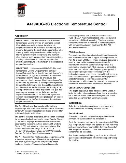
<strong>Installation</strong> <strong>Instructions</strong><br />
Issue Date April 21, 2014<br />
<strong>A419ABG</strong>-<strong>3C</strong> <strong>Electronic</strong> <strong>Temperature</strong> <strong>Control</strong><br />
Application<br />
IMPORTANT: Use this <strong>A419ABG</strong>-<strong>3C</strong> <strong>Electronic</strong><br />
<strong>Temperature</strong> <strong>Control</strong> only as an operating control.<br />
Where failure or malfunction of the electronic<br />
temperature control could lead to personal injury or<br />
property damage to the controlled equipment or other<br />
property, additional precautions must be designed<br />
into the control system. Incorporate and maintain<br />
other devices, such as supervisory or alarm systems<br />
or safety or limit controls, intended to warn of or<br />
protect against failure or malfunction of the electronic<br />
temperature control.<br />
IMPORTANT : Utiliser ce <strong>A419ABG</strong>-<strong>3C</strong> <strong>Electronic</strong><br />
<strong>Temperature</strong> <strong>Control</strong> uniquement en tant que<br />
dispositif de contrôle de fonctionnement. Lorsqu'une<br />
défaillance ou un dysfonctionnement du electronic<br />
temperature control risque de provoquer des<br />
blessures ou d'endommager l'équipement contrôlé<br />
ou un autre équipement, la conception du système<br />
de contrôle doit intégrer des dispositifs de protection<br />
supplémentaires. Veiller dans ce cas à intégrer de<br />
façon permanente d'autres dispositifs, tels que des<br />
systèmes de supervision ou d'alarme, ou des<br />
dispositifs de sécurité ou de limitation, ayant une<br />
fonction d'avertissement ou de protection en cas de<br />
défaillance ou de dysfonctionnement du electronic<br />
temperature control.<br />
The A419 <strong>Electronic</strong> <strong>Temperature</strong> <strong>Control</strong> is a<br />
single-stage, electronic temperature control. Pre-wired<br />
cords with plug and receptacle ends are provided for<br />
quick and simple installation.<br />
The control features a lockable, three-button touchpad<br />
for setup and adjustment and a Liquid Crystal Display<br />
(LCD) which displays the sensed temperature and<br />
other control functions. A front panel Light-Emitting<br />
Diode (LED) indicates the output relay status. The<br />
control has a setpoint range of -30 to 212°F<br />
(-34 to 100°C) and is available in 120 VAC models.<br />
See the Technical Specifications section.<br />
The A419 control has heating and cooling modes with<br />
adjustable setpoint and differential, an adjustable<br />
anti-short cycle delay, and a temperature offset<br />
(setback) function. The control provides remote<br />
sensing capability, and electronic accuracy in a<br />
Type NEMA 1 high-impact plastic enclosure suitable<br />
for surface or DIN rail mounting. The temperature<br />
sensor supplied with the control is interchangeable<br />
with compatible Johnson <strong>Control</strong>s/PENN® A99<br />
temperature sensors.<br />
FCC Compliance<br />
This equipment has been tested and found to comply<br />
with the limits for a Class A digital device pursuant to<br />
Part 15 of the FCC Rules. These limits are designed to<br />
provide reasonable protection against harmful<br />
interference when the equipment is operated in a<br />
commercial environment. This equipment generates,<br />
uses, and can radiate radio frequency energy and, if<br />
not installed and used in accordance with the<br />
instruction manual, may cause harmful interference to<br />
radio communications. Operation of this equipment in<br />
a residential area is likely to cause harmful<br />
interference, in which case the user will be required to<br />
correct the interference at his/her own expense.<br />
Canadian DOC Compliance<br />
This digital apparatus does not exceed the Class A<br />
limits for radio noise emissions from digital apparatus<br />
set out in the Radio Interference Regulations of the<br />
Canadian Department of Communications.<br />
<strong>Installation</strong><br />
Refer to the following guidelines, procedures and<br />
illustrations when installing an A419 control.<br />
Parts Included<br />
Pre-wired cords with plug and receptacle ends are<br />
provided for quick and simple installation.<br />
Each A419 control includes a Johnson <strong>Control</strong>s/PENN<br />
A99 temperature sensor. The sensor may be removed<br />
and replaced with any compatible Johnson <strong>Control</strong>s®<br />
A99 temperature sensor, or the wire leads on the<br />
sensor may be extended.<br />
See the Mounting and Wiring sections for additional<br />
guidelines and restrictions when mounting and wiring<br />
the control.<br />
© 2014 Johnson <strong>Control</strong>s, Inc. 1<br />
Part No. 24-7664-2543, Rev. A<br />
www.johnsoncontrols.com
Dimensions<br />
1/2<br />
(13)<br />
2-15/16<br />
(75)<br />
9/64<br />
(3.7)<br />
1-9/16<br />
(40)<br />
DIN<br />
Rail<br />
7/16<br />
(11)<br />
6 ft (1.8 m)<br />
Electrical Cords with<br />
Male and Female Plugs<br />
Mounting<br />
2-3/8<br />
(61)<br />
Sensor<br />
2<br />
(50)<br />
2-3/8<br />
(61)<br />
1/4<br />
(6)<br />
MENU<br />
Figure 1: Dimensions, in. (mm)<br />
Sensor<br />
Wire Lead<br />
6.6 ft<br />
(2 m)<br />
5<br />
(127)<br />
4<br />
(102)<br />
An A419 control has a standard high-impact plastic<br />
NEMA 1 enclosure. The A419 control is not position<br />
sensitive but should be mounted for convenient wiring<br />
and adjustment.<br />
Wiring<br />
Observe the following guidelines and refer to Figure 2<br />
and Table 1 when wiring the sensor to the<br />
A419 control.<br />
• Wire insulation rating must be 90°C, minimum.<br />
• <strong>Temperature</strong> sensor signals may be affected by<br />
electrical interference. When extending sensor<br />
cable beyond 50 ft (15.2 m), use a twisted-pair,<br />
shielded cable to reduce electrical interference.<br />
• A99 temperature sensors are not polarity<br />
sensitive. Wire the leads to (+) SEN and (-) COM<br />
on the sensor terminal block (TB3). See Figure 2.<br />
Keep the leads between the control and sensor as<br />
short as possible/practical in your application. The<br />
additional resistance in long sensor leads creates<br />
error between the actual temperature and the<br />
displayed temperature. Refer to Table 1 when<br />
extending sensor leads.<br />
Table 1: Maximum Recommended Sensor Cable<br />
Lengths and Wire Sizes<br />
Wire<br />
Gauge<br />
Maximum Sensor Cable Length*<br />
feet (meters)<br />
16 AWG 500 (150)<br />
18 AWG 300 (100)<br />
20 AWG 200 (60)<br />
22 AWG 125 (40)<br />
* At the listed maximum cable lengths, there is less<br />
than 1F° (0.6C°) error in the actual temperature vs.<br />
displayed temperature.<br />
!<br />
WARNING: Risk of Electric Shock.<br />
Disconnect or isolate all power supplies before<br />
making electrical connections. More than one<br />
disconnection or isolation may be required to<br />
completely de-energize equipment. Contact with<br />
components carrying hazardous voltage can cause<br />
electric shock and may result in severe personal<br />
injury or death.<br />
AVERTISSEMENT : Risque de décharge<br />
électrique. Débrancher ou isoler toute alimentation<br />
avant de réaliser un branchement électrique.<br />
Plusieurs isolations et débranchements sont<br />
peut-être nécessaires pour -couper entièrement<br />
l'alimentation de l'équipement. Tout contact avec<br />
des composants conducteurs de tensions<br />
dangereuses risque d'entraîner une décharge<br />
électrique et de provoquer des blessures graves,<br />
voire mortelles.<br />
(Optional)<br />
Binary<br />
Input<br />
Switch<br />
Cable<br />
Shield<br />
(if used)<br />
A99<br />
Sensor<br />
120 VAC<br />
Neutral<br />
TB3<br />
120 VAC Application<br />
TB1<br />
Not<br />
Used<br />
(+) BIN<br />
(–) COM<br />
(+) SEN<br />
AC COM<br />
120<br />
TB2<br />
<strong>A419ABG</strong>-3<br />
Not<br />
Used<br />
C<br />
NO<br />
Load<br />
Figure 2: Typical 120 VAC Application Wiring<br />
All wiring must conform to the National Electrical Code<br />
and local regulations.<br />
2 <strong>A419ABG</strong>-3 <strong>Electronic</strong> <strong>Temperature</strong> <strong>Control</strong> <strong>Installation</strong> <strong>Instructions</strong>
AC<br />
COM<br />
Not<br />
Used<br />
120<br />
Not<br />
Used<br />
C<br />
NO<br />
TB1<br />
TB2<br />
Male<br />
Plug<br />
Female<br />
Receptacle<br />
Figure 3: Factory Power Wiring<br />
Setup and Adjustments<br />
!<br />
WARNING: Risk of Electric Shock.<br />
Disconnect or isolate all power supplies before<br />
making electrical connections. More than one<br />
disconnection or isolation may be required to<br />
completely de-energize equipment. Contact with<br />
components carrying hazardous voltage can cause<br />
electric shock and may result in severe personal<br />
injury or death.<br />
AVERTISSEMENT : Risque de décharge<br />
électrique. Débrancher ou isoler toute alimentation<br />
avant de réaliser un branchement électrique.<br />
Plusieurs isolations et débranchements sont<br />
peut-être nécessaires pour -couper entièrement<br />
l'alimentation de l'équipement. Tout contact avec<br />
des composants conducteurs de tensions<br />
dangereuses risque d'entraîner une décharge<br />
électrique et de provoquer des blessures graves,<br />
voire mortelles.<br />
IMPORTANT: To ensure that the output relay<br />
operates as intended, verify that all three of the<br />
jumpers are positioned properly for the application<br />
before powering the A419 control.<br />
IMPORTANT: The touchpad cannot be<br />
unlocked without a jumper installed across the<br />
P5 jumper pins. Do not discard jumpers in case they<br />
are required in the future. See Figure 4 and<br />
Figure 5.<br />
Positioning the Jumpers<br />
The P5 jumper position determines if the touchpad is<br />
locked or unlocked.<br />
The P4 jumper pin block has two pairs of jumper pins.<br />
The top pair of pins (JUMP1) determines if the control<br />
is set for Heating or Cooling mode. The bottom pair of<br />
pins, (JUMP2) establishes whether Setpoint is at cut-in<br />
or at cutout. See Table 2 and Figure 5.<br />
<strong>A419ABG</strong>-3 <strong>Electronic</strong> <strong>Temperature</strong> <strong>Control</strong> <strong>Installation</strong> <strong>Instructions</strong> 3
To position a jumper in the Installed position, place<br />
the jumper on both pins, which closes the circuit<br />
between the pins. To position a jumper in the<br />
Removed position, place the jumper on one pin only.<br />
See Figure 4.<br />
Jumper<br />
Pins<br />
=<br />
Installed<br />
(Jumper Positioned on Both Pins)<br />
=<br />
Removed<br />
(Jumper Positioned on One Pin)<br />
Figure 4: Positioning the Jumpers<br />
Touchpad<br />
Locked<br />
P5<br />
JUMP2<br />
P4<br />
Heating Mode<br />
Cut-in at Setpoint<br />
Cooling Mode<br />
Cut-in at Setpoint<br />
Heating Mode<br />
Cut-out at Setpoint<br />
Cooling Mode<br />
Cut-out at Setpoint<br />
Figure 5: Jumper Positions and <strong>Control</strong> Settings<br />
The A419 <strong>Control</strong> Functions<br />
Setpoint (SP) establishes the temperature value at<br />
which the equipment is switched on or off, depending<br />
on the user selected mode of operation. Setpoint<br />
range is -30 to 212°F or -34 to 100°C (in 1-degree<br />
increments).<br />
If Setpoint mode is set to cut-in, setpoint is the<br />
temperature value at which the control closes the<br />
Normally Open (N.O.) contacts. If Setpoint mode is set<br />
to cutout, setpoint is the temperature at which the N.O.<br />
contacts open.<br />
Differential (dIF) establishes the difference in<br />
temperature between the cut-in value and cutout<br />
value. The differential is set relative to Setpoint and<br />
may be set from 1 to 30 F° or C° (in 1-degree<br />
increments).<br />
Anti-Short Cycle Delay (ASd) establishes the<br />
minimum time that the output relay remains<br />
de-energized before the next on-cycle. The ASd does<br />
not allow the output relay to re-energize until the<br />
programmed time delay has elapsed. The delay is<br />
activated when the control is first turned on and every<br />
time an on-cycle ends. When the delay is activated,<br />
the LCD alternately flashes the sensor temperature<br />
and ASd. The Anti-short Cycle Delay range is<br />
0 to 12 minutes (in 1-minute increments).<br />
Sensor Failure Operation (SF) establishes how the<br />
A419 control’s output-relay operates the equipment in<br />
the event of a sensor or sensor wiring failure. The user<br />
may select to run the equipment continuously or to<br />
shut it down. When the control detects a sensor circuit<br />
failure, the LCD flashes SF alternately with OP (if the<br />
sensor circuit is open), or SH (if the sensor circuit is<br />
shorted). Before indicating a failure, the control<br />
implements a 1-minute delay, which allows verification<br />
of failure condition and avoids nuisance failure<br />
indications.<br />
Table 2: Jumper Designations, Jumper Positions, and <strong>Control</strong> Settings<br />
Function<br />
Cooling/Heating<br />
Operating Mode<br />
Setpoint at<br />
Cut-in or Cutout<br />
Jumper Pins Designation<br />
on <strong>Control</strong><br />
JUMP1<br />
(Top Pair of Pins on Block P4)<br />
JUMP2<br />
(Bottom Pair of Pins on Block P4)<br />
Setting<br />
Cooling Mode<br />
Heating Mode<br />
Setpoint<br />
at Cut-in<br />
Setpoint<br />
at Cutout<br />
Jumper<br />
Position<br />
Removed<br />
Installed<br />
Removed<br />
Installed<br />
Touchpad Lock P5 Locked Removed<br />
Factory Default Setting<br />
(and Jumper Position)<br />
Cooling Mode<br />
(Jumper Removed)<br />
Cut-in<br />
(Jumper Removed)<br />
Unlocked<br />
(Jumper Installed)<br />
4 <strong>A419ABG</strong>-3 <strong>Electronic</strong> <strong>Temperature</strong> <strong>Control</strong> <strong>Installation</strong> <strong>Instructions</strong>
<strong>Temperature</strong> Offset (OFS) establishes a set<br />
secondary Setpoint and Differential values that may<br />
be invoked to control an application when a circuit is<br />
closed between the binary input (BIN) and common<br />
(COM) terminals (and BIN appears on the display).<br />
See Figure 6. Offset range is 0 to 50F° or C° (in<br />
1-degree increments). A typical application might use<br />
a switching time clock to invoke night-setback<br />
temperature settings.<br />
IMPORTANT: Make sure the Touchpad Lock<br />
jumper is installed (unlocked) before attempting to<br />
adjust the A419 control functions. See Figure 5.<br />
If no setup entry is made for 30 seconds, the control<br />
reverts to the (normal) temperature display.<br />
IMPORTANT: If MENU is not pressed after<br />
changing the setpoint value, the control reverts to<br />
the previously programmed setpoint value.<br />
BIN<br />
F<br />
<strong>Temperature</strong><br />
Offset Indicator<br />
<strong>Temperature</strong><br />
Units Indicator<br />
Operating Mode<br />
Indicator<br />
Changing the A419 <strong>Control</strong> <strong>Temperature</strong> Units<br />
The A419 control is factory set to display Fahrenheit<br />
temperature. To change to Celsius, press Up and<br />
Down (arrows) simultaneously. Press them again to<br />
display Fahrenheit units. Verify that the control is<br />
displaying the desired temperature units before setting<br />
the Setpoint.<br />
MENU<br />
Liquid Crystal<br />
Display<br />
MENU Button<br />
DOWN Arrow<br />
Button<br />
UP Arrow<br />
Button<br />
Setting the A419 <strong>Control</strong> Setpoint Value<br />
To view and adjust Setpoint, follow these steps:<br />
1. Press and hold MENU (about 2 seconds) until the<br />
display flashes SP.<br />
2. Press MENU again to display the existing setpoint<br />
value.<br />
3. Press Up or Down (arrows) to change the setpoint<br />
value.<br />
4. Press MENU again to save the new value. The<br />
display returns to the sensed temperature.<br />
Output Relay<br />
Status Indicator<br />
LED<br />
Figure 6: Liquid Crystal Display, Touchpad, and<br />
LED Indicator<br />
Table 3: Display Symbols, <strong>Control</strong> Function, Ranges, Units, Values, and Factory Settings<br />
Display<br />
Factory Set<br />
<strong>Control</strong> Function<br />
Range – Units/Value<br />
Symbol<br />
Value<br />
SP Setpoint* -30 to 212 – °F (-34 to 100 – °C) 30<br />
dIF Differential* 1 to 30 – (F° or C° in 1-degree increments) 5<br />
ASd Anti-short Cycle Delay 0 to 12 – (in 1-minute increments) 1<br />
OFS <strong>Temperature</strong> Offset 0 to 50 (F° or C° in 1-degree increments) 0<br />
SF<br />
Sensor Failure Operation<br />
(No range) – 0 = output relay de-energized<br />
1 = output relay energized<br />
1<br />
F or C <strong>Temperature</strong> Units (No range) – F° or C° F°<br />
BIN<br />
<strong>Temperature</strong> Offset Indicator<br />
(No range) – BIN is displayed and the A419 control<br />
operates on the secondary setpoints when the circuit<br />
between the BIN and COM terminals is closed.<br />
N/A<br />
or<br />
Cooling or Heating Mode of<br />
Operation<br />
(No range) – (Cooling Mode) is displayed when the<br />
Jump1 jumper is removed. (Heating Mode) is displayed<br />
when the Jump1 jumper is installed.<br />
Cooling Mode<br />
* The sum of the Setpoint and Differential values must be within the Setpoint range, or the control may not function<br />
properly.<br />
<strong>A419ABG</strong>-3 <strong>Electronic</strong> <strong>Temperature</strong> <strong>Control</strong> <strong>Installation</strong> <strong>Instructions</strong> 5
Setting the Other A419 <strong>Control</strong> Functions<br />
To set the Differential, Anti-short Cycle Delay,<br />
<strong>Temperature</strong> Offset, or Sensor Failure operation, use<br />
the following method:<br />
1. Press and hold MENU until the display changes to<br />
flashing SP. (This takes about 2 seconds.)<br />
2. Press Up or Down (arrows) repeatedly until the<br />
desired function is displayed. (See Figure 6.)<br />
3. Press MENU to display the function’s current<br />
value.<br />
4. Press Up or Down (arrows) until the desired value<br />
is displayed.<br />
5. Press MENU to save the new value. The display<br />
returns to the sensor temperature.<br />
IMPORTANT: If MENU is not pressed after<br />
changing the settings, the new settings are not<br />
saved and the control reverts to the previously<br />
programmed setting values.<br />
Note: If no setup entry is made for 30 seconds, the<br />
control reverts to the (normal) temperature display.<br />
Note: Any saved A419 control settings are<br />
non-volatile and remain in the control’s memory<br />
during power interruptions.<br />
IMPORTANT: Do not set Setpoint and<br />
Differential values which (when totaled) fall out of<br />
A419 control’s Setpoint range (-30 to 212°F<br />
[-34 to 100°C]). The control will not function properly<br />
if Cut-in or Cutout values are outside of the control’s<br />
Setpoint range.<br />
Checkout<br />
Before applying power, make sure installation and wire<br />
connections are correct for your application. Then<br />
power, operate, and observe the system and A419<br />
control for at least three complete operating cycles<br />
before leaving the installation.<br />
Troubleshooting<br />
!<br />
WARNING: Risk of Electric Shock.<br />
Do not touch any exposed metal parts with anything<br />
other than properly insulated tools or insulated<br />
probes of the digital voltage meter. Failure to use<br />
properly insulated tools and probes may result in<br />
severe personal injuries or death.<br />
AVERTISSEMENT : Risque de décharge<br />
électrique. Ne jamais toucher une partie métallique<br />
exposée avec tout élément autre que des outils<br />
correctement isolés ou les sondes isolées du<br />
voltmètre numérique. L'utilisation d'outils et de<br />
sondes incorrectement isolés risque de provoquer<br />
des blessures graves, voire mortelles.<br />
If the control system does not function properly, verify<br />
that the control is wired, and set up properly. If the<br />
problem persists, use the following procedures to<br />
determine the cause of the problem:<br />
IMPORTANT: Follow these troubleshooting<br />
procedures in the order presented. Do not skip any<br />
of the steps in the procedures.<br />
1. Check for proper voltage to the A419 control.<br />
a. Remove the cover by loosening the four<br />
captive cover screws.<br />
b. Use a reliable AC voltmeter to check the<br />
voltage between the COM and 120V terminals<br />
on terminal block TB1. Refer to Figure 2.<br />
c. The voltage must be between 102 and<br />
132 VAC for 120 VAC applications.<br />
d. If the voltage reading is not within the required<br />
range, check the power source and input<br />
power wires for problems.<br />
2. Check for proper sensor operation.<br />
a. Disconnect all power sources to control.<br />
b. Using an accurate thermometer, take a<br />
temperature reading at the sensor location.<br />
c. Disconnect the sensor from the control.<br />
d. Using an ohmmeter, measure the resistance<br />
across the two sensor leads while the sensor<br />
is at the temperature taken in Step 2b.<br />
e. Consult Figure 7 to verify that the measured<br />
temperature and resistance conform to<br />
established temperature and resistance<br />
values.<br />
6 <strong>A419ABG</strong>-3 <strong>Electronic</strong> <strong>Temperature</strong> <strong>Control</strong> <strong>Installation</strong> <strong>Instructions</strong>
f. If the measured values conform to the values<br />
in Figure 7, proceed to Step 3.<br />
g. If the sensor’s measured resistance value is<br />
substantially different from the expected<br />
value for that temperature, check the sensor<br />
wiring. If sensor wiring is okay, replace the<br />
sensor.<br />
<strong>Temperature</strong> (°F)<br />
<strong>Temperature</strong> (°C)<br />
260<br />
240<br />
220<br />
200<br />
120<br />
100<br />
180<br />
160<br />
80<br />
140<br />
60<br />
120<br />
100<br />
40<br />
80<br />
60<br />
20<br />
40<br />
20<br />
0<br />
0<br />
-20<br />
-20<br />
-40<br />
-40<br />
500 700 900 1100 1300 1500 1700 1900 2100<br />
Resistance in Ohms<br />
Figure 7: <strong>Temperature</strong> vs. Sensor Resistance<br />
3. Check the A419 for proper operation.<br />
Note: Perform Troubleshooting Steps 1 and 2 before<br />
performing this step.<br />
a. Disconnect the load from the output relay<br />
terminals.<br />
b. Ensure that the Touchpad Lock jumper is<br />
installed, so that the touchpad is unlocked.<br />
c. Reconnect the sensor leads and supply<br />
power to the control.<br />
d. Replace the cover.<br />
e. Check the control settings for proper values.<br />
f. Press and hold MENU until Setpoint<br />
appears. (This takes about 2 seconds.)<br />
g. Press the Up and Down (arrows) to change<br />
the Setpoint temperature above and below<br />
the sensor temperature until the relay<br />
energizes and de-energizes as shown in<br />
Figure 7.<br />
Note: If the anti-short cycle delay has a set<br />
delay-time value greater than 0 minutes when the<br />
control is powered On, the relay does not energize<br />
until the time delay has elapsed.<br />
h. If the output relay does not perform as<br />
indicated in Figure 7, replace the A419 control.<br />
i. If proper operation of the A419 control is<br />
verified, reconnect the load and consult the<br />
equipment manufacturer’s instructions for<br />
troubleshooting the controlled equipment.<br />
Fault Codes<br />
If the LCD displays an alarm or fault code (SF or EE),<br />
consult Table 5 for explanation.<br />
Table 4: A419 Output Relay Operation in Different Operating Modes<br />
Setpoint<br />
Mode<br />
Cutout<br />
Cut-in<br />
Operating<br />
Mode<br />
Output Relay Is Energized (closing<br />
the NO and COM contacts) at…<br />
Output Relay Is De-Energized (opening<br />
the NO and COM contacts) at…<br />
Cooling Setpoint plus differential Setpoint<br />
Heating Setpoint minus differential Setpoint<br />
Cooling Setpoint Setpoint minus differential<br />
Heating Setpoint Setpoint plus differential<br />
Table 5: Fault Codes Defined<br />
Fault Code Definition System Status Solution<br />
SF flashing alternately<br />
with OP<br />
SF flashing alternately<br />
with SH<br />
Open temperature<br />
sensor or sensor wiring<br />
Shorted temperature<br />
sensor or sensor wiring<br />
EE Program failure Output is off<br />
Output functions according to<br />
the selected sensor failure mode<br />
(SF setting)<br />
Output functions according to<br />
the selected sensor failure mode<br />
(SF setting)<br />
See Troubleshooting section.<br />
Cycle power to reset the control.<br />
See Troubleshooting section.<br />
Cycle power to reset the control.<br />
Reset the control by pressing<br />
MENU. If problems persist, replace<br />
the control.<br />
<strong>A419ABG</strong>-3 <strong>Electronic</strong> <strong>Temperature</strong> <strong>Control</strong> <strong>Installation</strong> <strong>Instructions</strong> 7
Repairs and Replacement<br />
Do not attempt to repair or recalibrate the<br />
A419 temperature control. In case of a defective or<br />
improperly functioning control, contact your nearest<br />
Authorized Johnson <strong>Control</strong>s/PENN distributor or<br />
sales representative.<br />
Ordering Information<br />
Refer to Table 6 to order sensors, mounting hardware<br />
and other accessories used to install A419 controls.<br />
Contact your nearest Johnson <strong>Control</strong>s/PENN<br />
distributor or sales representative to order these<br />
products.<br />
When contacting your Johnson <strong>Control</strong>s/PENN<br />
distributor, have the model number of the control<br />
available. This number can be found on the label<br />
inside the cover of the control.<br />
Table 6: A419 <strong>Control</strong>s Accessories<br />
Product Code Number Description<br />
A99BB-200<br />
<strong>Temperature</strong> Sensor: PTC Sensor with 6-1/2 ft (2 m) Non-shielded 2-Wire Lead<br />
BKT287-1R<br />
DIN Rail: 12 in. (305 mm) long<br />
BKT287-2R<br />
DIN Rail: 36 in. (914 mm) long<br />
PLT344-1R<br />
End Clamps for DIN Rail Mounting<br />
CLK350-2C<br />
7-Day Programmable Digital Clock for activating Binary Offset<br />
WEL11A-601C<br />
Immersion Well for Mounting Sensor in Liquid Applications<br />
Technical Specifications<br />
Product<br />
Setpoint Range<br />
Differential Range<br />
Supply Voltage<br />
Power Consumption<br />
SPST Output Relay<br />
Contacts Electrical<br />
Ratings<br />
<strong>A419ABG</strong>-<strong>3C</strong> <strong>Electronic</strong> <strong>Temperature</strong> <strong>Control</strong><br />
-30 to 212°F (-34 to 100°C)<br />
1 to 30F° (1 to 30C°)<br />
120 VAC, 60 Hz<br />
1.8 VA Maximum<br />
Full Load Amperes N.O.: 12 A<br />
Locked Rotor Amperes N.O. : 72 A<br />
Non-inductive Amperes N.O.: 10 A<br />
Pilot Duty:<br />
125 VA @ 120 VAC<br />
Sensor Type PTC Sensor with 6.6 ft (2.0 m) leads<br />
<strong>Control</strong> Ambient Operating: -30 to 140°F (-34 to 60°C)<br />
<strong>Temperature</strong><br />
Shipping: -40 to 185°F (-40 to 85°C)<br />
Ambient Humidity 0 to 95% RH Noncondensing; Maximum Dew Point: 85°F (29°C)<br />
<strong>Control</strong> Enclosure Material Case and Cover: NEMA 1 - High-Impact Thermoplastic<br />
Agency Listings UL: File E27734; CCN’s XAPX (US), XAPX7 (Canada)<br />
FCC: CFR 47, Part 15, Class A. DOC, Class A<br />
The performance specifications are nominal and conform to acceptable industry standards. For application at conditions beyond these<br />
specifications, contact Application Engineering at 1-800-275-5676. Johnson <strong>Control</strong>s, Inc. shall not be liable for damages resulting from<br />
misapplication or misuse of its products.<br />
Building Efficiency<br />
507 E. Michigan Street, Milwaukee, WI 53202<br />
® Johnson <strong>Control</strong>s and PENN are registered trademarks of Johnson <strong>Control</strong>s, Inc. in the<br />
United States of America and/or other countries. All other trademarks used herein are the property<br />
of their respective owners. © Copyright 2014 by Johnson <strong>Control</strong>s, Inc. All rights reserved.<br />
8 <strong>A419ABG</strong>-3 <strong>Electronic</strong> <strong>Temperature</strong> <strong>Control</strong> <strong>Installation</strong> <strong>Instructions</strong>