Model 1011 Type Z Purge/Pressurization System - ISC Enclosure ...
Model 1011 Type Z Purge/Pressurization System - ISC Enclosure ...
Model 1011 Type Z Purge/Pressurization System - ISC Enclosure ...

Create successful ePaper yourself
Turn your PDF publications into a flip-book with our unique Google optimized e-Paper software.
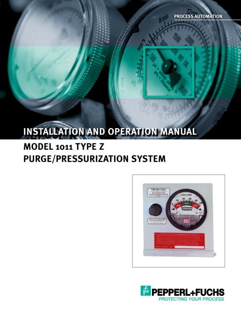
PROCESS AUTOMATION<br />
INSTALLATION AND OPERATION MANUAL<br />
MODEL <strong>1011</strong> TYPE Z<br />
PURGE/PRESSURIZATION SYSTEM
<strong>Model</strong> <strong>1011</strong> Installation and Operation Manual<br />
Page 2<br />
Page 3<br />
Page 3<br />
Page 4<br />
Page 5<br />
Page 6<br />
Page 7<br />
Page 8<br />
Page 9<br />
Table of Contents<br />
<strong>System</strong> Purpose and Description<br />
Purpose, <strong>System</strong> description, Important notes<br />
Identifying Your <strong>System</strong><br />
Defines specific features of the system<br />
General Information<br />
<strong>System</strong> & material specifications, <strong>System</strong><br />
accessories, Spare parts, Tools & test equipment<br />
<strong>Enclosure</strong> and Device Design<br />
Design requirements, Adjacent enclosures, Device<br />
ventilation, Temperature limitations<br />
Installation Overview<br />
Installation diagram<br />
Getting Started<br />
Establishing connection sizes, Determining enclosure<br />
inlet & outlet connection locations<br />
<strong>System</strong> Mounting<br />
LH, RH, TM, BM & WM configurations,<br />
FM & PM configurations<br />
Mounting Plate Dimensions<br />
Mounting plate dimension diagrams<br />
Hardware Mounting<br />
Optional enclosure protection vent, Warning<br />
nameplates<br />
Page 10 Pneumatic Tubing Requirements<br />
Protective gas supply requirements, Pneumatic<br />
connection requirements<br />
Page 11 Tubing Installation<br />
LH, RH, TM, BM, WM, FM & PM tubing<br />
configurations<br />
Page 12 Tubing Connection Diagrams<br />
LH, RH, TM, BM, WM, FM, & PM configuration<br />
connection points, Pneumatic diagram<br />
Page 13 Electrical Supply Requirements<br />
Wiring requirements, <strong>Enclosure</strong> power & alarm signal,<br />
<strong>Enclosure</strong> wiring methods & connections<br />
Page 14 Set-Up Procedure<br />
Class I & Class II set-up<br />
Page 15 Operating Sequence<br />
Class I & Class II operation<br />
Page 16 Troubleshooting Procedures<br />
Troubleshooting chart<br />
Page 17 Warranty and Liability Statement<br />
Warranty notes, General terms, Limitations<br />
Page 18 <strong>System</strong> Maintenance<br />
Regular maintenance, Long-term maintenance,<br />
Maintenance schedule<br />
Page 19 <strong>System</strong>s Identification & Application Information<br />
Purpose<br />
Purpose and Description<br />
Pepperl+Fuchs <strong>Enclosure</strong> Protection <strong>System</strong>’s purpose is to<br />
allow the use of general purpose or non-rated electrical or<br />
electronic devices, with exception to devices which produce<br />
excessive heat, utilize combustible gas, or expose arcing<br />
contacts to the hazardous atmosphere, in <strong>Type</strong> 4 or 12<br />
enclosures in the place of explosion proof <strong>Type</strong> 7 enclosures.<br />
Other purposes include heat, moisture and dust contamination<br />
prevention.<br />
Description<br />
<strong>Model</strong> <strong>1011</strong> is an enclosure pressurization or purging<br />
system that operates on a supply of compressed instrument<br />
air or inert gas. It regulates and monitors pressure within<br />
sealed (protected) enclosures, to prevent combustible dust<br />
accumulation or remove and prevent flammable gas or vapor<br />
accumulations. In Class II areas, the system maintains a “safe”<br />
(1.0") pressure. In Class I areas, the system accomplishes four<br />
air exchanges and maintains a “safe” (0.25") pressure. These<br />
processes reduce the hazardous (classified) area rating within<br />
the enclosure(s), in accordance with the NEC - NFPA 70, Article<br />
500, NFPA 496 and ISA12.4<br />
Important Notes<br />
One (1) permanent file copy and one (1) operations copy of<br />
this Manual must be studied and retained by the operator of<br />
this <strong>System</strong>. User’s Agents are responsible for transferring this<br />
Manual to the user, prior to start-up.<br />
The contents of this manual have been arranged to allow the<br />
use of this product as a stand-alone device on equipment and<br />
enclosures supplied by the user or its agents. The manual’s<br />
parameters encompass a combination of both National Fire<br />
Protection Association (NFPA) requirements and Pepperl+Fuchs<br />
requirements. Pepperl+Fuchs therefore acknowledges the<br />
use of NFPA 496 as a guideline, that we have enhanced<br />
certain NFPA requirements and that additional information<br />
has been compiled to complete this document. The manual is<br />
intended as a complete guide and must be considered, unless<br />
specifically stated otherwise, that all directives contained herein<br />
are Pepperl+Fuchs requirements for safe, practical and efficient<br />
use of this product.<br />
This system is not intended for use to protect enclosures or<br />
devices which contain ignitable concentrations of gases or<br />
vapors. This exclusion generally applies to process or product<br />
analyzing systems equipment.<br />
All specifications are subject to change without notice.<br />
Part No. 512083 Drawing No. 129-0205a 03/09<br />
2<br />
Subject to modifications without notice<br />
Pepperl+Fuchs Group<br />
www.pepperl-fuchs.com<br />
USA: +1 330 486 0002<br />
pa-info@us.pepperl-fuchs.com<br />
Germany: +49 621 776 2222<br />
pa-info@de.pepperl-fuchs.com<br />
Copyright Pepperl+Fuchs<br />
Singapore: +65 6779 9091<br />
pa-info@sg.pepperl-fuchs.com
<strong>Model</strong> <strong>1011</strong> Installation and Operation Manual<br />
Part No. 512083 Drawing No. 129-0205a 03/09<br />
Identifying Your <strong>System</strong><br />
This enclosure protection system is offered in various styles.<br />
For proper installation and operation, examine the system<br />
model number nameplate to identify the system style, area<br />
classification, and type, as noted below.<br />
1.00<br />
2.50<br />
<strong>Model</strong> <strong>1011</strong> CII <strong>Type</strong> Z<br />
10 CUBIC FEET MAXIMUM ENCLOSURE VOLUME<br />
CLASS II, DIVISION 2, GROUPS F & G TO NONHAZARDOUS<br />
CLASSIFIED<br />
®<br />
PURGE CONTROL FOR USE<br />
IN HAZARDOUS LOCATIONS<br />
CLASSIFIED BY UNDERWRITERS LABORATORIES INC.® IN ACCORDANCE<br />
WITH THE NATIONAL FIRE PROTECTION ASSOCIATION STANDARD FOR<br />
In order to comply with the NFPA 496 standard requiring<br />
protection against over pressurization of the protected<br />
enclosure, the installer must install one of the following items<br />
in addition to the enclosure protection system.<br />
a) Install an enclosure protection venon the protected<br />
FORMATION: enclosure.<br />
b) Install a tamperproof regulator upstream of the enclosure<br />
IAL: 0.12” ALUMINUM protection system's system supply inlet to pre-regulate<br />
IAL: N/A protective gas supply to 5 psi max.<br />
: WHITE BACKGROUND WITH BLACK COPY AND BORDER<br />
FORMATION PERTAINING TO PRINT FONTS,<br />
SIONS AND COLOR SCHEMES ARE CONTAINED IN<br />
OREL DRAW (.CDR) FILENAME UNDER DRAWING<br />
R 125-0916<br />
kument enthält sicherheitsrelevante Angaben. Es darf nicht ohne Absprache mit dem Normenfachmann geändert werden!<br />
document contains safety-relevant information. It must not be altered without the authorization of the norm expert!<br />
to ISO 16016 Only valid as long as released in EDM or with a valid production documentation!<br />
scale: 1:1 date: 2004-MAR-11<br />
change notice. respons. US.JMB<br />
Subject Labels to modifications and Mounting without Plate notice<br />
Copyright Pepperl+Fuchs<br />
Pepperl+Fuchs for MODEL Group <strong>1011</strong>-CII <strong>Type</strong> ZUSA: +1 330 486 0002 Germany: +49 621 776 approved<br />
125-0916<br />
2222 US.SSJ Singapore: +65 6779 9091<br />
g<br />
www.pepperl-fuchs.com pa-info@us.pepperl-fuchs.com pa-info@de.pepperl-fuchs.com norm pa-info@sg.pepperl-fuchs.com<br />
US.WDB sheet 3 of 5<br />
In addition, for small, tightly sealed enclosures, or to<br />
compensate for a fluctuating protective gas supply, it may<br />
be necessary to pre-regulate the protective gas supply to a<br />
constant 5 psi regardless of whether an enclosure protection<br />
ven is installed. This will reduce the amount of "drifting"<br />
that can normally occur when maintaining a "Safe" pressure<br />
inside a protected enclosure. The pre-regulation can be<br />
accomplished by installing a TR-10G tamperproof regulator<br />
accessories or equivalent.<br />
** <strong>Enclosure</strong> integrity determines actual flow rate<br />
Material Specifications<br />
PURGED AND PRESSURIZED ENCLOSURES FOR ELECTRICAL EQUIPMENT<br />
NFPA 496-1996<br />
Regulator body:<br />
Zinc w/ enamel finish, brass<br />
4S11<br />
Regulator handle:<br />
Polycarbonate<br />
<strong>1011</strong> - CI - Z - UH - ## <strong>Enclosure</strong> pressure gauge:<br />
Alum. w/ enamel finish<br />
Tube fittings:<br />
316 SS Forged body<br />
Series <strong>Model</strong> Number SCALE = 1X<br />
Tubing:<br />
316 SS 1/4" .035 welded<br />
Area Classificatio All dimensions are in inches.<br />
<strong>System</strong> nameplates: Silkscreen & Lexan<br />
CI - Class I Area<br />
®<br />
CII - Class All II outside Area corners R=0.1<br />
Fastener hardware:<br />
Aluminum & stainless steel<br />
<strong>System</strong> Tolerances: <strong>Type</strong> 2-place dec. +/- .01<br />
Mounting plate & bracket:<br />
Anodized aluminum<br />
Z - Div. 2 to Nonhazardous<br />
<strong>Enclosure</strong> warning nameplate:<br />
Silkscreened SS<br />
Mounting Configuratio<br />
Lexan ® is a registered trademark of the General Electric Corporation<br />
UM - universal mount<br />
FM - frame mount<br />
external surface<br />
external frame or rack<br />
Recommended Spare Parts<br />
PM - panel mount enclosure surface cutout<br />
Qty Description<br />
Part # (supercedes)<br />
## - Additional factory installed accessories<br />
1 <strong>Enclosure</strong> pressure indicator-CI 510023 (001000)<br />
FM & PM confi uration mounting plates include four (4) 1 <strong>Enclosure</strong> pressure indicator-CII 513235 (001027)<br />
1/4" mounting holes at each corner, on 5/16" centers.<br />
1 <strong>Enclosure</strong> pressure control regulator 513315 (002000)<br />
1 Installation & operation manual 129-0205<br />
1 <strong>Enclosure</strong> warning nameplate-CI 513008 (EWN-1)<br />
<strong>Model</strong> <strong>1011</strong> CII <strong>Type</strong> Z<br />
1 <strong>Enclosure</strong> warning nameplate-CII 513009 (EWN-2)<br />
10 CUBIC FEET MAXIMUM ENCLOSURE VOLUME<br />
General Information<br />
Please call and reference part number above for current spare<br />
CLASS II, DIVISION 2, GROUPS F & G TO NONHAZARDOUS<br />
parts pricing. Immediate pricing is available to all confirmed<br />
<strong>System</strong> Specifications PURGE CONTROL FOR USE customers.<br />
<strong>System</strong> dimensions: See Page 8<br />
®<br />
Shipping weight IN ( lbs.): HAZARDOUS LOCATIONS 7 Installation Tools & Testing Equipment<br />
CLASSIFIED Operating BYtemperature UNDERWRITERS range: LABORATORIES INC.® -20° IN F ACCORDANCE<br />
- 120° F 1/2" chuck drill<br />
WITHSupply THE NATIONAL pressure range: FIRE PROTECTION ASSOCIATION * 5 - 120 STANDARD psi max. FOR<br />
Supply requirements:<br />
Clean air or inert gas<br />
Complete set of drill bits<br />
PURGED AND PRESSURIZED ENCLOSURES FOR ELECTRICAL EQUIPMENT<br />
Safe pressure (CI/CII): NFPA 496-1996<br />
0.25" / 1.0" 1/2" conduit knockout punch or 0.875" hole saw<br />
Safe pressure flowrate: 4S11<br />
** 0.1-3.5 SCFH<br />
Complete set of tubing, conduit bending, instrument fitting and<br />
<strong>System</strong> supply fitting:<br />
1/4" tube fitting<br />
electrical craftsman hand tools<br />
<strong>Enclosure</strong> supply fitting:<br />
1/4" tube fitting<br />
<strong>Enclosure</strong> reference fitting:<br />
1/4" tube fitting 0 - 250 scfh flowmeter (connected upstream of the protection<br />
* With enclosure protection SCALE vent = - 120 2Xpsi<br />
maximum<br />
system to determine air consumption and flow during set-up<br />
Without enclosure protection ven - 5 psi maximum<br />
procedure)<br />
CLASSIFIED<br />
3
<strong>Model</strong> <strong>1011</strong> Installation and Operation Manual<br />
<strong>Model</strong> <strong>1011</strong> <strong>System</strong> Accessories<br />
Optional <strong>Enclosure</strong> Protection Vents<br />
EPV-1-SA-00<br />
Straight w/ spark arrestor<br />
EPV-1-SA-90<br />
Rt angle w/ spark arrestor<br />
Additional Items<br />
SMK-1, or -4<br />
<strong>System</strong> mounting kit<br />
EPSK-1<br />
Class I, Group C - D pressure switch kit<br />
EPSK-1A<br />
Class I, Group A - D pressure switch kit<br />
EPSK-2<br />
Class II, Group E - G pressure switch kit<br />
GPSK-1<br />
Class I, general-purpose switch kit<br />
GPSK-2<br />
Class II, general-purpose switch kit<br />
RAH<br />
Div. 1 remote alarm horn<br />
RAB-1<br />
Div. 1 remote alarm beacon<br />
RAB-2<br />
Div. 2 remote alarm beacon<br />
LCK<br />
L fitting conduit kit<br />
TCK<br />
T fitting conduit kit<br />
TR-10G<br />
Tamperproof regulator w/ gauge<br />
EFC-4<br />
1/4" flush connector<br />
EBC-4<br />
1/4" bulkhead connector<br />
EPC-10<br />
1/2" pipe connector<br />
ILF-4<br />
1/4" filter<br />
ETW<br />
<strong>Enclosure</strong> temperature warning<br />
<strong>Enclosure</strong> & Device Design<br />
<strong>Enclosure</strong> Design Requirements<br />
1. All windows must be shatterproof and sized as small as<br />
possible.<br />
2. All NFPA 496 required markings must be placed on or near<br />
all enclosure doors and covers.<br />
3. The enclosure must withstand an internal pressure of<br />
ten (10) inches of water without sustaining permanent<br />
deformation and resist all corrosive elements in the<br />
surrounding atmosphere.<br />
4. All lightweight objects in the enclosure, such as paper or<br />
insulation, must be firmly secured.<br />
5. The enclosure should be constructed from materials such as<br />
metal or nonstatic polycarbonate to meet or exceed NEMA<br />
4 or 12 performance requirements, but does not require<br />
third party approval.<br />
6. The installation of obstructions or other barriers that block<br />
or impede the flow of protective gas must be avoided.<br />
7. The creation of air pockets or other areas that trap<br />
flammable gases within the enclosure or devices must be<br />
avoided.<br />
8. The enclosure should be located in an area where impact<br />
hazards are minimal.<br />
9. If the enclosure is nonmetallic and contains equipment that<br />
utilizes or switches power loads greater than 2500 VA, it<br />
must be constructed from substantially noncombustible<br />
materials, such as materials designed to meet or exceed<br />
ANSI/UL94 ratings of 94 V-0 or 94 5V.<br />
Adjacent <strong>Enclosure</strong>s<br />
1. Adjacent enclosures must be protected by one of the<br />
following means:<br />
a) purged or pressurized in series with the protected<br />
enclosure<br />
b) purged or pressurized separately or<br />
c) protected by other means; e.g., explosion proof<br />
enclosures, hermetically sealed devices or intrinsic safe<br />
circuits<br />
2. Adjacent purged or pressurized enclosures must be<br />
designed to meet all construction requirements above.<br />
Total Volume Calculation<br />
1. The total volume of all pressurized enclosures, devices and<br />
wireways must be considered.<br />
2. All enclosure, device, and wireway volumes must be<br />
calculated without consideration of internally consumed<br />
space.<br />
Device Ventilation<br />
1. Enclosed devices within the protected enclosure that do not<br />
exceed 1.22 in 3 of free volume do not require ventilation to<br />
the protected enclosure.<br />
2. If the free volume of an internal device exceeds 1.22 in 3 it<br />
must be protected by one of the following means:<br />
a) ventilated on the top and bottom sides with 1 in 2 of<br />
opening for each 400 in 3 of volume within the internal<br />
protected enclosure, at a minimum diameter of 1/4"<br />
b) purged in series with the protected enclosure or be<br />
purged separately or<br />
c) protected by other means; e.g., explosion proof<br />
enclosures, hermetically sealed devices, or intrinsic safe<br />
circuits.<br />
Temperature Limitations<br />
1. The enclosure must have no surface area that exceeds 80<br />
percent of the flammable or ignitable substance’s autoignition<br />
temperature.<br />
2. Internal devices that exceed this temperature must be<br />
protected by one of the following manners:<br />
a) The device is enclosed in a chamber that is C UL US<br />
listed as a hermetically sealed device that prohibits the<br />
entrance of a flammable or ignitable substance, and<br />
maintains a surface temperature below temperature<br />
limits.<br />
b) It can be proven by testing that the devices will not ignite<br />
the substance involved.<br />
c) The device is purged in a separate enclosure that bears<br />
an ETW (enclosure temperature warning nameplate).<br />
Devices may be accessed only after power has been<br />
removed and the device has been allowed to cool to<br />
safe temperature, or the area is positively known to be<br />
nonhazardous.<br />
Part No. 512083 Drawing No. 129-0205a 03/09<br />
4<br />
Subject to modifications without notice<br />
Pepperl+Fuchs Group<br />
www.pepperl-fuchs.com<br />
USA: +1 330 486 0002<br />
pa-info@us.pepperl-fuchs.com<br />
Germany: +49 621 776 2222<br />
pa-info@de.pepperl-fuchs.com<br />
Copyright Pepperl+Fuchs<br />
Singapore: +65 6779 9091<br />
pa-info@sg.pepperl-fuchs.com
<strong>Model</strong> <strong>1011</strong> Installation and Operation Manual<br />
Installation Overview<br />
<strong>Model</strong> 1002-WPS-LH Shown<br />
ENCLOSURE<br />
PROTECTION<br />
VENT<br />
PROTECTED<br />
ENCLOSURE<br />
SYSTEM<br />
MOUNTING<br />
BOLT<br />
ENCLOSURE<br />
SUPPLY TUBING<br />
PROTECTIVE<br />
GAS SUPPLY<br />
ENCLOSURE<br />
PROTECTION<br />
SYSTEM<br />
SYSTEM SUPPLY<br />
FITTING<br />
SERVICE<br />
VALVE<br />
SYSTEM<br />
SUPPLY TUBING<br />
ENCLOSURE<br />
REFERENCE<br />
TUBING<br />
ENCLOSURE<br />
CONNECTION<br />
FITTINGS<br />
ENCLOSURE<br />
WARNING<br />
NAMEPLATE<br />
Part No. 512083 Drawing No. 129-0205a 03/09<br />
ELECTRICAL ALARM WIRING<br />
CONDUIT & SEAL<br />
Subject to modifications without notice<br />
Pepperl+Fuchs Group<br />
www.pepperl-fuchs.com<br />
USA: +1 330 486 0002<br />
pa-info@us.pepperl-fuchs.com<br />
Germany: +49 621 776 2222<br />
pa-info@de.pepperl-fuchs.com<br />
Copyright Pepperl+Fuchs<br />
Singapore: +65 6779 9091<br />
pa-info@sg.pepperl-fuchs.com<br />
5
<strong>Model</strong> <strong>1011</strong> Installation and Operation Manual<br />
Getting Started<br />
Typical Single Protected <strong>Enclosure</strong> Connections<br />
1/2"<br />
PROTECTIVE<br />
GAS SUPPLY<br />
HEADER<br />
C<br />
REFERENCE<br />
ENCLOSURE PROTECTION VENT<br />
(Optional)<br />
ENCLOSURE<br />
PROTECTION<br />
SYSTEM<br />
SUPPLY<br />
PROTECTED<br />
ENCLOSURE<br />
A<br />
B<br />
E<br />
Description<br />
*Tubing or pipe diameter<br />
Maximum tubing / pipe pength and<br />
maximum number of bends / elbows<br />
A B C<br />
D<br />
E<br />
<strong>System</strong><br />
supply tubing<br />
1/4" O.D. tubing<br />
fully reamed<br />
20 feet<br />
10 bends<br />
<strong>Enclosure</strong><br />
supply<br />
1/4" O.D. tubing<br />
fully reamed<br />
5 feet<br />
5 bends<br />
<strong>Enclosure</strong><br />
reference<br />
1/4" O.D. tubing<br />
fully reamed<br />
20 feet<br />
10 bends<br />
Multi - enclosure<br />
connections<br />
1/2" I.D. pipe<br />
fully reamed<br />
10 feet<br />
5 elbows<br />
Optional remote<br />
venting<br />
1/2" I.D. pipe<br />
fully reamed<br />
30 feet<br />
5 elbows<br />
TYPICAL MULTIPLE PROTECTED ENCLOSURE CONNECTIONS<br />
1/2"<br />
PROTECTIVE<br />
GAS SUPPLY<br />
HEADER<br />
ENCLOSURE<br />
PROTECTION<br />
SYSTEM<br />
B<br />
SUPPLY<br />
PROTECTED<br />
ENCLOSURE<br />
REFERENCE<br />
D<br />
PROTECTED<br />
ENCLOSURE<br />
D<br />
PROTECTED<br />
ENCLOSURE<br />
A<br />
*NOTE: Tube and pipe sizes are not equal in inside diameters.<br />
DO NOT substitute tube for pipe with same trade size.<br />
C<br />
HELPFUL HINTS<br />
To ensure adequate protective gas flow to the protected enclosure(s), all piping and tubing must be fully reamed.<br />
Precautions must be taken to prevent crimping and other damage to protective gas piping and tubing.<br />
When protecting multiple enclosures with a single enclosure protection system, the enclosures must be<br />
connected in series from the smallest to the largest to ensure adequate protective gas flow.<br />
Determining <strong>Enclosure</strong> Inlet & Outlet Connection Locations<br />
INLET<br />
Connections for heavier than<br />
air gases and vapors<br />
OUTLET<br />
INLET<br />
Connections for lighter than<br />
air gases and vapors<br />
OUTLET<br />
HELPFUL HINTS<br />
If flammable gases are lighter than air, the inlet connection<br />
to each enclosure must enter near a bottom corner. The<br />
outlet connection, for an optional enclosure protection<br />
vent or piping to an adjacent protected enclosure, must<br />
exit near an extreme opposite top corner.<br />
If flammable gases are heavier than air, inlet and outlet<br />
connections must be reversed.<br />
In all cases, the most prevalent gas must determine the<br />
location of inlet and outlet connections.<br />
Part No. 512083 Drawing No. 129-0205a 03/09<br />
6<br />
Subject to modifications without notice<br />
Pepperl+Fuchs Group<br />
www.pepperl-fuchs.com<br />
USA: +1 330 486 0002<br />
pa-info@us.pepperl-fuchs.com<br />
Germany: +49 621 776 2222<br />
pa-info@de.pepperl-fuchs.com<br />
Copyright Pepperl+Fuchs<br />
Singapore: +65 6779 9091<br />
pa-info@sg.pepperl-fuchs.com
<strong>Model</strong> <strong>1011</strong> Installation and Operation Manual<br />
<strong>System</strong> Mounting<br />
IMPORTANT NOTES<br />
The system should be mounted at EYE LEVEL.<br />
Care must be taken to ensure the system and all protruding<br />
components are clear of all enclosure accesses (doors and<br />
covers) and conduit, pipe, tubing or cable entries.<br />
LH, RH, TM and BM configurations are intended for<br />
mounting adjacent to the protected enclosure.<br />
Determine the mounting configuration for your application<br />
using the diagrams on page 8.<br />
Remove and save the manila envelope (containing the<br />
enclosure warning nameplate) which may be taped to the<br />
<strong>System</strong> mounting bracket.<br />
Although all systems are factory tested and calibrated, we<br />
strongly suggest a bench test of basic functions prior to<br />
installation.<br />
Mounting LH, RH, TM, & BM Configurations<br />
1. Determine the mounting configuration for your application<br />
using the diagrams on page 8.<br />
2. Secure the system mounting bracket to the appropriate<br />
edge of the system mounting plate using the hex head set<br />
screws provided with the system.<br />
3 . Transfer hole pattern of system mounting bracket to<br />
intended surface.<br />
4. Check for obstructions hindering bolt fastening, drill and<br />
ream the mounting holes before mounting the system.<br />
5. Secure the system to the enclosure, or other mounting<br />
surface, using the fastening hardware provided.<br />
Mounting FM & PM Configurations<br />
1. Carefully read the HELPFUL HINTS located below.<br />
2. Transfer panel cutout pattern to the intended surface.<br />
3. Check for obstructions which could prohibit bolt fastening<br />
or system pneumatic connections.<br />
4. Cut panel cutout pattern on the intended surface.<br />
5. Deburr all cutout surfaces.<br />
6. Secure system to enclosure using SMK-4, or equivalent<br />
1/4" x 3/4" stainless steel nuts, bolts, mounting clips and<br />
lock washers.<br />
HELPFUL HINTS<br />
FM and PM configurations are designed to mount through<br />
a panel cutout one (1) inch smaller than the overall height<br />
and width of the system mounting plate, using clips and<br />
fasteners provided with the SMK -4 mounting kit. This<br />
design feature eliminates the need to drill the system<br />
mounting bolt holes in the protected enclosure.<br />
FM configurations are intended for mounting adjacent to<br />
the protected enclosure.<br />
PM configurations are intended for mounting through a<br />
cutout in the protected enclosure surface.<br />
Typical Surface Mounted <strong>System</strong><br />
(<strong>Model</strong> 1002-LPS-CI-Z-LH shown)<br />
Typical Panel/Frame Mounted <strong>System</strong><br />
(<strong>Model</strong> 1002-LPS-CI-Z-LH shown)<br />
Part No. 512083 Drawing No. 129-0205a 03/09<br />
Subject to modifications without notice<br />
Pepperl+Fuchs Group<br />
www.pepperl-fuchs.com<br />
USA: +1 330 486 0002<br />
pa-info@us.pepperl-fuchs.com<br />
Germany: +49 621 776 2222<br />
pa-info@de.pepperl-fuchs.com<br />
Copyright Pepperl+Fuchs<br />
Singapore: +65 6779 9091<br />
pa-info@sg.pepperl-fuchs.com<br />
7
<strong>Model</strong> <strong>1011</strong> Installation and Operation Manual<br />
Mounting Plate Dimensions (continued)<br />
8"<br />
8"<br />
8.25"<br />
8.25"<br />
<strong>1011</strong>-LH<br />
(Left hand configuration)<br />
<strong>1011</strong>-RH<br />
(Right hand configuration)<br />
8.25"<br />
8.25"<br />
8"<br />
8"<br />
<strong>1011</strong>-TM<br />
(Top mount configuration)<br />
<strong>1011</strong>-BM<br />
(Bottom mount configuration)<br />
Panel Cutout<br />
7"<br />
3.25" 1.25"<br />
2.4375"<br />
.875"<br />
.6875"<br />
Panel Cutout<br />
7"<br />
8"<br />
<strong>1011</strong>-FM & <strong>1011</strong>-PM<br />
(Frame & panel mount configuration)<br />
8"<br />
8"<br />
7.3125"<br />
Universal mounting bracket<br />
<strong>System</strong><br />
Mounting<br />
Plate<br />
.25" O.D.<br />
TYP 2<br />
Part No. 512083 Drawing No. 129-0205a 03/09<br />
8<br />
Subject to modifications without notice<br />
Pepperl+Fuchs Group<br />
www.pepperl-fuchs.com<br />
USA: +1 330 486 0002<br />
pa-info@us.pepperl-fuchs.com<br />
Germany: +49 621 776 2222<br />
pa-info@de.pepperl-fuchs.com<br />
Copyright Pepperl+Fuchs<br />
Singapore: +65 6779 9091<br />
pa-info@sg.pepperl-fuchs.com
<strong>Model</strong> <strong>1011</strong> Installation and Operation Manual<br />
Hardware Mounting<br />
Optional <strong>Enclosure</strong> Protection Vent<br />
All configurations must be mounted in a true vertical position.<br />
The vent must be located to provide access for routine testing<br />
of the vent’s flapper assembly. A minimum 8" clearance is<br />
required below the vent opening.<br />
1. Determine the vent’s mounting configuration, i.e.;<br />
-00 vertical mount or -90 side mount. See photos below.<br />
2. Determine vent location and layout vent mounting hole on<br />
the protected enclosure. (as determined on page 6, “Getting<br />
Started”)<br />
3. Using a 0.875" hole saw or 1/2" conduit punch, drill and<br />
deburr the enclosure protection vent mounting hole.<br />
4. Remove the hub mounting nut from the vent hub and place<br />
the hub, with O-ring intact, through the mounting hole. The<br />
O-ring must be on the outside of the protected enclosure.<br />
5. Reinstall the hub mounting nut to the mounting hub from<br />
inside the protected enclosure and tighten.<br />
Warning Nameplate(s)<br />
An EWN (enclosure warning nameplate) must be located in a<br />
prominent position on or near all enclosure accesses (doors<br />
and covers).<br />
One (1) EWN is provided with each system, located in the<br />
manila envelope taped to the mounting flange of the system.<br />
Additional EWNs are available from Pepperl+Fuchs.<br />
All EWNs provide labeled spaces allowing the customer to<br />
mark the protected enclosure with: 1) a T Code (temperature<br />
identification number), 2) Class, Group and Division of<br />
surrounding area, and 3) NFPA pressurization <strong>Type</strong> X, Y or Z,<br />
as may be required by plant and local codes and is required by<br />
NFPA 496.<br />
An ETW (enclosure temperature warning nameplate) must<br />
be located in a prominent position on or near all enclosure<br />
accesses (doors and covers) when the temperature of an<br />
internal component exceeds 80 percent of the ignition<br />
temperature of the flammable vapor, gas or dust involved.<br />
The ETW warns the operator to deenergize all equipment for a<br />
specified length of time, allowing the protected equipment to<br />
cool before opening the protected enclosure. The length of time<br />
required is determined by the customer and can be factory or<br />
field engraved.<br />
All EWNs and ETWs are furnished with an adhesive back, but<br />
should also be riveted or screwed to the protected enclosure.<br />
EPV - 1 - SA - 00<br />
Vertical Mount<br />
<strong>Enclosure</strong> warning nameplate - Class I<br />
<strong>Enclosure</strong> warning nameplate - Class II<br />
Part No. 512083 Drawing No. 129-0205a 03/09<br />
EPV - 1 - SA - 90<br />
Side Mount<br />
<strong>Enclosure</strong> temperature warning nameplate<br />
Subject to modifications without notice<br />
Pepperl+Fuchs Group<br />
www.pepperl-fuchs.com<br />
USA: +1 330 486 0002<br />
pa-info@us.pepperl-fuchs.com<br />
Germany: +49 621 776 2222<br />
pa-info@de.pepperl-fuchs.com<br />
Copyright Pepperl+Fuchs<br />
Singapore: +65 6779 9091<br />
pa-info@sg.pepperl-fuchs.com<br />
9
<strong>Model</strong> <strong>1011</strong> Installation and Operation Manual<br />
Pneumatic Tubing Requirements<br />
Protective Gas Supply Requirements<br />
The protective gas supply to the protection system must be a<br />
clean, instrument quality compressed air or nitrogen and must<br />
contain no more than trace amounts of flammable gas, vapor<br />
or dust.<br />
The protective gas supply compressor intake must originate<br />
in a nonhazardous location. Suction duct passing through a<br />
hazardous location and the protection system tubing and piping<br />
must be fabricated from noncombustible materials suitable for<br />
prevailing hazards and environmental conditions.<br />
The protective gas supply must originate from a dedicated<br />
instrument quality compressed air header (1/2" pipe or larger),<br />
no farther than twenty (20) feet from the protection system.<br />
Local compressors and gas cylinders should not be used<br />
before consulting with Pepperl+Fuchs.<br />
The protective gas supply to the protection system must be<br />
equipped with a tamper-proof regulator set at 5 psi maximum.<br />
Exception: If the protected enclosure(s) is equipped with an<br />
<strong>Enclosure</strong> Protection Vent, the protective gas supply to the<br />
protection system must not exceed 120 psi maximum, 5 psi<br />
minimum. (See page 3, "<strong>System</strong> Specifications" for additional<br />
information concerning protective gas supply requirements.)<br />
SC-4<br />
NC-4<br />
SYSTEM SUPPLY FITTINGS<br />
Pneumatic Connection Requirements<br />
ALL FITTINGS MAY BE CUSTOMER OR FACTORY FURNISHED<br />
1. For system supply, one (1) SC-4 1/4" male straight<br />
connector or one (1) NC-4 1/4" male elbow connector or<br />
equivalent fitting per system.<br />
NOTE: Above fitting is required only if protection system<br />
is furnished with an optional in-line filter kit (model ILFK)<br />
accessory.<br />
One (1) similar fitting which will connect the inert gas supply<br />
tubing to the inert gas supply header connection point and<br />
one (1) lot of 1/4" O.D., .035" wall thickness, welded or<br />
seamless stainless steel tubing.<br />
2. For enclosure supply, one (1) EFC-4 1/4" flush connector,<br />
or one (1) EBC-4 1/4" feed-through connector or equivalent<br />
fitting per system.<br />
3. For enclosure reference, one (1) EFC-4 1/4" flush connector,<br />
or one (1) EBC-4 1/4" feed-through connector or equivalent<br />
fitting per system.<br />
4. One (1) lot of 1/4" O.D., .035" wall thickness, welded or<br />
seamless stainless steel tubing.<br />
5. For multiple enclosure connections, two (2) EPC-10 1/2"<br />
pipe mounting hubs or equivalent and 1/2" 150# rated pipe<br />
couplings & unions per interconnection.<br />
One (1) lot 150# rating 1/2" galvanized or aluminum pipe<br />
and fittings, fully reamed and unrestricted.<br />
PM Pneumatic Connection Requirements<br />
In addition to item numbers 1, 4, and 5 above, the following<br />
fittings are required for all PM configurations.<br />
1. For system supply on PM configurations, one (1) additional<br />
EBC-4 or equivalent 1/4" through bulkhead fitting per<br />
system is required.<br />
2. For atmospheric reference, one (1) PRB-4 or equivalent 1/4"<br />
female bulkhead fitting and stainless steel sintered element<br />
is required.<br />
EFC-4<br />
EBC-4<br />
ENCLOSURE SUPPLY & REFERENCE FITTINGS<br />
EPC-10<br />
MULTIPLE ENCLOSURE CONNECTION FITTING<br />
PRB-4<br />
SYSTEM ATMOSPHERIC REFERENCE FITTING<br />
Part No. 512083 Drawing No. 129-0205a 03/09<br />
10<br />
Subject to modifications without notice<br />
Pepperl+Fuchs Group<br />
www.pepperl-fuchs.com<br />
USA: +1 330 486 0002<br />
pa-info@us.pepperl-fuchs.com<br />
Germany: +49 621 776 2222<br />
pa-info@de.pepperl-fuchs.com<br />
Copyright Pepperl+Fuchs<br />
Singapore: +65 6779 9091<br />
pa-info@sg.pepperl-fuchs.com
<strong>Model</strong> <strong>1011</strong> Installation and Operation Manual<br />
Tubing Installation<br />
Part No. 512083 Drawing No. 129-0205a 03/09<br />
HELPFUL HINTS<br />
All work must be performed by technicians qualified in<br />
pneumatic tubing and electrical conduit installation.<br />
Pepperl+Fuchs recommends the use of .035" wall<br />
thickness, welded or seamless stainless steel tubing.<br />
If flexible tubing is used, it must be installed in a manner<br />
that protects it from damage and corrosion.<br />
Tubing LH, RH, TM, BM & FM Configurations<br />
<strong>System</strong> supply connections<br />
1. Select or install a protective gas supply header tap, fitted<br />
with the proper tube size fitting and located within twenty<br />
(20) feet of the enclosure protection system.<br />
2. If a service valve is placed between the protective gas<br />
supply header and the enclosure protection system, it must<br />
be installed in close proximity of the protected enclosure<br />
and be labeled in accordance with NFPA 496.<br />
3. Select the appropriate fittings required to connect the<br />
protective gas supply to the protection system regulator<br />
as determined on page 10, “Pneumatic Connection<br />
Requirements.”<br />
4. Determine appropriate tubing route from the protective gas<br />
supply header to the protection system regulator.<br />
5. Bend tubing using industrial grade benders, check tubing<br />
fit to ensure proper seating between the tubing and fittings.<br />
Fully ream all tubing ends.<br />
6. Install tubing and tighten all fittings to fitting manufacturer’s<br />
specifications. Secure tubing to appropriate structural<br />
supports as required.<br />
<strong>Enclosure</strong> supply & reference connections<br />
1. Choose location for the enclosure supply connection(s)<br />
based on the requirements on page 6, “Getting Started”.<br />
2. Place the enclosure reference connection fitting directly<br />
behind the enclosure protection system whenever possible.<br />
For systems protecting multiple enclosures in series, the<br />
enclosure reference connection fitting must be placed<br />
on the last enclosure in the series. See page 6, “Getting<br />
Started.”<br />
3. Drill and deburr enclosure supply and reference fitting holes<br />
on the protected enclosure. Mount the fittings.<br />
4. Determine appropriate route for the enclosure supply and<br />
reference tubing.<br />
5. Bend tubing using industrial grade benders, check tubing<br />
fit to ensure proper seating between the tubing and fittings.<br />
Fully ream all tubing ends.<br />
6. Install tubing and tighten all fittings to fitting manufacturer’s<br />
specifications. Secure tubing to appropriate structural<br />
supports as required.<br />
Tubing PM Configurations<br />
<strong>Enclosure</strong> bulkhead fittings<br />
1. Select the fittings required to install the system supply,<br />
system supply bulkhead fitting and atmospheric reference<br />
bulkhead fitting. See page 11, “Pneumatic Tubing<br />
Requirements.”<br />
2. Choose location for the system supply bulkhead fitting. This<br />
fitting allows the protective gas supply to pass through the<br />
wall of a protected enclosure to the protection system’s<br />
regulator supply inlet connection.<br />
3. Choose location for the atmospheric reference bulkhead<br />
fitting. This fitting allows the enclosure pressure gauge to<br />
reference atmospheric pressure.<br />
4. Drill and deburr system supply and reference bulkhead<br />
fitting holes in the protected enclosure. Mount the fittings.<br />
<strong>System</strong> supply & reference connections<br />
1. Select or install a protective gas supply header tap, fitted<br />
with the proper tube size fitting and located within twenty<br />
(20) feet of the enclosure protection system.<br />
2. If a service valve is placed between the protective gas<br />
supply header and the protection system, it must be in<br />
close proximity of the protected enclosure and labeled in<br />
accordance with NFPA 496.<br />
3. Determine appropriate tubing route from the protective gas<br />
supply header to the system supply bulkhead fitting.<br />
4. Determine appropriate tubing route from the system supply<br />
bulkhead fitting to the protection system regulator.<br />
5. Determine appropriate tubing route from the atmospheric<br />
reference bulkhead fitting to the enclosure pressure gauge’s<br />
reference inlet connection.<br />
6. Bend tubing using industrial grade benders, check tubing<br />
fit to ensure proper seating between the tubing and fittings.<br />
Fully ream all tubing ends.<br />
7. Install tubing and tighten all fittings to fitting manufacturer’s<br />
specifications. Secure tubing as required.<br />
Subject to modifications without notice<br />
Pepperl+Fuchs Group<br />
www.pepperl-fuchs.com<br />
USA: +1 330 486 0002<br />
pa-info@us.pepperl-fuchs.com<br />
Germany: +49 621 776 2222<br />
pa-info@de.pepperl-fuchs.com<br />
Copyright Pepperl+Fuchs<br />
Singapore: +65 6779 9091<br />
pa-info@sg.pepperl-fuchs.com<br />
11
<strong>Model</strong> <strong>1011</strong> Installation and Operation Manual<br />
Tubing Connection Diagrams<br />
LH, RH, TM, BM & FM Configuration Connection Points & Pneumatic Diagram<br />
<strong>Enclosure</strong><br />
pressure<br />
gauge<br />
<strong>Enclosure</strong><br />
reference<br />
inlet<br />
Venturi<br />
orifice<br />
Mounting<br />
bracket<br />
<strong>System</strong><br />
supply<br />
inlet<br />
<strong>Enclosure</strong><br />
pressure<br />
control<br />
regulator<br />
<strong>Enclosure</strong><br />
supply<br />
outlet<br />
Mounting<br />
plate<br />
Top Mount Configuration<br />
Optional enclosure<br />
protection vent<br />
<strong>Enclosure</strong><br />
pressure gauge<br />
<strong>System</strong><br />
supply<br />
Venturi<br />
orifice<br />
Regulator<br />
Sintered<br />
vent<br />
Reference<br />
<strong>Enclosure</strong> reference<br />
bulkhead fitting<br />
Inlet<br />
Supply<br />
<strong>Enclosure</strong> supply<br />
bulkhead fitting<br />
Protected enclosure<br />
PM Configuration Connection Points & Pneumatic Diagram<br />
<strong>Enclosure</strong><br />
pressure<br />
gauge<br />
<strong>System</strong><br />
supply<br />
inlet<br />
Atmospheric<br />
reference<br />
inlet<br />
<strong>Enclosure</strong><br />
pressure<br />
control<br />
regulator<br />
Optional enclosure<br />
protection vent<br />
Mounting<br />
plate<br />
HELPFUL HINT<br />
Pneumatic connections are bolded.<br />
<strong>System</strong><br />
supply<br />
<strong>Enclosure</strong><br />
supply<br />
outlet<br />
Inlet<br />
Atmospheric<br />
reference<br />
bulkhead<br />
<strong>System</strong> supply<br />
bulkhead<br />
Reference<br />
Supply<br />
<strong>Enclosure</strong><br />
pressure gauge<br />
Regulator<br />
Protected enclosure<br />
Sintered<br />
vent<br />
Part No. 512083 Drawing No. 129-0205a 03/09<br />
12<br />
Subject to modifications without notice<br />
Pepperl+Fuchs Group<br />
www.pepperl-fuchs.com<br />
USA: +1 330 486 0002<br />
pa-info@us.pepperl-fuchs.com<br />
Germany: +49 621 776 2222<br />
pa-info@de.pepperl-fuchs.com<br />
Copyright Pepperl+Fuchs<br />
Singapore: +65 6779 9091<br />
pa-info@sg.pepperl-fuchs.com
<strong>Model</strong> <strong>1011</strong> Installation and Operation Manual<br />
Electrical Supply Requirements<br />
Part No. 512083 Drawing No. 129-0205a 03/09<br />
General Wiring Requirements<br />
WARNING: THIS DEVICE CONTAINS ELECTRICAL<br />
PARTS THAT CAN CAUSE SHOCK OR INJURY<br />
All electrical connections, conduit and fittings on the protected<br />
enclosure must be suitable for the hazardous location in which<br />
they are installed. In addition, all conduit and wire must be<br />
installed in accordance with NEC as required and all relevant<br />
plant and local codes.<br />
Note: Do not use seals on conduit used as a protected<br />
“wireway” to supply protective gas to adjacent protected<br />
enclosures. The same conduit can be utilized for both electrical<br />
and pneumatic service to an adjacent protected enclosure(s),<br />
provided the conduit is oversized to allow a minimum free<br />
clearance equal to or larger than the pipe size required between<br />
multiple enclosures as stated on page 6, “Getting Started.”<br />
<strong>Enclosure</strong> Power Requirements<br />
The protected enclosure(s) electrical power source must<br />
originate from a circuit breaker or fused disconnect suitable for<br />
the hazardous location in which it is installed. The switch must<br />
be located within fifty (50) feet of the protected enclosure(s) and<br />
the protection system and be properly marked.<br />
Alarm Signal Requirements<br />
For <strong>Type</strong> Y and Z purge systems, audible alarms or visual<br />
indicators must be used to notify operators that pressure inside<br />
the enclosure is below the NFPA minimum.<br />
Alarms are connected directly to the enclosure and monitor<br />
the differential air pressure between the enclosure and the<br />
environment outside it. These alarms are activated by the<br />
reduction in flow or pressure within the protective enclosure<br />
and have a direct connection to the enclosure, eliminating the<br />
need for an alarm on the protective gas supply.<br />
• The alarm must be located where the operator can see it<br />
easily.<br />
• The alarm must take its measurement from the enclosure<br />
only.<br />
• Alarms located in the hazardous area must be rated for the<br />
area.<br />
• Valves cannot be connected between the alarm and the<br />
enclosure.<br />
IMPORTANT NOTE: NFPA 496 requires the use of an<br />
alarm or an indicator to detect the loss of safe enclosure<br />
pressure. In addition, the NFPA 496 requires that if<br />
an indicator alone is utilized, a protective gas supply<br />
alarm must also be installed between the last valve in<br />
the protective gas supply and the protected enclosure.<br />
Therefore, the protective gas supply to all <strong>Model</strong> <strong>1011</strong><br />
systems must be equipped with the above mentioned<br />
protective gas supply alarm. Exception: <strong>System</strong>s utilizing<br />
an EPSK or GPSK enclosure pressure loss alarm switch<br />
accessory will satisfy the above mentioned NFPA<br />
requirement.<br />
Typical <strong>Enclosure</strong> Wiring Methods<br />
Protected enclosures should be wired similar to explosion<br />
proof enclosures, in accordance with Article 500 of the National<br />
Electric Code - NFPA 70.<br />
Single conductor wiring should be placed in rigid metal conduit,<br />
seal-flex conduit or other mediums approved for use in the<br />
hazardous location surrounding the protected enclosure.<br />
Additionally, NFPA 496 requires the use of approved seals on<br />
all pressurized enclosure conduit wiring entries, in accordance<br />
with NFPA 70. Furthermore, the use of an approved seal is<br />
simply the most practical way to prevent excessive leakage<br />
through conduit connections.<br />
However, while explosion proof enclosures require conduit<br />
seals on all cable entries, in accordance with NFPA 70. Other<br />
methods of sealed cable entries that are suitable for hazardous<br />
locations can be used, such as compression glands.<br />
In conclusion, there are two primary goals. First, the installer<br />
should ensure that all associated wiring and cable is protected<br />
by pressurization or other means, such as explosion proof<br />
conduit or intrinsic safety barriers. Secondly, the installer should<br />
ensure that all associated conduit and wireways are sealed<br />
to conserve protective gas, unless they are used to supply<br />
protective gas to other enclosures or devices.<br />
Typical <strong>Enclosure</strong> Wiring Connections<br />
Protected enclosure<br />
or device<br />
Conduit<br />
Seal<br />
Conduit<br />
Seal<br />
Cable<br />
Conduit<br />
Seal<br />
Gland<br />
fitting<br />
Pressurized<br />
raceway<br />
Explosion<br />
proof device<br />
Intrinsically<br />
safe or fiber<br />
optic device<br />
Intrinsically<br />
safe or fiber<br />
optic device<br />
Independently<br />
pressurized<br />
device<br />
Adjacent<br />
Ppressurized<br />
device<br />
Subject to modifications without notice<br />
Pepperl+Fuchs Group<br />
www.pepperl-fuchs.com<br />
USA: +1 330 486 0002<br />
pa-info@us.pepperl-fuchs.com<br />
Germany: +49 621 776 2222<br />
pa-info@de.pepperl-fuchs.com<br />
Copyright Pepperl+Fuchs<br />
Singapore: +65 6779 9091<br />
pa-info@sg.pepperl-fuchs.com<br />
13
<strong>Model</strong> <strong>1011</strong> Installation and Operation Manual<br />
Set-up Procedure<br />
HELPFUL HINTS<br />
The term “Safe” pressure for purposes of this manual<br />
is defined as follows:<br />
Class I = a minimum .25 inch of water column pressure<br />
Class II = a minimum 1.0 inch of water column pressure<br />
Regulator may be in the locked position upon arrival. To<br />
adjust regulator, pull handle to outward position.<br />
To test the vent’s operation, gently prod the vent flapper<br />
open with a soft-pointed object, ( example: eraser end<br />
of a pencil) ensuring that the vent valve works freely. On<br />
vertically configured vents, this can be accomplished<br />
from within the protected enclosure. Side mounted<br />
-90 configured vents can be tested by removing the<br />
conduit plug at the bottom of the mounting tee. Multiple<br />
operations require only one test per day if enclosure is not<br />
opened or left unattended.<br />
Class I Purging Set-up<br />
1. Close the enclosure pressure control regulator fully by<br />
turning counterclockwise (CCW).<br />
2. Temporarily connect the inert gas supply to a 0 to 250<br />
SCFH flowmeter. Connect the outlet of the flowmeter to the<br />
enclosure pressure control regulator.<br />
3. Check operation of enclosure pressure vent (if utilized).<br />
4. Seal enclosure(s) and adjust enclosure pressure control<br />
regulator by opening slowly clockwise (CW) to set a “safe”<br />
pressure on the enclosure pressure indicator.<br />
NOTE: If pressure setting is difficult to stabilize or set,<br />
see page 16, “Troubleshooting Procedures.”<br />
5. When safe enclosure pressure is stabilized, measure flow<br />
of inert gas supply through protection system, to calculate<br />
required exchange time, based on the Class I exchange<br />
time chart.<br />
6. Install and tighten all bolts on the pressure loss alarm switch<br />
(if utilized). Ensure the conduit is sealed with approved<br />
compounds. Energize power to switch and alarm system (if<br />
utilized) and test the function of the alarm system.<br />
7. Cease testing and remove test equipment (flowmeter).<br />
8. Connect the inert gas supply directly to the enclosure<br />
pressure control regulator.<br />
IMPORTANT NOTE: Operators must secure wrist or<br />
stop watch to manually time exchange cycle for Class I<br />
applications.<br />
CLASS I VOLUME EXCHANGE TIME CHART<br />
MEASURED FLOW<br />
REQUIRED EXCHANGE TIME<br />
0.10 SCFM / 6 SCFH 40 minutes per cubic foot<br />
0.25 SCFM / 15 SCFH 16 minutes per cubic foot<br />
0.50 SCFM / 30 SCFH 8 minutes per cubic foot<br />
0.75 SCFM / 45 SCFH 5.5 minutes per cubic foot<br />
1 SCFM / 60 SCFH 4 minutes per cubic foot<br />
2 SCFM / 120 SCFH 2 minutes per cubic foot<br />
3 SCFM / 180 SCFH 1.5 minutes per cubic foot<br />
4 SCFM / 240 SCFH or greater 1 minute per cubic foot<br />
NOTE: The volume exchange time chart is based on a four (4)<br />
enclosure volume exchange. Multiply the required exchange<br />
time above by 2.5 for applications requiring a ten (10) volume<br />
exchange (motors).<br />
Regardless of enclosure volume or system flow rate, it is<br />
required that operators withhold power to the enclosure<br />
while inducing Class I exchange, for at least five (5) minutes.<br />
Normal exchange time calculations should be doubled if large<br />
obstructions block inert gas flow.<br />
The start-up instruction nameplate exchange time slot will be<br />
blank, but the unit may feature a set of direct factor nameplates<br />
with self-adhesive backing such as “TEN MINUTES,” for<br />
application to the start-up instructions, dependent on how the<br />
system was specified and purchased. Field modification of<br />
this nameplate, to show a direct factor, is acceptable as noted<br />
above if the method used to mark the nameplate does not<br />
deface the instructions listed. Materials used for the marking<br />
must be indelible and withstand prevailing environmental<br />
conditions.<br />
Class II <strong>Pressurization</strong> Set-up<br />
1. Close the enclosure pressure control regulator fully, by<br />
turning it counterclockwise (CCW).<br />
2. Remove all traces of combustible dust from the protected<br />
enclosure.<br />
3. Check operation of enclosure protection vent (if utilized).<br />
4. Seal enclosure(s) and adjust enclosure pressure control<br />
regulator by opening slowly clockwise (CW) to set a “safe”<br />
pressure on the enclosure pressure indicator.<br />
NOTE: If pressure setting is difficult to stabilize or set, see<br />
page 16, “Troubleshooting Procedures.”<br />
5. Install and tighten all bolts on the pressure loss alarm switch<br />
(if utilized). Ensure the conduit is sealed with approved<br />
compounds. Energize power to switch and alarm system (if<br />
utilized) and test the function of the alarm system.<br />
Part No. 512083 Drawing No. 129-0205a 03/09<br />
14<br />
Subject to modifications without notice<br />
Pepperl+Fuchs Group<br />
www.pepperl-fuchs.com<br />
USA: +1 330 486 0002<br />
pa-info@us.pepperl-fuchs.com<br />
Germany: +49 621 776 2222<br />
pa-info@de.pepperl-fuchs.com<br />
Copyright Pepperl+Fuchs<br />
Singapore: +65 6779 9091<br />
pa-info@sg.pepperl-fuchs.com
<strong>Model</strong> <strong>1011</strong> Installation and Operation Manual<br />
Operating Sequence<br />
WARNING! Do not exceed a “safe” pressure with the<br />
enclosure pressure control regulator. Operators must<br />
follow step-by-step sequence of the start-up instructions<br />
nameplate on the protection system.<br />
Class I Purging Operation<br />
Start-Up Conditions<br />
Protection method: <strong>Type</strong> “Z” purge/pressurization system<br />
Powering method:<br />
Local disconnect switch<br />
<strong>System</strong> status:<br />
Protected equipment de-energized<br />
alarm system and air supply on<br />
Operating Procedures<br />
1. Check operation of enclosure pressure relief device (if<br />
utilized) and seal the protected enclosure.<br />
2. Pressurize the protected enclosure to set and maintain a<br />
minimum positive pressure of 0.10 inches (2.5 mm) of water.<br />
3. Exchange the recommended volumes of purging gas.<br />
Exception: Power may be energized immediately if<br />
the protected enclosure atmosphere is known to be<br />
nonflammable.<br />
4. Energize the protected equipment power manually with<br />
a disconnect switch or breaker rated for the hazardous<br />
location.<br />
5. Loss of pressurization requires immediate attention or the<br />
manual de-energizing of protected equipment power.<br />
6. Excessively hot equipment must be isolated in a separate<br />
protected enclosure, unless the enclosure is marked with a<br />
warning which indicates a required cool-down time period<br />
before access.<br />
Class II <strong>Pressurization</strong> Operation<br />
Start-Up Conditions<br />
Protection method:<br />
<strong>Type</strong> “Z” pressurization system<br />
Powering method:<br />
Local disconnect switch<br />
<strong>System</strong> status:<br />
Protected equipment de-energized<br />
alarm system and air supply on<br />
Operating Procedures<br />
1. Remove hazardous substance from the protected enclosure.<br />
A vacuum device is the preferred tool for dust removal.<br />
2. Check operation of enclosure pressure relief device (if<br />
utilized) and seal the protected enclosure.<br />
3. Pressurize the protected enclosure to set and maintain a<br />
positive pressure of 0.50 inches (12.7 mm) of water.<br />
4. Energize the protected equipment power manually with<br />
a disconnect switch or breaker rated for the hazardous<br />
location.<br />
5. Loss of pressurization requires immediate attention or the<br />
manual de-energizing of protected equipment power.<br />
6. Excessively hot equipment must be isolated in a separate<br />
protected enclosure, unless the enclosure is marked with<br />
a warning that indicates a required cool-down time period<br />
before access.<br />
<strong>Model</strong><br />
identification<br />
nameplate<br />
<strong>Enclosure</strong><br />
pressure<br />
gauge<br />
<strong>Enclosure</strong><br />
pressure<br />
control<br />
regulator<br />
Part No. 512083 Drawing No. 129-0205a 03/09<br />
Start-up<br />
instruction<br />
nameplate<br />
Subject to modifications without notice<br />
Pepperl+Fuchs Group<br />
www.pepperl-fuchs.com<br />
USA: +1 330 486 0002<br />
pa-info@us.pepperl-fuchs.com<br />
Germany: +49 621 776 2222<br />
pa-info@de.pepperl-fuchs.com<br />
Copyright Pepperl+Fuchs<br />
Singapore: +65 6779 9091<br />
pa-info@sg.pepperl-fuchs.com<br />
15
<strong>Model</strong> <strong>1011</strong> Installation and Operation Manual<br />
Troubleshooting Procedures<br />
Problem or Fault Possible Causes Corrective Action<br />
<strong>Enclosure</strong> pressure control<br />
regulator will not hold a safe<br />
pressure.<br />
<strong>Enclosure</strong> pressure indicator<br />
reading is difficult to stabilize.<br />
<strong>Enclosure</strong> pressure indicator<br />
"drifts" up or down from the<br />
"safe" pressure setting.<br />
<strong>Enclosure</strong> pressure loss<br />
alarm switch does not appear<br />
to be operating.<br />
Problems persists, or if the<br />
system does not appear to<br />
be operating properly.<br />
Leakage around gasketing, covers,<br />
seams, piping and tubing connections,<br />
conduit connections and electrical<br />
conduit seals of the enclosure.<br />
Insufficient enclosure leakage or opening<br />
of the venturi orifice is crimped too small.<br />
Application involves a small, tightly sealed<br />
enclosure and/or a fluctuating protective<br />
gas supply.<br />
Pressure switch is out of calibration.<br />
Problems persist<br />
Tighten enclosure latches: Where tightening is not<br />
feasible, and gasketing materials are not practical,<br />
holes or gaps can be closed with silicone sealant<br />
applied from inside the protected enclosure.<br />
Remove the orifice, cut off the crimped end and<br />
ream the tube, then recrimp and reinstall the tube<br />
to note effect. As tube is shortened, reamed, and<br />
recrimped, sensitivity decreases, allowing easier<br />
adjustment of setpoint on the enclosure.<br />
Pre-regulate the protective gas supply upstream of<br />
the enclosure protection system to 5 psi maximum.<br />
For dramatic fluctuations in the protective gas<br />
supply, it may be neccessary to utilize a self-relieving<br />
low flow precision regulator to pre-regulate the<br />
protective gas supply.<br />
Calibrate by slowly adjusting counterclockwise to<br />
decrease the setpoint, and clockwise to raise the<br />
setpoint. (Do not attempt to calibrate the switch until<br />
all efforts to make the switch respond properly have<br />
failed)<br />
Contact Pepperl+Fuchs Applications/Customer<br />
Service Department at (330) 486-0002 for more<br />
information.<br />
This section covers the most common problems documented with this system. Any problems not covered in this section should be<br />
addressed directly to our factory. Please address all service needs to:<br />
Pepperl+Fuchs, Inc.<br />
Customer Service Department<br />
Part No. 512083 Drawing No. 129-0205a 03/09<br />
16<br />
Subject to modifications without notice<br />
Pepperl+Fuchs Group<br />
www.pepperl-fuchs.com<br />
USA: +1 330 486 0002<br />
pa-info@us.pepperl-fuchs.com<br />
Germany: +49 621 776 2222<br />
pa-info@de.pepperl-fuchs.com<br />
Copyright Pepperl+Fuchs<br />
Singapore: +65 6779 9091<br />
pa-info@sg.pepperl-fuchs.com
<strong>Model</strong> <strong>1011</strong> Installation and Operation Manual<br />
Warranty Terms and Conditions<br />
Part No. 512083 Drawing No. 129-0205a 03/09<br />
PEPPERL+FUCHS STANDARD 24-MONTH WARRANTY<br />
1. Limited Warranty. Pepperl + Fuchs, Inc. (“P+F") warrants <strong>Purge</strong> Units and components for <strong>Purge</strong> Units manufactured by P+F<br />
(“Product" or “Products") to be free from defects in material and workmanship under Normal Use for a period of twentyfour<br />
(24) months from the date of shipment of such Products from P+F’s warehouse or place of manufacture (or from P+F’s<br />
authorized representative or distributor). Only the original purchaser of such Products (the “Customer") shall be entitled to the<br />
benefit of the foregoing Limited Warranty. No representative, agent or salesman of P+F is authorized to give or provide any<br />
warranty or make any representation contrary to or in addition to the foregoing Limited Warranty.<br />
2. Inspection and Claims. Customer must inspect and test all Products upon receipt. All claims under the Limited Warranty<br />
provided herein must be made within thirty (30) days of the discovery of the defect. Customer must obtain shipping<br />
instructions from P+F prior to returning any Product, which Product must be returned at Customer’s expense in accordance<br />
with P+F’s instructions.<br />
3. Limitations and Exclusions. “Normal Use" shall mean use and operation within rated capacities, at the correct voltage, and<br />
with any required maintenance as provided in the applicable P+F Operating Manuals. The Limited Warranty provided herein<br />
does not apply to (i) any Products which have been altered or modified in any way or disassembled by the Customer or<br />
anyone else, (ii) any Products which have been subject to misuse, negligence or accident, or improperly installed, changed,<br />
substituted or replaced, (iii) any part or component not manufactured by P+F, or (iv) any part or component that is subject<br />
to wear or consumption. For parts or components not manufactured by P+F, the Customer or any other user or owner shall<br />
have only the warranty provided by the manufacturer of such part or component. The Limited Warranty set forth herein is also<br />
subject to the following:<br />
(1) The Limited Warranty is limited to electronic and mechanical performance only, as expressly detailed in the<br />
product specifications, and does not apply to cosmetic appearance;<br />
(2) The Limited Warranty shall not apply to any cables attached to, or integrated with, any Products.<br />
(3) The Limited Warranty shall not apply to any Products which are stored, or utilized, in harsh environmental or<br />
electrical conditions outside P+F’s written specifications.<br />
THE LIMITED WARRANTY SET FORTH HEREIN IS THE ONLY WARRANTY MADE BY P+F WITH RESPECT TO THE<br />
PRODUCTS. IT IS EXPRESSLY AGREED AND UNDERSTOOD THAT P+F MAKES NO WARRANTY OF MERCHANTABILITY<br />
OR FITNESS FOR A PARTICULAR PURPOSE. EXCEPT FOR THE LIMITED WARRANTY SET FORTH HEREIN, THERE IS<br />
NO OTHER WARRANTY, EXPRESS, IMPLIED OR STATUTORY; AND THERE IS NO AFFIRMATION OF FACT OR PROMISE<br />
BY P+F WITH REFERENCE TO THE PRODUCTS. IN NO EVENT SHALL P+F BE LIABLE FOR ACTUAL OR ANTICIPATED<br />
LOST PROFITS OR FOR INCIDENTAL OR CONSEQUENTIAL OR PUNITIVE DAMAGES OR FOR DAMAGES RESULTING<br />
FROM BUSINESS INTERRUPTION, OR INJURY OR DEATH OF PERSONS, OR INJURY TO PROPERTY. P+F’S LIABILITY ON<br />
ANY CLAIM OF ANY KIND ARISING OUT OF, CONNECTED WITH OR RESULTING FROM THE DESIGN, MANUFACTURE,<br />
SALE, REPAIR OR OPERATION OF A PRODUCT, SHALL NOT EXCEED THE PRICE ALLOCABLE TO THAT PRODUCT<br />
OR THE PART THEREOF WHICH GIVES RISE TO THE CLAIM. THE REMEDY SET FORTH IN THIS LIMITED WARRANTY<br />
CONSTITUTES THE SOLE AND EXCLUSIVE REMEDY OF THE CUSTOMER. P+F SHALL NOT BE LIABLE FOR PENALTIES<br />
OF ANY DESCRIPTION.<br />
4. Limitation of Remedies. In the event of P+F’s liability, whether on this Limited Warranty or based on contract, tort (including,<br />
but not limited to, negligence and strict liability) or otherwise, Customer’s sole and exclusive remedy will be limited to, at P+F’s<br />
option, the repair or replacement (f/o/b P+F’s place of manufacture) by P+F of any non-conforming items for which claim is<br />
made by Customer in accordance with paragraph 2, or the repayment of the portion of the purchase price paid by Customer<br />
attributable to the non-conforming item.<br />
5. Responsibility of Customer: Safety and Protection Precautions. P+F takes great care to design and build reliable and<br />
dependable Products; however, some Products can fail eventually. Customer must take precautions to design its equipment<br />
to prevent property damage and personal injury in the unlikely event of a failure. AS A MATTER OF POLICY, P+F DOES<br />
NOT RECOMMEND THE INSTALLATION OF PRODUCTS AS THE SOLE DEVICE FOR THE PROTECTION OF PERSONNEL<br />
OR PROPERTY AND, THEREFORE, THE CUSTOMER SHOULD BUILD IN REDUNDANCY OR DUAL CONTROL USING<br />
APPROVED SAFETY DEVICES FOR THESE APPLICATIONS.<br />
6. Conflicts. In the event there is any conflict between the provisions of this Limited Warranty and any provisions contained<br />
in any orders, offers, acceptances or other writings or statements provided or made by Customer to P+F, the provisions of<br />
this Limited Warranty shall prevail, and the contract between P+F and the Customer shall be deemed formed only upon the<br />
provisions set forth in this Limited Warranty, and any additional or conflicting provision inserted by Customer shall be of no<br />
force or effect.<br />
Subject to modifications without notice<br />
Pepperl+Fuchs Group<br />
www.pepperl-fuchs.com<br />
USA: +1 330 486 0002<br />
pa-info@us.pepperl-fuchs.com<br />
Germany: +49 621 776 2222<br />
pa-info@de.pepperl-fuchs.com<br />
Copyright Pepperl+Fuchs<br />
Singapore: +65 6779 9091<br />
pa-info@sg.pepperl-fuchs.com<br />
17
<strong>Model</strong> <strong>1011</strong> Installation and Operation Manual<br />
Regular Maintenance<br />
<strong>System</strong> Maintenance<br />
Drain the protection system regulator frequently and clean system with nonsolvent cleaning agents only.<br />
Long-Term Maintenance<br />
Calibrate the enclosure pressure indicator to 0 inches by venting the purge pressure reference port and the protected enclosure to<br />
atmosphere and adjusting the calibration screw in the lower center portion of the indicator’s face.<br />
Fully open the enclosure pressure control regulator, to blow out any deposits around the tip of the valve and to ensure that the<br />
enclosure protection vent is operating properly, then carefully readjust system according to the set-up procedure and operating<br />
sequence on pages 14 and 15. Replace or tighten stem packing nut as required to prohibit stem packing leakage.<br />
Carefully disassemble the enclosure protection vent by loosening the two bottom hex nuts that hold the unit together.<br />
(DO NOT REMOVE CAP NUTS ON TOP OF VENT BODY)<br />
Carefully clean the flapper valve and vent body seats with warm soap and water, being careful not to extend the vent valve beyond<br />
its normal opening point, and being careful not to exert any stress on the valve hinge.<br />
Examine the entire protection system and the protected enclosure(s), and replace any defective parts during routine shutdown of<br />
the protected enclosure(s). Parts are available from Pepperl+Fuchs on immediate notice as required.<br />
MAINTENANCE SCHEDULE<br />
Date Work performed Performed by<br />
Part No. 512083 Drawing No. 129-0205a 03/09<br />
18<br />
Subject to modifications without notice<br />
Pepperl+Fuchs Group<br />
www.pepperl-fuchs.com<br />
USA: +1 330 486 0002<br />
pa-info@us.pepperl-fuchs.com<br />
Germany: +49 621 776 2222<br />
pa-info@de.pepperl-fuchs.com<br />
Copyright Pepperl+Fuchs<br />
Singapore: +65 6779 9091<br />
pa-info@sg.pepperl-fuchs.com
<strong>Model</strong> <strong>1011</strong> Installation and Operation Manual<br />
<strong>System</strong>s Identification & Application Information<br />
Date of installation______________________________________________________<br />
Unit serial #____________________________________________________________<br />
Item___________________________________________________________________<br />
Customer P.O.#_________________________________________________________<br />
Customer project#______________________________________________________<br />
Service________________________________________________________________<br />
<strong>Type</strong>_ __________________________________________________________________<br />
Features_ ______________________________________________________________<br />
Application_____________________________________________________________<br />
Notes:_______________________________________________________________________________________________<br />
_____________________________________________________________________________________<br />
_____________________________________________________________________________________<br />
_____________________________________________________________________________________<br />
_____________________________________________________________________________________<br />
_____________________________________________________________________________________<br />
_____________________________________________________________________________________<br />
_____________________________________________________________________________________<br />
Part No. 512083 Drawing No. 129-0205a 03/09<br />
_____________________________________________________________________________________<br />
_____________________________________________________________________________________<br />
Subject to modifications without notice<br />
Pepperl+Fuchs Group<br />
www.pepperl-fuchs.com<br />
USA: +1 330 486 0002<br />
pa-info@us.pepperl-fuchs.com<br />
Germany: +49 621 776 2222<br />
pa-info@de.pepperl-fuchs.com<br />
Copyright Pepperl+Fuchs<br />
Singapore: +65 6779 9091<br />
pa-info@sg.pepperl-fuchs.com<br />
19
proCess automation –<br />
protecting your process<br />
For over a half century, Pepperl+Fuchs has provided new concepts for the world of process automation. Our company<br />
sets standards in quality and innovative technology. We develop, produce, and distribute electronic interface modules,<br />
Human-Machine Interfaces and hazardous location protection equipment on a global scale, meeting the most demanding<br />
needs of industry. Resulting from our world-wide presence and our high flexibility in production and customer service,<br />
we are able to offer complete individual solutions – wherever and whenever you need us. We are the recognized experts in our<br />
technologies – Pepperl+Fuchs has earned a strong reputation by supplying the world’s largest process industry companies<br />
with the broadest line of proven components for a diverse range of applications.<br />
6<br />
5<br />
3<br />
1<br />
7<br />
4<br />
1<br />
2<br />
Worldwide/German Headquarters<br />
Pepperl+Fuchs GmbH<br />
Mannheim · Germany<br />
Tel. +49 621 776 2222<br />
E-Mail: pa-info@de.pepperl-fuchs.com<br />
Asia Pacific Headquarters<br />
Pepperl+Fuchs PTE Ltd.<br />
Singapore<br />
Company Registration No. 199003130E<br />
Tel. +65 6779 9091<br />
E-Mail: pa-info@sg.pepperl-fuchs.com<br />
8<br />
2<br />
3<br />
Central/Western Europe &<br />
Africa Headquarters<br />
Pepperl+Fuchs N.V.<br />
Schoten/Antwerp · Belgium<br />
Tel. +32 3 6442500<br />
E-Mail: pa-info@be.pepperl-fuchs.com<br />
6<br />
Northern Europe Headquarters<br />
Pepperl+Fuchs GB Ltd.<br />
Oldham · England<br />
Tel. +44 161 6336431<br />
E-Mail: pa-info@gb.pepperl-fuchs.com<br />
4<br />
Middle East Headquarters<br />
Pepperl+Fuchs M.E (FZE)<br />
Dubai · UAE<br />
Tel. +971 4 883 8378<br />
E-Mail: pa-info@ae.pepperl-fuchs.com<br />
7<br />
Southern/Eastern Europe Headquarters<br />
Pepperl+Fuchs Elcon srl<br />
Sulbiate · Italy<br />
Tel. +39 039 62921<br />
E-Mail: pa-info@it.pepperl-fuchs.com<br />
5<br />
North/Central America Headquarters<br />
Pepperl+Fuchs Inc.<br />
Twinsburg · Ohio · USA<br />
Tel. +1 330 486 0002<br />
E-Mail: pa-info@us.pepperl-fuchs.com<br />
8<br />
South America Headquarters<br />
Pepperl+Fuchs Ltda.<br />
São Bernado do Campo · SP · Brazil<br />
Tel. +55 11 4339 9935<br />
E-Mail: pa-info@br.pepperl-fuchs.com<br />
www.pepperl-fuchs.com<br />
Subject to modifications • © 2009 PEPPERL+FUCHS, INC. • Printed in USA • Part No. 512083 Drawing No. 129-0205a (TDOCT-1360_ENG) 03/09