MITRAS Brochure in English - Live Data AB
MITRAS Brochure in English - Live Data AB
MITRAS Brochure in English - Live Data AB

Create successful ePaper yourself
Turn your PDF publications into a flip-book with our unique Google optimized e-Paper software.
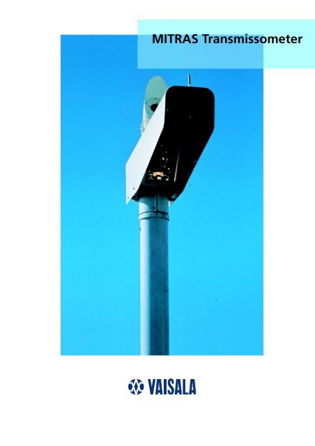
<strong>MITRAS</strong> Transmissometer
Reliable RVR with<br />
<strong>MITRAS</strong> Transmissometer<br />
Accurate RVR measurement reduces airport downtime<br />
and improves safety and reliability of<br />
operations.<br />
The <strong>MITRAS</strong> Transmissometer system provides You<br />
with correct visibility data without breaks.<br />
Vaisala’s <strong>MITRAS</strong> is a wellproven<br />
solution to Runway<br />
Visual Range assessment. The<br />
system has been <strong>in</strong> operational<br />
use s<strong>in</strong>ce 1986 and has demonstrated<br />
excellent performance <strong>in</strong><br />
<strong>in</strong>ternational <strong>in</strong>tercomparisons.<br />
<strong>MITRAS</strong> provides many operational<br />
and reliability benefits:<br />
• Conformance to all ICAO and<br />
WMO requirements for RVR and<br />
Meteorological Optical Range<br />
(MOR)<br />
• Fully automatic operation with<br />
excellent accuracy and stability<br />
• Unique contam<strong>in</strong>ation detection<br />
and compensation<br />
• Double basel<strong>in</strong>e for CAT IIIB<br />
by means of two different beams<br />
from one transmitter<br />
• Extensive built-<strong>in</strong> monitor<strong>in</strong>g<br />
to verify performance and to<br />
generate warn<strong>in</strong>gs before<br />
failures actually occur<br />
• Verified operation <strong>in</strong> all<br />
weather conditions<br />
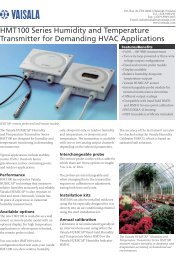
SYSTEM STRUCTURE<br />
The standard <strong>MITRAS</strong> Transmissometer<br />
consists of a light<br />
transmitter and a light receiver<br />
<strong>in</strong>stalled at a suitable distance<br />
from each other. <strong>MITRAS</strong> measures<br />
transmission of white light<br />
over the basel<strong>in</strong>e path and converts<br />
the measurement value to<br />
the correspond<strong>in</strong>g MOR value.<br />
The transmittance measurement<br />
resolution of <strong>MITRAS</strong> is better<br />
than 0.1 % and the measurement<br />
accuracy is better than 1 %.<br />
A s<strong>in</strong>gle basel<strong>in</strong>e <strong>MITRAS</strong> can be<br />
easily and economically upgraded<br />
to a double basel<strong>in</strong>e<br />
system when extended measurement<br />
range is needed for CAT<br />
IIIB applications. The two basel<strong>in</strong>es<br />
are realized by add<strong>in</strong>g an<br />
<strong>in</strong>dividual lens system <strong>in</strong> the<br />
transmitter unit and a second<br />
receiver unit. Excellent accuracy<br />
is guaranteed because the two<br />
separate light beams from the<br />
s<strong>in</strong>gle transmitter unit do not<br />
<strong>in</strong>terfere with each other.<br />
Vaisala’s LM11 Background<br />
Lum<strong>in</strong>ance Meter can be connected<br />
to a <strong>MITRAS</strong> transmitter<br />
unit. The lum<strong>in</strong>ance sensor is<br />
<strong>in</strong>terfaced to the <strong>MITRAS</strong> processor<br />
unit and it shares the<br />
same communication l<strong>in</strong>e with<br />
the transmissometer.<br />
<strong>MITRAS</strong> communicates the<br />
measurement results to a host<br />
system via a modem l<strong>in</strong>e. RVR<br />
calculations are carried out by a<br />
dedicated RVR computer or an<br />
<strong>in</strong>tegrated airport weather<br />
observation system and the<br />
results are sent to various<br />
displays.<br />
COST SAVINGS THROUGH<br />
EASY MAINTENANCE<br />
Contam<strong>in</strong>ation of the optical<br />
w<strong>in</strong>dows with time is <strong>in</strong>evitable<br />
and it can have a significant<br />
impact on RVR accuracy. MIT-<br />
RAS measures the w<strong>in</strong>dow contam<strong>in</strong>ation<br />
and automatically<br />
compensates for the loss <strong>in</strong><br />
measured transmittance. When<br />
The visibility measurement ranges achieved<br />
by s<strong>in</strong>gle and double basel<strong>in</strong>e <strong>MITRAS</strong><br />
systems are shown below. The basel<strong>in</strong>e of<br />
<strong>MITRAS</strong> can be freely selected between<br />
10 ... 200 m.<br />
Basel<strong>in</strong>e MOR range RVR range*)<br />
35 m 25 ... 1500 m 100 ... 1500 m<br />
50 m 40 ... 2000 m 150 ... 2000 m<br />
75 m 50 ... 3000 m 200 ... 3000 m<br />
100 m 70 ... 5000 m 300 ... 5000 m<br />
200 m 150 ... 10 000 m 500 ... 10 000 m<br />
*) The actual RVR range is dependent on runway light<strong>in</strong>g.<br />
The values shown are based on usual light<strong>in</strong>g arrangements.<br />
Basel<strong>in</strong>e MOR range RVR range*)<br />
10 and 75 m 7 ... 3000 m 40 ... 3000 m<br />
10 and 200 m 7 ... 10 000 m 40 ... 10 000 m<br />
(Double basel<strong>in</strong>e is required <strong>in</strong> CAT IIIB operat<strong>in</strong>g category.)
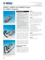
One background lum<strong>in</strong>ance meter, mounted<br />
on top of the light transmitter, is sufficient per<br />
runway to measure the background lum<strong>in</strong>ance<br />
value needed <strong>in</strong> visibility calculation.<br />
w<strong>in</strong>dow contam<strong>in</strong>ation exceeds<br />
an acceptable level, a warn<strong>in</strong>g is<br />
sent out and the w<strong>in</strong>dow can be<br />
cleaned. This unique function<br />
extends the clean<strong>in</strong>g <strong>in</strong>tervals<br />
significantly, while the user is<br />
assured of consistently high data<br />
quality.<br />
Each <strong>MITRAS</strong> unit cont<strong>in</strong>uously<br />
monitors several technical parameters<br />
and generates warn<strong>in</strong>g<br />
and alarm messages <strong>in</strong> cases of<br />
fault. The <strong>MITRAS</strong> status can be<br />
monitored remotely over the<br />
modem l<strong>in</strong>e. Automatic monitor<strong>in</strong>g<br />
<strong>in</strong> the transmitter and receiver<br />
covers supply voltages,<br />
<strong>in</strong>ternal temperatures, optical<br />
performance <strong>in</strong>clud<strong>in</strong>g correct<br />
calibration/alignment and detected<br />
failures. This <strong>in</strong>formation can<br />
be <strong>in</strong>terrogated by the service<br />
technician before leav<strong>in</strong>g for the<br />
site. Warn<strong>in</strong>gs of lamp age<strong>in</strong>g<br />
and w<strong>in</strong>dow contam<strong>in</strong>ation are<br />
generated as needed.<br />
The xenon flash lamp’s nom<strong>in</strong>al<br />
lifetime is 8 years at one flash<br />
per second. <strong>MITRAS</strong> extends the<br />
lifetime by adjust<strong>in</strong>g the flash<br />
rate depend<strong>in</strong>g on visibility. An<br />
<strong>in</strong>terval of one second between<br />
flashes is used <strong>in</strong> low visibility.<br />
The flash <strong>in</strong>terval <strong>in</strong>creases stepwise<br />
to 10 seconds when visibility<br />
improves to a measured value<br />
above 10 km.<br />
SUPERIOR ACCURACY<br />
In the WMO <strong>in</strong>tercomparison of<br />
visibility measurements, <strong>MITRAS</strong><br />
achieved the best results concern<strong>in</strong>g<br />
measurement accuracy.<br />
<strong>MITRAS</strong> measures both the transmitted<br />
and the received light<br />
pulse amplitudes. Instead of rely<strong>in</strong>g<br />
on estimates of projected<br />
light power, every transmitted<br />
pulse is measured. Atmospheric<br />
transmittance is then calculated<br />
as the ratio of received and<br />
transmitted light power on a<br />
s<strong>in</strong>gle pulse basis. Receiver electronics<br />
are gated to receive<br />
only light pulses from the transmitter,<br />
and will not accept any<br />
<strong>in</strong>terference light dur<strong>in</strong>g the<br />
<strong>in</strong>terval.<br />
The wide-bandwidth white light<br />
of the transmitter’s xenon flash<br />
lamp and the photopically<br />
corrected receiver sensitivity<br />
provide an ideal match of the<br />
human eye’s spectral range.<br />
<strong>MITRAS</strong> beams are optimized.<br />
Interference from other light<br />
sources, such as the sun or the<br />
aircraft lights is m<strong>in</strong>imized by<br />
accurate beam form<strong>in</strong>g. Light<br />
distribution across the beam is<br />
even. Multiple forward scatter<strong>in</strong>g<br />
and dispersion <strong>in</strong> fog is m<strong>in</strong>imized.<br />
Simplicity of optical design<br />
and good temperature stability<br />
are key factors of the system’s<br />
exceptional stability.<br />
Temperature of the optics is<br />
ma<strong>in</strong>ta<strong>in</strong>ed constant and above<br />
the ambient to prevent condensed<br />
moisture on the optical<br />
surfaces. Control is proportional<br />
to avoid temperature cycl<strong>in</strong>g.
Technical Information<br />
GENERAL<br />
Measur<strong>in</strong>g range<br />
0 ... 100 % transmittance<br />
Resolution<br />
0.02 % of transmittance<br />
Accuracy (verified by calibrated optical filters) 1 % of FSR<br />
Meets ICAO (Annex 3) recommendations <strong>in</strong> specific ranges.<br />
Time constant<br />
60 s<br />
Sample <strong>in</strong>terval<br />
1 s<br />
Basel<strong>in</strong>e allocations 10 ... 200 m altered by neutral density filters<br />
Height with standard pedestal (others on request) 2500 mm<br />
Calibration and checks<br />
With optical filters &<br />
ma<strong>in</strong>tenance term<strong>in</strong>al command checks<br />
Operat<strong>in</strong>g temperature –40 ... +55 °C<br />
Operat<strong>in</strong>g humidity<br />
0 ... 10 % RH<br />
W<strong>in</strong>d speed<br />
Construction withstands up to 60 m/s<br />
Power supply<br />
115/130/230/240 VAC<br />
+10 % -15 % of nom<strong>in</strong>al value 45.65 Hz,<br />
s<strong>in</strong>gle phase<br />
Weight<br />
35 kg<br />
Dimensions<br />
Optical head with hood<br />
390(h) × 225(w) × 980(l) mm<br />
Electron. box without rad. shield 310(h) × 400(w) × 190(l) mm<br />
Colour<br />
White<br />
Hous<strong>in</strong>g<br />
Alum<strong>in</strong>um, weatherproof<br />
Mount<strong>in</strong>g<br />
On concrete foundation<br />
LP11 LIGHT TRANSMITTER<br />
Light source<br />
Xenon flash bulb<br />
Peak radiated power (adjustable by commands) 40 ... 160 kW<br />
Lamp life<br />
55 000 hours<br />
Spectral output range<br />
300 .... 1100 nm<br />
Microprocessor<br />
8031 with application program<br />
to control all functions, calculations,<br />
communications and built-<strong>in</strong> test facilities<br />
Power consumption<br />
250 W/300 W with LM11<br />
MTBF (MIL-STD-217E)<br />
> 13 700 hours<br />
RVR computer <strong>in</strong>terface Modem CCITT V.21<br />
Dedicated l<strong>in</strong>e to RVR computer<br />
Without modem: RS-232C <strong>in</strong>terface<br />
Ma<strong>in</strong>tenance term<strong>in</strong>al <strong>in</strong>terface<br />
RS-232C, 300 baud<br />
Output message<br />
Visibility, transmittance values,<br />
lum<strong>in</strong>ance data (if connected),<br />
status data <strong>in</strong> ASCII<br />
Options<br />
Double basel<strong>in</strong>e optics (LPO11)<br />
LM11 Background Lum<strong>in</strong>ance Meter<br />
LR11 LIGHT RECEIVER<br />
Reception angle<br />
9 mrad<br />
Immunity to external light<br />
75 000 W halogen lamp<br />
30 m far (cont. light) has no <strong>in</strong>fluence<br />
Spectral response range<br />
300 ... 700 nm<br />
Peak wavelength<br />
550 nm<br />
Microprocessor<br />
8031 with application program<br />
to control all functions, calculations,<br />
communications and built-<strong>in</strong> test facilities<br />
Power consumption<br />
250 W<br />
Ma<strong>in</strong>tenance term<strong>in</strong>al <strong>in</strong>terface<br />
RS-232C, 300 baud<br />
MTBF (MIL-STD-217E)<br />
22 100 hours<br />
LM11 BACKGROUND LUMINANCE METER<br />
Measur<strong>in</strong>g range 4 ... 30 000 cd/m 2<br />
Accuracy 10 %<br />
Spectral response range<br />
300 ... 700 nm<br />
Peak wavelength<br />
550 nm<br />
Field of view<br />
5 degrees<br />
MTBF (MIL-STD-217E)<br />
183 000 hours<br />
Connection<br />
To any LP11 Light Transmitter<br />
Mount<strong>in</strong>g<br />
On top of LP11 by a screw<br />
Head Office:<br />
VAISALA Oy<br />
PL 26, FIN-00421 Hels<strong>in</strong>ki<br />
FINLAND<br />
Phone (<strong>in</strong>t.): (+358 0) 894 91<br />
Telefax: (+358 0) 894 9227<br />
Telex: 122832 vsala fi<br />
VAISALA GmbH<br />
Postfach 540267<br />
D-22502 Hamburg<br />
DEUTSCHLAND<br />
Phone (nat.): (040) 858 027<br />
Telefax: (040) 850 8444<br />
VAISALA (UK) Ltd<br />
Cambridge Science Park<br />
Milton Road<br />
Cambridge CB4 4GH<br />
UNITED KINGDOM<br />
Phone (nat.): (01223) 420 112<br />
Telefax: (01223) 420 988<br />
VAISALA TMI Ltd<br />
Vaisala House<br />
349 Bristol Road<br />
Birm<strong>in</strong>gham B5 7SW<br />
UNITED KINGDOM<br />
Phone (nat.): (0121) 683 1200<br />
Telefax: (0121) 683 1299<br />
VAISALA SA<br />
3, Parc Ariane<br />
Sa<strong>in</strong>t-Quent<strong>in</strong>-En-Yvel<strong>in</strong>es<br />
F-78284 Guyancourt Cedex<br />
FRANCE<br />
Phone (nat.): (1) 3057 2728<br />
Telefax: (1) 3096 0858<br />
VAISALA Inc.<br />
100 Commerce Way<br />
Woburn, MA 01801 - 1068<br />
USA<br />
Phone (nat.): (617) 933 4500<br />
Telefax: (617) 933 8029<br />
VAISALA KK<br />
42 Kagurazaka 6-Chome<br />
Sh<strong>in</strong>juku-Ku,<br />
Tokyo 162<br />
JAPAN<br />
Phone (nat.): (03) 3266 9611<br />
Telefax: (03) 3266 9610<br />
VAISALA Pty. Ltd.<br />
A.C.N. 006 500 616<br />
80 Dodds Street<br />
South Melbourne, VIC 3205<br />
AUSTRALIA<br />
Phone (nat.): (3) 9696 5699<br />
Telefax: (3) 9696 5776<br />
VAISALA Beij<strong>in</strong>g<br />
Representative Office<br />
Room 518, 520<br />
Wangfuj<strong>in</strong>g Grand Hotel<br />
No. 57 Wangfuj<strong>in</strong>g Street<br />
Beij<strong>in</strong>g 100006<br />
PEOPLE'S REPUBLIC OF CHINA<br />
Phone (nat.): (10) 522 4050<br />
Telefax: (10) 522 4051<br />
Ref. A591en 1995-11