How to set up 50cc.pdf - Precision Aerobatics
How to set up 50cc.pdf - Precision Aerobatics
How to set up 50cc.pdf - Precision Aerobatics

Create successful ePaper yourself
Turn your PDF publications into a flip-book with our unique Google optimized e-Paper software.
Despite all the positives there about this class,<br />
and the many models available in it, there are a<br />
co<strong>up</strong>le of hidden dangers that really need <strong>to</strong> be<br />
highlighted especially <strong>to</strong> those with little or no<br />
experience in selecting or <strong>set</strong>ting <strong>up</strong> a “giant<br />
scale gasser”, as the yanks would have you say.<br />
So I went and approached <strong>Precision</strong> <strong>Aerobatics</strong><br />
who were keen <strong>to</strong> sponsor this article and help <strong>to</strong><br />
shed some light on some of the mysteries that<br />
perplex many new modellers, not <strong>to</strong> mention<br />
showing off some of their classy hardware <strong>to</strong> anyone<br />
who want <strong>to</strong> <strong>set</strong> <strong>up</strong> such a craft. There is an<br />
important reason for this article and that is simply<br />
that many, if not most modern ARF in the 80+<br />
inch (2 metres +) come with either no hardware<br />
(which in my opinion is far better than the next)<br />
or with unsuitable hardware.<br />
The fact is that this class of plane means risk<br />
and responsibility go <strong>up</strong>….in fact way <strong>up</strong>, so<br />
each builder and flier must recognize that and<br />
take precautions accordingly. I have had a co<strong>up</strong>le<br />
of <strong>50cc</strong> planes that were bought as ARF’s and<br />
the hardware was terrible, and in one case,<br />
(because I used it as it came out of the box) it<br />
lead <strong>to</strong> the very early demise of an<br />
otherwise great model. In the case<br />
of the other model I lost one aileron<br />
and one eleva<strong>to</strong>r on the third flight<br />
because the s<strong>up</strong>plied CA hinges<br />
(that’s right, CA hinges on a <strong>50cc</strong><br />
model…deadly) gave way. I managed<br />
<strong>to</strong> land that one but those<br />
hinges were swapped over for<br />
Robarts very soon after.<br />
Fortunately some manufacturers,<br />
like <strong>Precision</strong> <strong>Aerobatics</strong>, have<br />
raised the bar enormously, but sadly<br />
there are still more and more coming<br />
<strong>to</strong> our shores that just do not<br />
make the grade. I recently looked at<br />
a co<strong>up</strong>le of ARF’s on behalf of an<br />
interested friend that were nothing<br />
short of scary…..really, really scary.<br />
Don’t forget, in this industry, there<br />
are no defined operating ISO standards<br />
<strong>to</strong> meet. That means it’s <strong>up</strong> <strong>to</strong><br />
you, the builder and flier, <strong>to</strong> judge<br />
the suitability of the airframe and<br />
hardware, rather than assume that<br />
what is s<strong>up</strong>plied by our good friends in (generally)<br />
Asia is adequate.<br />
Hence therefore….this parts review is intended<br />
<strong>to</strong> show newcomers how <strong>to</strong> <strong>set</strong> <strong>up</strong> a large<br />
model and what <strong>to</strong> use <strong>to</strong> do it. We will be <strong>set</strong>ting<br />
<strong>up</strong> my beloved 1/3 scale Pitts Special (after<br />
a major remodel) using some saucy PA hardware<br />
and occasionally I will refer <strong>to</strong> my 84” <strong>Precision</strong><br />
<strong>Aerobatics</strong> Edge 540T as reference.<br />
Let’s Go Shopping!<br />
This may be a little different for many modellers<br />
who have been used <strong>to</strong> scavenging gear<br />
out of old draws, pulling servos from old planes,<br />
and a battery pack out from behind all the other<br />
bits in the c<strong>up</strong>board. While gear that has survived<br />
the demise of another giant plane may well<br />
be reusable, you generally need <strong>to</strong> select gear<br />
that’s tailored <strong>to</strong> the requirements of the <strong>set</strong><strong>up</strong><br />
you are after. There is plenty of assistance out<br />
there and the guys at PA are always willing <strong>to</strong><br />
help you out as they have plenty of knowledge<br />
and experience. Either way, the main point here<br />
is select wisely and don’t take shortcuts with the<br />
equipment. You will find that on any really serious<br />
<strong>50cc</strong> aerobatic plane there is nothing in there<br />
that is not essential…(you try flying a plane with<br />
a 2.5:1 power <strong>to</strong> weight ratio at full tit ‘till it runs<br />
out of fuel because that dodgy throttle servo<br />
fizzed and locked <strong>up</strong> on you!)<br />
The same as above applies <strong>to</strong> all your connections,<br />
linkages and so forth. That being said,<br />
I will do my best throughout this series <strong>to</strong> highlight<br />
the equipment and hardware in this particular<br />
<strong>set</strong> <strong>up</strong> and the reasons for doing so.<br />
The Engine<br />
This provides the heart throb <strong>to</strong> your beast.<br />
The Pitts is going <strong>to</strong> sport my trusty DA50. There<br />
are actually very few similarities when <strong>set</strong>ting <strong>up</strong><br />
gas (read petrol) as apposed <strong>to</strong> glow engines,<br />
overall though it’s not really any more complicated.<br />
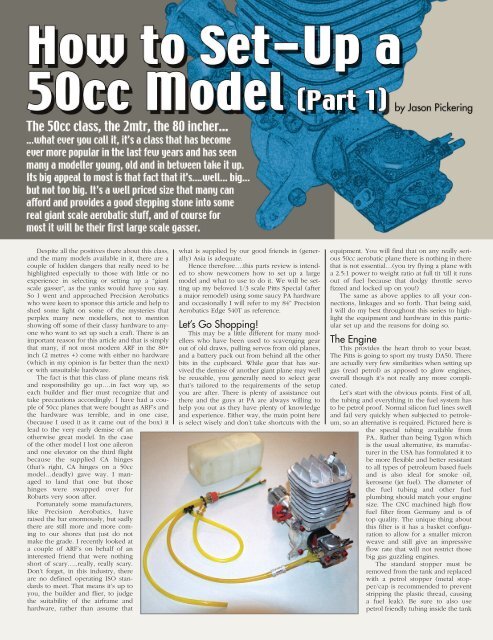
Let’s start with the obvious points. First of all,<br />
the tubing and everything in the fuel system has<br />
<strong>to</strong> be petrol proof. Normal silicon fuel lines swell<br />
and fail very quickly when subjected <strong>to</strong> petroleum,<br />
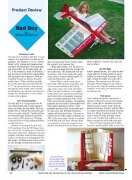
so an alternative is required. Pictured here is<br />
the special tubing available from<br />
PA.. Rather than being Tygon which<br />
is the usual alternative, its manufacturer<br />
in the USA has formulated it <strong>to</strong><br />
be more flexible and better resistant<br />
<strong>to</strong> all types of petroleum based fuels<br />
and is also ideal for smoke oil,<br />
kerosene (jet fuel). The diameter of<br />
the fuel tubing and other fuel<br />
plumbing should match your engine<br />
size. The CNC machined high flow<br />
fuel filter from Germany and is of<br />
<strong>to</strong>p quality. The unique thing about<br />
this filter is it has a basket configuration<br />
<strong>to</strong> allow for a smaller micron<br />
weave and still give an impressive<br />
flow rate that will not restrict those<br />
big gas guzzling engines.<br />
The standard s<strong>to</strong>pper must be<br />
removed from the tank and replaced<br />
with a petrol s<strong>to</strong>pper (metal s<strong>to</strong>pper/cap<br />
is recommended <strong>to</strong> prevent<br />
stripping the plastic thread, causing<br />
a fuel leak). Be sure <strong>to</strong> also use<br />
petrol friendly tubing inside the tank
<strong>to</strong> the clunk as I have seen this missed by some<br />
in the past. You will also note that only two exits<br />
are required out of the tank as the filler line is<br />
run directly off the main feed <strong>to</strong> the carby via a<br />
plastic tee. The fuel dots are also available in various<br />
styles and sizes depending on the size tubing<br />
and your taste. It is also recommended that<br />
you solder a fuel barb <strong>to</strong> each brass tube of the<br />
fuel tank and again use a small zip tie <strong>to</strong> prevent<br />
the tubes from slipping off.<br />
The other outlet is for a vent. This is best exited<br />
out the bot<strong>to</strong>m of the fuselage and run <strong>to</strong><br />
behind the tank (<strong>to</strong> prevent fuel dribbling out<br />
when the plane is nose down) or looped behind<br />
the tank and back <strong>to</strong> the cowl if you prefer the<br />
exit <strong>up</strong> front. Zip ties are used <strong>to</strong> secure the connections<br />
and a leak test is a good idea. This can<br />
be performed out side the aircraft by filling it,<br />
blocking the hose ends and continue filling. Not<br />
a lot of pressure is required but check for weeping<br />
and rectify if needed.<br />
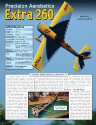
The next obvious change is the ignition.<br />
There are no real mysteries here, its really all just<br />
common sense. A separate power s<strong>up</strong>ply is<br />
needed, and you don’t have <strong>to</strong> go overboard<br />
with the size of battery pack. The one pictured is<br />
only 800mAh and I have found that <strong>to</strong> be adequate<br />
although I definitely wouldn’t go any<br />
smaller. Having said that, something in the range<br />
of 2300mAh is more often recommended, so<br />
choose according <strong>to</strong> your consumption rate. A<br />
good quality high current switch is needed as the<br />
vibration can cause a standard one <strong>to</strong> fail. The<br />
beauty with these particular ones pictured is that<br />
the back can be easily flicked off and the wires<br />
s<strong>up</strong>plied with the engine can be soldered on as<br />
seen in the pho<strong>to</strong>. You will also note that there<br />
is a non standard plastic sheath slipped over the<br />
wire braiding on the plug lead. I always do this<br />
as a precaution <strong>to</strong> protect the braid as the wire<br />
lead will emit some serious radio noise if the<br />
braiding is damaged. Plastic sheathing is available<br />
from Dick Smith Electronics or similar s<strong>to</strong>res<br />
as well as au<strong>to</strong> electrical s<strong>up</strong>pliers.<br />
Well that’s really it for the hook-<strong>up</strong>, now for<br />
the <strong>set</strong> <strong>up</strong> in the Pitts. Again things are a little different<br />
here. The tank for instance, can be placed<br />
virtually anywhere and as far away from the carb<br />
as desired. This is on account of the petrol carburet<strong>to</strong>r<br />
having its own pump <strong>to</strong> drag the fuel<br />
through. Obviously the best place then <strong>to</strong> put it<br />
is as close <strong>to</strong> the centre of gravity as possible,<br />
although in this case I’ll put it in its original place<br />
for convenience.0<br />
The stand offs are bolted <strong>to</strong> the firewall and<br />
Loctite is used on all bolts. The ignition module<br />
is cable tied <strong>to</strong> the engine box with foam under<br />
it and the switch and battery pack installed. The<br />
important thing <strong>to</strong> remember is <strong>to</strong> try <strong>to</strong> keep as<br />
much separation as possible between anything<br />
associated with the ignition, and anything associated<br />
with the receiver & radio gear including<br />
leads <strong>to</strong> prevent any chance of interference.<br />
The easiest way <strong>to</strong> accomplish this is <strong>to</strong> have<br />
engine gear <strong>up</strong> front, radio gear down back. Size<br />
wise the allocation of space is usually not a problem,<br />
but of course the CG placement is important<br />
<strong>to</strong>o. I usually find it best once the mo<strong>to</strong>r is bolted<br />
on <strong>to</strong> sit the major components loosely in the<br />
model and move them around until the best CG<br />
is accomplished, so I then have an idea where it’s<br />
all going <strong>to</strong> go. Either way, try <strong>to</strong> push all the<br />
ignition gear as far <strong>up</strong> the front as possible <strong>to</strong><br />
keep it a safe distance from the radio.<br />
Propellers<br />
<strong>Precision</strong> <strong>Aerobatics</strong> did a fair bit of research<br />
in this area before selecting the brands they sell.<br />
I’ve used both the JXF and PT Carbons and both<br />
have not only exceeded the performance of any<br />
others I’ve used, but have also been either similarly<br />
or better priced than their well known counterparts.<br />
The PT has given better thrust than my<br />
Mejzlik of the same size & is significantly lighter<br />
and quieter. JXF wooden prop in my opinion<br />
leaves any other wooden I have used for dead.<br />
With larger wooden props there can be a tendency<br />
<strong>to</strong> twist out in the pitch at high RPM. This of<br />
course affects the efficiency, so steer clear of any<br />
props that twist easily. The JXF has good resistance<br />
<strong>to</strong> this and comes in a highly glossed finish.<br />
The advantage of the wooden props over the<br />
carbon fibre props lies in its light weigh. This<br />
advantage goes beyond the obvious wing loading;<br />
it also allows the engine <strong>to</strong> spool <strong>up</strong> quickly<br />
therefore giving fast thrust response when doing<br />
3D manoeuvres. The Pitts will be fitted with the<br />
JXF as it is of course cheaper than the carbon<br />
fibre option. As far as prop sizing goes, there are<br />
many variables depending on the engine you are<br />
using, so consult your manual. <strong>How</strong>ever as a<br />
generic guide, generally for break in you would<br />
want <strong>to</strong> go one size smaller (for the DA 50- 22 x<br />
8) <strong>to</strong> prevent over loading the engine, then for<br />
3D you want big diameter with a fine pitch (23 x<br />
8). This gives you good thrust but a lower <strong>to</strong>p<br />
end speed and gives you good speed control in<br />
the down lines. If you were after more sport performance<br />
you’d go for something like a 22 x 10<br />
or even 22 x 12 for speed.<br />
When looking at the pitch of a larger prop, do<br />
not be deceived by the ‘flat’ appearance of it.<br />
Remember, the pitch is in direct relation <strong>to</strong> the<br />
diameter. That is if the pitch is 8” then the propeller<br />
would in theory ‘screw forward’ 8” per revolution<br />
across the entire diameter. So for example<br />
the extremity of a 23” propeller has <strong>to</strong> complete a<br />
circumference of 72+” <strong>to</strong> ‘screw forward’ 8”.<br />
Therefore its ‘incidence’ at that point will not be<br />
very great, yet will still be very effective.<br />
The most important thing when it comes <strong>to</strong><br />
fitting a big prop is the balancing. Use a good<br />
balancer and balance both the blades and the<br />
hub. Do this by first sitting the prop horizontal in<br />
the balancer, and if one side drops, counter balance<br />
the other end with some clear enamel. As it<br />
dries it will lighten, so a bit of a guess is<br />
involved, but it only takes a few minutes <strong>to</strong> dry<br />
so, it can be adjusted ‘till it is correct.<br />
Balancing the prop is imperative. If you don’t<br />
have a balancer; buy one, borrow one, or build<br />
one. Even if a prop is “fac<strong>to</strong>ry balanced”, as are<br />
the PT props, I always check them anyway<br />
(although I am yet <strong>to</strong> find one that’s out). In any<br />
case it gives good piece of mind <strong>to</strong> know for sure<br />
that they are right. A good balanced propeller will<br />
be balanced in any position on the balancer.
Spinners<br />
Here is an opportunity <strong>to</strong> add some serious<br />
good looks <strong>to</strong> your model. <strong>Precision</strong> <strong>Aerobatics</strong><br />
has a few cool options here both in shape and<br />
material. With sizes ranging from 80mm <strong>up</strong> <strong>to</strong><br />
152mm (and even a new 38mm for electric powered<br />
models!) and a choice of the curvaceous<br />
standard shape or the sharper Ultimate, there’s<br />
something <strong>to</strong> suit everybody. Add <strong>to</strong> that the<br />
options of…yep you got it…Carbon Fibre or this<br />
really funky aluminium coated glass. Both mount<br />
<strong>to</strong> a lightened CNC machined alloy backing plate.<br />
The aluminized glass is the perfect choice for<br />
those who want the look of a silver metal spinner<br />
but don’t want <strong>to</strong> pay the enormous weight<br />
penalty of an alloy one. Even on a giant you don’t<br />
want <strong>to</strong> have dead weight, especially if you are<br />
trying <strong>to</strong> achieve high performance.<br />
On the PA Edge 540T, I have used a Carbon<br />
fibre spinner in the standard shape. The Pitts will<br />
sport a 4” ‘aluminized glass’ spinner. Both are<br />
extremely light, perfectly balanced and seriously<br />
sweet <strong>to</strong> look at. The lightness of the cone almost<br />
eliminates the possibility of balancing issues and<br />
they are much easier <strong>to</strong> cut than aluminium.<br />
To fit, first drill out the backing plate, making<br />
sure that the prop is positioned in a way not <strong>to</strong><br />
interfere with the attachment tabs for the cone.<br />
Then fit the backing plate along with the prop<br />
and prop plate <strong>to</strong> the mo<strong>to</strong>r. Once that is fitted,<br />
cut a template of the prop blade where it will<br />
exit the cone, allowing enough clearance <strong>to</strong><br />
avoid <strong>to</strong>uching. Use the template <strong>to</strong> mark the<br />
cone on both sides; then check that the alignment<br />
is ok before cutting.<br />
I use a Dremel with a small abrasive blade <strong>to</strong><br />
do the rough cut and then use a small sanding<br />
drum <strong>to</strong> trim it out. A co<strong>up</strong>le of trial fits may be<br />
needed <strong>to</strong> get that right, especially making sure<br />
there is no contact with the prop. The main thing<br />
I like about these spinners apart from the ‘bling’<br />
fac<strong>to</strong>r (which is a biggy) is the way the cone is<br />
attached <strong>to</strong> the backing plate. Rather that a single<br />
bolt through the centre which can allow the<br />
cone <strong>to</strong> rotate, they use but<strong>to</strong>n head screws<br />
around the circumference. These screws fasten <strong>to</strong><br />
small tabs on the backing plate and secure the<br />
cone very nicely. They also eliminate the need <strong>to</strong><br />
machine a centre bolt as is often needed with an<br />
alloy spinner.<br />
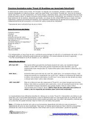
Undercarriage<br />
Of course we would assume your aircraft has<br />
legs, and wheels are easily come by. <strong>How</strong>ever;<br />
swank looking wheel pants are not so easily<br />
found….that is until now. These fella’s are the<br />
nicest I have seen; nicely shaped, well priced<br />
and well made. Of course following in the tradition<br />
of everything else that comes out of the PA<br />
fac<strong>to</strong>ry; they are s<strong>up</strong>er light. The sizes are <strong>to</strong> suit<br />
.40-.60 size, 27% size and 35%. Of course, they<br />
are available in Fibreglass or Carbon Fibre, both<br />
weighing roughly the same, but CF definitely<br />
being stronger.<br />
They can of course be fitted in the usual fashion,<br />
but due <strong>to</strong> the irregular runway at my club<br />
being no<strong>to</strong>rious for busting spats, I always fit<br />
mine a little differently. I start by gluing small ply<br />
blocks <strong>to</strong> both sides (on the inside of course) of<br />
the spat with epoxy. Once dry, I then drill right<br />
through the spat and out the other side for the<br />
axle. I use a 5mm cap screw (these generally are<br />
hardened <strong>to</strong> 12.6 off the shelf) for this and run it<br />
all the way through the spat (refer <strong>to</strong> Diagram).<br />
The wheel is centred with wheel collars and two<br />
nuts clamping the spat and leg <strong>to</strong>gether. I then<br />
use a small screw through the leg and right in<strong>to</strong><br />
the ply block <strong>to</strong> prevent rotation of the spat.<br />
Some would prefer not <strong>to</strong> see the cap, but I<br />
have never seen a full-size spat without a bolt<br />
through here anyway, so I figure it’s a scale look<br />
as well as being practical. With the extra s<strong>up</strong>port<br />
on the outside of the spat it helps <strong>to</strong> hold it rigid<br />
and s<strong>up</strong>ports it when it’s bumped or knocked. Of<br />
course if you’re a more conventional type of guy,<br />
there’s nothing s<strong>to</strong>pping you mounting them in<br />
your own way.<br />
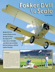
Tail Wheel<br />
Again Carbon Fibre features here <strong>to</strong>o. The one<br />
pictured is designed specifically <strong>50cc</strong> sized<br />
planes; it is extremely light and very <strong>to</strong>ugh. I<br />
have found that many tail wheels that are s<strong>up</strong>plied<br />
in this category don’t ‘cut the mustard’.<br />
Have a good look at the one s<strong>up</strong>plied with your<br />
model (if there is one) and be sure you are satisfied.<br />
If not, this one is a great alternative. There<br />
are no real mysteries as <strong>to</strong> how <strong>to</strong> fit it; the carbon<br />
arm is screwed <strong>to</strong> the fuselage in the usual<br />
fashion and the springs are stretched <strong>up</strong> <strong>to</strong> the<br />
arm on the rudder. There is no need <strong>to</strong> put <strong>to</strong>o<br />
much tension on the springs, nor is there any real<br />
need <strong>to</strong> go over board with twisting the ends on<br />
the steering arms; just a simple bend is required<br />
as can be seen in the pho<strong>to</strong>. I usually start off<br />
with a bit of extra tension on the springs, then<br />
check <strong>to</strong> see how well the tail wheel tracks with<br />
the rudder and ‘stretch’ the springs <strong>to</strong> suit.<br />
<strong>Precision</strong> <strong>Aerobatics</strong> also offers a Kevlar version<br />
of this tail wheel (painted white) which is softer<br />
in the ‘bounce’ as Kevlar is more flexible.<br />
These composites, particularly Carbon, offer<br />
more rigidity for much less weight than alloy and<br />
as you know…weight is everything. <strong>Precision</strong><br />
<strong>Aerobatics</strong> is currently developing a range of<br />
main gear out of carbon also.<br />
Conclusion<br />
Well that’s it for this issue. We’ve covered the<br />
basic hardware installation, enough <strong>to</strong> make your<br />
plane look like really trick. Next issue we will get<br />
in<strong>to</strong> the nitty gritty of power s<strong>up</strong>ply options, <strong>set</strong><br />
<strong>up</strong> of receivers, extension leads, servos, right<br />
through <strong>to</strong> the extension arms, linkages and control<br />
horns. This is the area where you may see<br />
most of the changes from smaller glow aircraft,<br />
and is the area that spawns most of the burning<br />
questions. Until then, happy building.