Expanding Gate Valve - Associated Valve
Expanding Gate Valve - Associated Valve
Expanding Gate Valve - Associated Valve

You also want an ePaper? Increase the reach of your titles
YUMPU automatically turns print PDFs into web optimized ePapers that Google loves.
<strong>Expanding</strong> <strong>Gate</strong> <strong>Valve</strong><br />
Technical Bulletin<br />
MJ-1761 August 2005
M&J <strong>Valve</strong><br />
19191 Hempstead Highway<br />
Houston, TX 77065<br />
Telephone: 281-469-0550<br />
Fax: 281-894-1332<br />
E-Mail: mandjvalve@processequipment.spx.com<br />
Web Site: www.mandjvalve.com<br />
SPX Process Equipment reserves the right to incorporate<br />
our latest design and material changes without notice or<br />
obligation. Design features, materials of construction and<br />
dimensional data, as described in this bulletin, are provided<br />
for your information only and should not be relied upon<br />
unless confirmed in writing. Certified drawings are available<br />
upon request.
Table of Contents<br />
<strong>Expanding</strong> <strong>Gate</strong> <strong>Valve</strong><br />
Design Types .............................................................................................................................................................. 3<br />
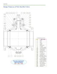
Design Features<br />
<strong>Valve</strong> Operation ................................................................................................................................................... 3<br />
Emergency Seat Seal .......................................................................................................................................... 4<br />
Stem Features ..................................................................................................................................................... 4<br />
Stem Sealing Features ........................................................................................................................................ 4<br />
Pressure Relief .................................................................................................................................................... 4<br />
Recommended Spare Parts ................................................................................................................................. 5<br />
Service ................................................................................................................................................................. 5<br />
Nameplate Data ................................................................................................................................................... 5<br />
Fire Test Qualifications ......................................................................................................................................... 5<br />
Standard Product/Options .................................................................................................................................... 5<br />
Warranty ............................................................................................................................................................ 12<br />
Trim Charts<br />
Exploded View ..................................................................................................................................................... 6<br />
Figure Number Key .............................................................................................................................................. 6<br />
Trims for Selected Services ................................................................................................................................. 6<br />
Trim Definitions .................................................................................................................................................... 7<br />
Seal Definitions .................................................................................................................................................... 7<br />
Drawings<br />
Assembly ............................................................................................................................................................ 2<br />
Outline Dimensions ........................................................................................................................................... 8,9<br />
Yoke Tube Flange Dimensions .......................................................................................................................... 11<br />
Engineering Data<br />
Operator Sizing .................................................................................................................................................. 10<br />
Weight Data ..................................................................................................................................................... 8,9<br />
Issued: August 2005 MJ-1761 3
<strong>Expanding</strong> <strong>Gate</strong> <strong>Valve</strong><br />
API 6D <strong>Expanding</strong> <strong>Gate</strong> <strong>Valve</strong>s<br />
The M&J Model EG valves are full bore through<br />
conduit valves with rising stem and parallel expanding<br />
gate and segment for tight mechanical seal and<br />
positive shut-off, both upstream and downstream, and<br />
under both low and high differential pressure. This<br />
design has proven performance in critical applications<br />
all over the world, such as isolation valves in power<br />
plants, ESD valves in production, block valves<br />
in process systems, high temperature valves in<br />
refineries, and pipeline valves in critical areas. The<br />
M&J Model EG is constructed for increased reliability<br />
and ease of maintenance and operation. These<br />
valves are readily available in all the sizes, pressure<br />
ranges, and trims used in piping systems requiring the<br />
positive shut off of liquid or gas.<br />
2” - 4”<br />
6” and Larger<br />
API 6A NON-RISING STEM EXPANDING GATE VALVES<br />
M&J also manufactures Model EG Non-Rising Stem <strong>Expanding</strong> <strong>Gate</strong> <strong>Valve</strong>s. These valves are manufactured and tested<br />
in accordance with API 6A and are available in 2000 and 3000 psi working pressures.<br />
4 MJ-1761 Issued: August 2005
<strong>Expanding</strong> <strong>Gate</strong> <strong>Valve</strong><br />
<strong>Valve</strong> Operation<br />
The valve’s parallel expanding gate and segment provides a tight mechanical<br />
seat seal upstream and downstream and under low and high differential<br />
pressure conditions.<br />
Open Position<br />
The <strong>Expanding</strong> <strong>Gate</strong> <strong>Valve</strong><br />
achieves its sealability by<br />
mechanically expanding the gate<br />
and segment assembly against the<br />
seats. The valve must be torqued<br />
fully open or fully closed to seal<br />
properly. Do NOT back off on the<br />
handwheel; leave it tight in both<br />
the open and closed positions.<br />
This method of operation prevents<br />
damage to the sealing surfaces of<br />
the gate and seat and isolates the<br />
body cavity preventing buildup of<br />
foreign material, increasing the life<br />
of the valve.<br />
1. Travelling to the final open position the lower back angles are in contact<br />
with each other. With further upward movement of the gate with the<br />
segment stopped, the centralizer mechanism allows the gate-segment<br />
assembly to expand, sealing against both seats, protecting the seat faces<br />
from line flow, while isolating the body cavity from the flow bore.<br />
2. During open and closing travel, the gate-segment assembly is collapsed<br />
with both back angle surfaces in contact. The centralizer mechanism<br />
prevents relative movement between the gate and segment allowing the<br />
gate and segment assembly to travel freely without sticking or wedging.<br />
Closed Position<br />
3. Travelling to the final closed position, the upper back angles of the gate<br />
and segment move into contact with each other. With further downward<br />
movement of the segment stopped, the centralizer mechanism allows the<br />
gate-segment assembly to expand, sealing against both seats, forming a<br />
tight mechanical seal.<br />
Issued: August 2005 MJ-1761 5
<strong>Expanding</strong> <strong>Gate</strong> <strong>Valve</strong><br />
Emergency Seat Seal<br />
The M&J <strong>Expanding</strong> <strong>Gate</strong> <strong>Valve</strong> requires no<br />
lubrication. If foreign matter causes damage to the<br />
seat seal during operation, all valves are fitted with<br />
an emergency sealant injection provision (Fig. 1).<br />
Sealant can be injected directly to the seat sealing<br />
area to effect an emergency seal. If valves are to be<br />
buried, or in an inaccessible location, these fittings<br />
can be extended per the customer’s requirements.<br />
Sealant<br />
Fitting<br />
Body<br />
Sealant Passage<br />
Stem Features<br />
The M&J <strong>Expanding</strong> <strong>Gate</strong> <strong>Valve</strong> is a one-piece stem<br />
design which has an integrally forged stem head.<br />
Stem<br />
Bonnet/yoke<br />
Top Adapter<br />
Pressure Rings<br />
Lantern Ring<br />
X-ring<br />
Pressure Rings<br />
Bottom<br />
Adapter<br />
Fig. 1<br />
<strong>Gate</strong><br />
Seat<br />
Insert<br />
Seat<br />
Fig. 2<br />
Stem Sealing Features<br />
The stem seal design (Fig. 2) utilizes Chevron rings<br />
to insure sealing integrity. The packing box seal<br />
configuration is an open/closed design to allow<br />
emergency bulk packing injection in the event of a<br />
stem leak. Alternate seal designs are available to meet<br />
a wide variety of customers requirements.<br />
Fig. 3a<br />
Relief<br />
<strong>Valve</strong><br />
Fig. 3b<br />
Check <strong>Valve</strong><br />
Needle <strong>Valve</strong>s<br />
Pressure Relief<br />
The M&J <strong>Expanding</strong> <strong>Gate</strong> <strong>Valve</strong> design<br />
will trap pressure in the valve body cavity<br />
when the valve is in the full open or<br />
closed position. High internal pressures<br />
can result from thermal expansion. To<br />
protect the valve from overpressure,<br />
the valve is provided with upstream<br />
relief piping which relieves excess body<br />
pressure to the upstream side of the<br />
valve (Fig. 3B). As an alternate, a relief<br />
valve can be provided (Fig. 3A).<br />
6 MJ-1761 Issued: August 2005
<strong>Expanding</strong> <strong>Gate</strong> <strong>Valve</strong><br />
Recommended Spare Parts<br />
It is recommended that the following spare parts be<br />
inventoried in operations having numerous valves of a given<br />
size and an in-house maintenance program:<br />
Number of valves to be supported<br />
Part Description<br />
<strong>Expanding</strong> <strong>Gate</strong> <strong>Valve</strong><br />
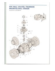
Exploded View<br />
Figure Number Key<br />
Standard Metallic Trims<br />
For Selected Services<br />
T1 - Standard - Carbon Steel -- Hydrocarbons<br />
T3 - Full Stainless Steel - Highly Corrosive<br />
T4 - Carbon Steel - NACE<br />
T6 - Carbon Steel - 410SS Internals - NACE<br />
T7 - Brine - Salt - Mildly Corrosive - NACE<br />
T8 - Waterflood - Brine - NACE<br />
S4 - Carbon Steel - NACE - 17-PH Stem<br />
G1 - High Temperature - Geothermal<br />
G2 - High Temperature - Geothermal - HF <strong>Gate</strong><br />
L1 - Low Temperature - Carbon Steel<br />
L4 - Low Temperature - NACE Carbon Steel<br />
ENP - Electroless Nickel Plated<br />
HF - Hard Faced<br />
Note: This is a sample of services and standard trims.<br />
For assistance with a specific service, contact your<br />
local M&J representative.<br />
8 MJ-1761 Issued: August 2005
<strong>Expanding</strong> <strong>Gate</strong> <strong>Valve</strong><br />
Trim Code Definitions<br />
Item Description T1 L1 T3 T4 L4 T6 T7 T8 S4 G1 G2<br />
ASTM A216 WCC/<br />
B1 Body ASTM A216 WCC ASTM A350 LCC ASTM A351 CF8M ASTM A216 WCC ASTM A350 LCC ASTM A216 WCC<br />
EPOXY COATED<br />
ASTM A216 WCC/<br />
ASTM A216 WCC ASTM A216 WCC ASTM A216 WCC<br />
EPOXY COATED<br />
ASTM A516 GR. 70/<br />
B2 Bonnet ASTM A516 GR. 70 ASTM A537 CL1 AISI 316SS ASTM A516 GR. 70 ASTM A537 CL1 ASTM A516 GR. 70<br />
EPOXY COATED<br />
ASTM A516 GR. 70/<br />
ASTM A516 GR. 70 ASTM A516 GR. 70 ASTM A516 GR. 70<br />
EPOXY COATED<br />
B3 Yoke Tube ASTM A516/A36/A53<br />
ASTM A537<br />
CL1/A333<br />
ASTM A516/A36/A53<br />
625 CLAD PKG BOX ASTM A516/A36/A53 ASTM A537<br />
CL1/A333<br />
ASTM A516/A36/A53 ASTM A516/A36/A53 ASTM A516/A36/A53 ASTM A516/A36/A53 ASTM A516/A36/A53 ASTM A516/A36/A53<br />
ASTM A216 GR.<br />
T1 <strong>Gate</strong> & Segment<br />
WCC/ENP<br />
ASTM A216 GR.<br />
ASTM A351 CF8M<br />
WCC/ENP<br />
ASTM A216 GR.<br />
WCC/ENP<br />
ASTM A216 GR.<br />
WCC/ENP<br />
ASTM A487 GR<br />
CA6NM<br />
ASTM A216 GR<br />
WCC/ENP<br />
ASTM A747 GR<br />
CB7CU-1 (17-4PH)<br />
ASTM A216 GR<br />
WCC/ENP<br />
ASTM A216<br />
GR WCC/ENP<br />
ASTM A216<br />
GR WCC/HF<br />
ASTM B630 17-4PH<br />
T2 Stem AISI 4140/ENP AISI 4140/ENP<br />
H1150<br />
AISI 4140/ENP AISI 4140/ENP AISI 410 AISI 4140/ENP<br />
ASTM B630 17-4PH<br />
H1150<br />
ASTM B630 17-4PH<br />
H1150<br />
ASTM B630 17-4PH<br />
H1150<br />
ASTM B630 17-4PH<br />
H1150<br />
ASTM 1018/<br />
T3 Seat Assembly AISI 1018/ENP/TFE AISI 1018/ENP/TFE AISI 316/HF/TFE AISI 1018/ENP/TFE AISI 1018/ENP/TFE AISI 410/NITRO H AISI 1018/ENP/TFE AISI 316/HF/TFE AISI 1018/ENP/TFE<br />
HF-40% GFTFE<br />
ASTM 1018/<br />
HF/40% GFTFE<br />
T4 <strong>Gate</strong> Skirt ASTM A36 ASTM A36 AISI 316SS ASTM A36 ASTM A36 AISI 410 ASTM A36/ENP ASTM A36/ENP ASTM A36 ASTM A36 ASTM A36<br />
T5 Segment Skirt ASTM A36 ASTM A36 AISI 316SS ASTM A36 ASTM A36 AISI 410 ASTM A36/ENP ASTM A36/ENP ASTM A36 ASTM A36 ASTM A36<br />
ASTM A193 B7<br />
A1 Body/Bonnet Studs ASTM A193 B7 ASTM A320 L7<br />
FLRCTD<br />
ASTM A193 B7M ASTM A320 L7M ASTM A193 B7 ASTM A193 B7M ASTM A193 B7M ASTM A193 B7M ASTM A193 B7M ASTM A193 B7M<br />
ASTM A194 2H<br />
A2 Body/Bonnet Nuts ASTM A194 2H ASTM A194 GR. 7<br />
FLRCTD<br />
ASTM A194 2HM ASTM A194 GR. 7M ASTM A194 2H ASTM A194 2HM ASTM A194 2HM ASTM A194 2HM ASTM A194 2HM ASTM A194 2HM<br />
ASTM A193 B7<br />
A3 Yoke Tube/Bonnet Studs ASTM A193 B7 ASTM A320 L7<br />
FLRCTD<br />
ASTM A193 B7M ASTM A320 L7M ASTM A193 B7 ASTM A193 B7M ASTM A193 B7M ASTM A193 B7M ASTM A193 B7M ASTM A193 B7M<br />
A4 Yoke Tube/Bonnet Nuts ASTM A194 2H ASTM A194 GR. 7<br />
ASTM A194 2H<br />
FLRCTD<br />
ASTM A194 2HM ASTM A194 GR. 7M ASTM A194 2H ASTM A194 2HM ASTM A194 2HM ASTM A194 2HM ASTM A194 2HM ASTM A194 2HM<br />
F1 Packing Fitting Steel 18-8 SST 18-8 SST 18-8 SST 18-8 SST 18-8 SST 18-8 SST 18-8 SST 18-8 SST 18-8 SST 18-8 SST<br />
F2 Packing Plug/Vent Steel 18-8 SST 18-8 SST 18-8 SST 18-8 SST 18-8 SST 18-8 SST 18-8 SST 18-8 SST 18-8 SST 18-8 SST<br />
F3 Body Vent/Grs Fitting Steel 18-8 SST 18-8 SST 18-8 SST 18-8 SST 18-8 SST 18-8 SST 18-8 SST 18-8 SST 18-8 SST 18-8 SST<br />
Seal Code Definitions<br />
Seal Definitions<br />
RV - Ryton/Viton<br />
LR - Lantern Ring/Ryton/Viton<br />
GT - Geothermal/EPR<br />
GV - Graphoil/Viton<br />
Item Description RV GT LR GV<br />
S1 Body/Bonnet Seal 18-8SST/Grafoil 18-8SST/Grafoil 18-8SST/Grafoil 18-8SST/Grafoil<br />
S2 Sediment Seal Viton EPDM Viton Viton<br />
S3 Yoke Tube Gasket 18-8SST/Grafoil 18-8SST/Grafoil 18-8SST/Grafoil 18-8SST/Grafoil<br />
S4 Packing Set Ryton Filled TFE 40% Glass Filled TFE Ryton/Viton Graphoil<br />
S5 Lantern Ring Not Req’d. Not Req’d. AISI 1018/ ENP AISI 1018/ENP<br />
Temperature Range 0 - 350 0 - 550 0 - 350 0 - 550<br />
Issued: August 2005 MJ-1761 9
<strong>Expanding</strong> <strong>Gate</strong> <strong>Valve</strong><br />
2”- 30” Rising Stem <strong>Expanding</strong> <strong>Gate</strong> <strong>Valve</strong>s<br />
Principal Dimensions<br />
Handwheel<br />
Operated<br />
(HWO)<br />
Model EG<br />
Bevel Gear<br />
Operated<br />
(BGO)<br />
Model EG<br />
Dimensions<br />
Inches<br />
Millimeters<br />
SIZE<br />
CLASS 300<br />
A A B C D D E E F WEIGHT<br />
DN (RJ) (RF) (HWO) (BGO) (HWO) (BGO) (BGO) (LBS) (KGS)<br />
6 16.50 15.88 6 12.63 50.25 51.25 18 18 29.50 550<br />
150 419 403 152 321 1,276 1,302 457 457 749 249<br />
8 17.13 16.50 8 15.50 61 62 26 24 35.63 850<br />
200 435 419 203 394 1,550 1,575 660 610 905 385<br />
10 18.63 18 10 20 73.25 74.25 32 24 43.38 1,250<br />
250 473 457 254 508 1,860 1,886 813 610 1,102 567<br />
12 30.13* 30* 12 23 82.13 85.88 32 28 49.25 1,900<br />
300 765 762 305 584 2,086 2,181 813 711 1,251 862<br />
12-3/8 30.13* 30* 12.38 23 82.13 85.13 32 28 49.25 1,900<br />
300 765 762 314 584 2,086 2,162 813 711 1,251 862<br />
12-1/2 30.13* 30* 12.50 23 82.13 85.13 32 28 49.25 1,900<br />
300 765 762 318 584 2,086 2,162 813 711 1,251 862<br />
16 33.63 33 15.25 28.75 - 101.25 - 30 58.50 3,500<br />
400 854 838 387 730 - 2,572 - 762 1,486 1,587<br />
20 41.75* 41.5* 19.25 38.5 - 123.75 - 36 75 6,500<br />
500 1,060 1,054 489 978 - 3,143 - 914 1,905 2,948<br />
24 45.88 45 23.25 51.5 - 144 - 36 88 11,500<br />
600 1,165 1,143 591 1,308 - 3,658 - 914 2,235 5,215<br />
30 - 60 29 60 - 172 - 36 102 18,500<br />
300 - 1,524 737 1,524 - 4,369 - 914 2,591 8,391<br />
*400 End-To-End<br />
Flange dimensions conform to American National Standard Institute Standard B16.5.<br />
Other sizes and pressures available on request.<br />
Information on power-actuated and other types available on application.<br />
10 MJ-1761 Issued: August 2005
<strong>Expanding</strong> <strong>Gate</strong> <strong>Valve</strong><br />
SIZE<br />
2”- 30” Rising Stem <strong>Expanding</strong> <strong>Gate</strong> <strong>Valve</strong>s<br />
CLASS 600<br />
A A B C D D E E F WEIGHT<br />
DN (RJ) (RF) (HWO) (BGO) (HWO) (BGO) (BGO) (LBS.) (KGS.)<br />
2 11.63 11.5 2.06 5.38 17.75 - 12 - - 95<br />
50 295 292 52 137 451 - 305 - - 43<br />
3 14.13 14 3.13 7.38 27 - 12 - - 190<br />
75 359 356 80 187 686 - 305 - - 86<br />
4 17.13 17 4.06 8.88 31.25 - 16 - - 350<br />
100 435 432 103 226 794 - 406 - - 159<br />
6 22.13 22 6 12.63 43 44 18 18 29.5 695<br />
150 562 559 152 226 1,092 1,118 457 457 749 315<br />
8 26.13 26 8 15.5 55 56 26 24 35.63 1,025<br />
200 664 660 203 394 1,397 1,422 660 610 905 465<br />
10 31.13 31 10 19.75 65 66 32 24 43.38 1,750<br />
250 791 787 254 502 1,651 1,676 813 610 1,102 794<br />
12 33.13 33 12 23 66.25 70 32 28 49.25 2,600<br />
300 942 838 305 584 1,683 1,778 813 711 1,251 1,179<br />
12-3/8 33.13 33 12.38 23 66.25 70 32 28 49.25 2,600<br />
300 842 838 314 584 1,683 1,778 813 711 1,251 1,179<br />
12-1/2 33.13 33 12.5 23 66.25 70 32 28 49.25 2,600<br />
300 842 838 318 584 1,683 1,778 813 711 1,251 1,179<br />
16 39.13 39 15.25 28.75 - 81 - 30 61.25 4,450<br />
400 994 991 387 730 - 2,057 - 762 1,556 2,018<br />
20 47.25 47 19.25 38.5 - 107 - 36 75 7,400<br />
500 1,200 1,194 489 978 - 2,718 - 914 1,905 3,356<br />
24 55.38 55 23.25 51.5 - 144 - 36 88 12,000<br />
600 1407 1397 591 1,308 - 3,658 - 914 2,235 5,442<br />
30 - 65 29 60 - 172 - 36 102 24,200<br />
600 - 1,651 737 1,524 - 4,369 - 914 2,591 10,977<br />
SIZE<br />
CLASS 900<br />
A A B C D D E E F WEIGHT<br />
DN (RJ) (RF) (HWO) (BGO) (HWO) (BGO) (BGO) (LBS.) (KGS.)<br />
2 14.63 14.5 2.06 5.38 17.75 - 12 - - 145<br />
50 372 368 52 137 451 - 305 - - 66<br />
3 15.13 15 3.13 7.38 27 - 12 - - 260<br />
75 384 381 80 187 686 - 305 - - 118<br />
4 18.13 18 4.06 9 31.25 - 16 - - 510<br />
100 461 457 103 229 794 - 406 - - 231<br />
6 24.13 24 6 12.81 45 46 18 18 29.5 860<br />
150 613 610 152 325 1,143 1,168 457 457 749 390<br />
8 29.13 29 8 15.75 55 56 26 24 35.63 1,270<br />
200 740 737 203 400 1,397 1,422 660 610 905 576<br />
10 33.13 33 10 20 65 66 32 24 43.63 2300<br />
250 842 838 254 508 1,651 1,676 813 610 1,108 1,043<br />
12 38.13 38 12 23.5 66.25 66 32 30 49.25 3,500<br />
300 969 965 305 597 1,683 1,676 813 762 1,251 1,587<br />
12-3/8 38.13 38 12.38 23.5 66.25 70 32 30 49.25 3,500<br />
300 969 965 314 597 1,683 1,778 813 762 1,251 1,587<br />
12-1/2 38.13 38 12.5 23.5 66.25 70 32 30 49.25 3,500<br />
300 969 965 318 597 1,683 1,778 813 762 1,251 1,587<br />
16 44.88 44.5 14.75 30.25 - 81 - 30 66.5 7,300<br />
400 1,140 1,130 375 768 - 2,057 - 762 1,689 3,311<br />
20 52.5 52 18.63 51.5 - 107 - 36 75 9,200<br />
500 1,334 1,321 473 1,118 - 2,718 - 914 1,905 4,172<br />
Issued: August 2005 MJ-1761 11
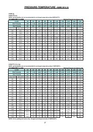
<strong>Expanding</strong> <strong>Gate</strong> <strong>Valve</strong><br />
SIZE<br />
CLASS<br />
in psi<br />
3<br />
4<br />
6<br />
8<br />
10<br />
12<br />
16<br />
20<br />
24<br />
30<br />
ANSI<br />
WORKING<br />
PRESSURE<br />
Kg/<br />
cm2<br />
STEM THREAD<br />
SIZE PITCH LEAD<br />
Operator Sizing Requirements<br />
3” - 4” Classes 600 - 900<br />
6” - 30” Classes 300 - 900<br />
RECOMMENDED<br />
OPERATING THRUST<br />
RECOMMENDED<br />
OPERATING<br />
TORQUE<br />
MAXIMUM<br />
ALLOWABLE<br />
THRUST<br />
MAXIMUM<br />
ALLOWABLE<br />
TORQUE<br />
TOTAL STEM<br />
TRAVEL TURNS<br />
TO OPEN<br />
in in in Lb Kgs Ft-Lb N-M Lb Kgs Ft-Lb N-M in mm<br />
600 1,500 105<br />
4,064 1,843 31 42<br />
1.000 0.200 0.200<br />
900 2,250 158 6,097 2,765 47 63<br />
600 1,500 105<br />
6,612 2,999 63 86<br />
1.250 0.250 0.250<br />
900 2,250 158 9,918 4,498 95 129<br />
300 750 53<br />
6,400 2,902 73 99<br />
600 1,500 105 1.500 0.286 0.286 12,800 5,805 146 197<br />
900 2,250 158 19,199 8,707 218 296<br />
300 750 53<br />
10,994 4,986 161 219<br />
600 1,500 105 2.000 0.333 0.333 21,987 9,972 322 437<br />
900 2,250 158 32,981 14,957 483 656<br />
300 750 53<br />
16,126 7,313 259 351<br />
600 1,500 105 2.250 0.333 0.333 32,251 14,626 517 702<br />
900 2,250 158 48,377 21,940 776 1,052<br />
300 750 53<br />
21,574 9,784 346 469<br />
600 1,500 105 2.250 0.333 0.333 43,152 19,570 692 939<br />
900 2,250 158 64,723 29,353 1,038 1,408<br />
300 750 53<br />
32,444 14,714 566 767<br />
600 1,500 105 2.500 0.333 0.333 64,887 29,427 1,131 1,534<br />
900 2,250 158 97,331 44,141 1,697 2,301<br />
300 750 53<br />
50,698 22,992 1,027 1,392<br />
600 1,500 105 2.875 0.400 0.400 101,396 45,984 2,053 2,784<br />
900 2,250 158 152,094 68,977 3,080 4,177<br />
300 750 53<br />
30,369 13,775 690 935<br />
2.63 0.333 0.666<br />
600 1500 105 151,845 68,876 3,449 4,676<br />
300 750 53<br />
112,888 51,205 3,063 4,153<br />
3.13 0.400 0.800<br />
600 1500 105 225,775 102,410 6,126 8,306<br />
19,944 9,045 153 207 4.03 102.3 20<br />
31,868 14,453 305 413 4.88 124 19.5<br />
48,000 21,769 546 740 7.06 179.3 25<br />
94,177 42,711 1,380 1,872 9.25 235 28<br />
127,226 57,699 2,041 2,767 11.38 289 34<br />
127,226 57,699 2,041 2,767 13.31 338 40<br />
168,876 76,588 2,944 3,992 16.63 422.4 50<br />
220,220 99,873 4,460 6,047 22.00 559 55<br />
175,865 79,771 3,994 5,415 28.13 715 42<br />
250,000 113,400 6,800 9,220 32.88 835 41<br />
Notes: 1. Recommended operating thrust and torque values are the loads required to open and close the valve. These torques do not contain service or safety factors.<br />
2. Recommended operating torque and thrust values are based on maximum working pressure at ambient temperature. To obtain expected<br />
torques at lower temperatures, contact your m&j representative.<br />
3. Actuator selection should be made based on experience and appropriate service/safety factors.<br />
4. Maximum allowable thrust and torque values are the maximum allowable loads of the valve.<br />
5. For sizes/classes not listed, contact your m&j representative.<br />
12 MJ-1761 Issued: August 2005
<strong>Expanding</strong> <strong>Gate</strong> <strong>Valve</strong><br />
Yoke Tube Flange Dimensions<br />
(2” Through 16” only)<br />
SIZE CLASS A B C D E F G H J K L<br />
6 300-900 11.31 4.25 26.31 2.56<br />
8 300-900 15.13 5.88 32.13 3.38<br />
10 300-900 17.56 6.19 39.75 3.38<br />
12 300-900 19.50 6.19 44.75 3.38<br />
16 300-900 22.75 6.13 56.75 3.50<br />
20 300-900 30.63 8.63 65.50 6.06<br />
24 300-600 38.06 9.94 81.00 5.04<br />
30 300-600 43.38 10.50 93.13 6.06<br />
3.765<br />
*5.50 (4) .69 DIA. STRADDLE CL<br />
.19 8.50 1.25<br />
3.775 *6.50 (4) .81 DIA. ON CL<br />
11<br />
3.765<br />
*5.50 (4) .69 DIA. STRADDLE CL<br />
.19 8.50 1.25<br />
3.775 *6.50 (4) .81 DIA. ON CL<br />
15<br />
3.765<br />
*5.50 (4) .69 DIA. STRADDLE CL<br />
.19 8.50 1.25<br />
3.775 *6.50 (4) .81 DIA. ON CL<br />
17.50<br />
5.015<br />
19.50<br />
.25 8.50 1.25 6.50 (4) .81 DIA. STRADDLE CL<br />
5.025<br />
5.015<br />
5.025<br />
.25 8.31 1.50 6.50 (4) .81 DIA. STRADDLE CL 24<br />
7.005<br />
7.010<br />
.31 13.50 2.63 11.75 (8) .88 DIA. STRADDLE CL 31.25<br />
7.005<br />
7.010<br />
.31 13.50 1.63 11.75 (8) .88 DIA. STRADDLE CL 37.5<br />
8.505<br />
.31 16.75 2.63 14.0 (8) 1.38 DIA STRADDLE CL 43.5<br />
8.510<br />
* These sizes have both hole patterns in the mounting flange.<br />
Issued: August 2005 MJ-1761 13
<strong>Expanding</strong> <strong>Gate</strong> <strong>Valve</strong><br />
Notes<br />
14 MJ-1761 Issued: August 2005
<strong>Expanding</strong> <strong>Gate</strong> <strong>Valve</strong><br />
Issued: August 2005 MJ-1761 15
Sales and Service<br />
SPX Process Equipment is an ISO 9001 Certified Company<br />
For information about our worldwide locations, approvals and certifications,<br />
and local representatives, please visit our web site.<br />
Web Site: www.spxprocessequipment.com E-Mail: mandjvalve@processequipment.spx.com<br />
19191 Hempstead Highway, Houston, TX 77065 Telephone: 800-231-3690 Fax: (281) 894-1332<br />
SPX Process Equipment reserves the right to incorporate our latest design and material changes without notice or obligation.<br />
Design features, materials of construction and dimensional data, as described in this bulletin, are provided for your information only<br />
and should not be relied upon unless confirmed in writing. Certified drawings are available upon request.<br />
MJ-1761 August 2005<br />
© 2005 SPX Process Equipment