Jenkins Cast Steel Valves - Associated Valve
Jenkins Cast Steel Valves - Associated Valve
Jenkins Cast Steel Valves - Associated Valve

You also want an ePaper? Increase the reach of your titles
YUMPU automatically turns print PDFs into web optimized ePapers that Google loves.
<strong>Cast</strong> <strong>Steel</strong> <strong><strong>Valve</strong>s</strong><br />
SINCE 1864<br />
JENKINS<br />
®<br />
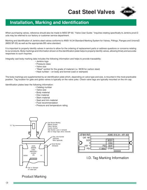
Installation, Marking and Identification<br />
When purchasing valves, reference should also be made to MSS SP-92, “<strong>Valve</strong> User Guide.” Inquiries relating specifically to <strong>Jenkins</strong> prod-<br />
ucts may be referred to our factory or customer service department.<br />
Marking and identification of <strong>Jenkins</strong> steel valves conforms to ANSI 16.34 Standard Marking System for <strong><strong>Valve</strong>s</strong>, Fittings, Flanges and Unions<br />
(MSS SP-25) as well as the appropriate BS valve standard.<br />
It is important to properly identify valves in service to allow for the ordering of replacement parts or address questions or concerns relating<br />
to our products. Body markings and information shown on the identification plate helps to properly identify valves, allowing timely and accurate<br />
responses to such inquiries.<br />
Integrally cast body marking data includes the following information and helps to provide traceability:<br />
• <strong>Jenkins</strong> logo<br />
• Pressure class<br />
• <strong>Valve</strong> size<br />
• “<strong>Steel</strong>” symbol for the grade of material (i.e. WCB for carbon steel)<br />
• Heat number – on body and bonnet (cast or stamped)<br />
The body markings are supplemented by an identification plate which, depending on valve type and size, is mounted in the most practicable<br />
position. Tag location for gate and globe valves is typically on the valve yoke. Check valve tags are typically mounted on the rim cap.<br />
Identification plates bear the following information:<br />
• Catalog number<br />
• <strong>Valve</strong> size<br />
• Body material<br />
• Disc material<br />
• Stem material<br />
• Seat and trim material<br />
• Fluid recommendation<br />
• Pressure and temperature rating<br />
I.D. Tag<br />
XXXXX<br />
(SIZE)<br />
JENKINS<br />
STEEL<br />
(MATERIAL)<br />
(CLASS)<br />
(ID)<br />
Heat Number<br />
YY<br />
zzz<br />
<strong>Cast</strong> Bonnet Marking<br />
Material Symbol<br />
Pattern Number<br />
Foundry Symbol<br />
Heat Number (cast or stamped)<br />
(Not on flange edge unless recessed)<br />
Ring Joint Number<br />
(Stamped)<br />
When applicable<br />
Serial Number<br />
(Stamped)<br />
JENKINS<br />
CAT. NO.<br />
SIZE<br />
0<br />
100° F<br />
PSI/<br />
PSI<br />
°F MAX<br />
ASME B16.34 / API 600<br />
BODY<br />
DISC<br />
SEAT<br />
STEM<br />
XXXXXX<br />
I.D. Tag Marking Information<br />
<strong>Cast</strong> or Stamped<br />
on raised pad<br />
Product Marking<br />
-3-
SINCE 1864<br />
JENKINS<br />
®<br />
<strong>Cast</strong> <strong>Steel</strong> Gate <strong><strong>Valve</strong>s</strong><br />
General Information • Class 150, 300 and 600 <strong><strong>Valve</strong>s</strong><br />
Features<br />
Flexible Wedge<br />
• Compensates for deformation of body due to pipe stresses<br />
• Will not stick when valve is closed hot and allowed to cool<br />
Welded-in Seat Ring<br />
• Seat ring is seal welded to eliminate leak path.<br />
Basic Standards<br />
These valves comply with the applicable requirements of the following standards:<br />
• API 600<br />
• API 598<br />
• ANSI B16.34<br />
• ANSI B16.10<br />
• ANSI B16.5<br />
Inspection Policy for <strong>Jenkins</strong> <strong><strong>Valve</strong>s</strong><br />
Every <strong>Jenkins</strong> cast steel valve is subjected to a 100% pressure test according to API 598 requirements.<br />
Manufacturer’s material test reports and Inspection and Test Certifications are available upon request.<br />
Some of the additional inspections and tests performed are:<br />
• Random Radiograph Inspection of Body and Bonnet <strong>Cast</strong>ings to ASME B16.34 Appendix B.<br />
• Random Chemical Composition and Mechanical Properties Verification of Fasteners to ASTMA A-193/A-194.<br />
• Liquid Penetrate Inspection of Seat Rings.<br />
• Visual Inspection of <strong>Cast</strong>ing to MSS-SP-55.<br />
• Receiving, In-process, and Final Dimensional Inspections to Relevant <strong>Valve</strong> Standards.<br />
Other inspections or tests can be performed or evaluation criteria applied when specified by the customer.<br />
Notes<br />
• Standard material is ASTM A216 Grade WCB.<br />
• Standard trim is XU (13% CR to hardface) which is suitable for a wide range of applications.<br />
• See Engineering Data section for end flange dimensions and drilling templates.<br />
-4-
<strong>Cast</strong> <strong>Steel</strong> Gate <strong><strong>Valve</strong>s</strong><br />
SINCE 1864<br />
JENKINS<br />
®<br />
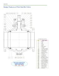
Typical Bolted Bonnet Gate <strong>Valve</strong> Features<br />
<strong>Jenkins</strong> gate valves offer the ultimate in dependable service for steam, air, gas, oil, oil vapor, and high pressure installations. All have<br />
straight-through ports to assure minimum turbulence, erosion, and resistance to flow. They are available in a wide variety of trims.<br />
-5-<br />
1. Body: Body is cast to provide liberal strength to meet operating<br />
conditions and to permit unobstructed flow. Turbulence, erosion<br />
and pressure drop are minimized.<br />
Flanged End-<strong>Jenkins</strong> cast steel gate valves are available in<br />
flanged end and butt weld ends. All flanged and butt welding<br />
end valves are designed to conform to ANSI B16.5 and ANSI<br />
B16.34 standards.<br />
2. Integral Yoke & Bonnet: Some designs incorporate a twopiece<br />
bonnet and yoke. All bonnet assemblies are cast and<br />
finished to the same exacting tolerances as the bodies for<br />
accurate alignment of stems and ease of sealing. Bonnet joint<br />
varies from flat face gasket-joint to ring-type bonnet joint,<br />
depending on class.<br />
3. Seat Rings: Seat rings are seal welded to eliminate leak path<br />
behind rings and for long trouble-free service. The surfaces are<br />
precision ground to fit accurately with the disc.<br />
4. Disc: One piece flexible disc provides accurate alignment of<br />
mating seating surfaces so the valve can absorb piping strains<br />
without leakage. Also, it avoids any tendency to stick in the<br />
seated position. <strong><strong>Valve</strong>s</strong> are also furnished with solid wedge<br />
discs that have proved successful in millions of applications.<br />
5. Stem: The tee-head disc-stem connection prevents lateral<br />
strain on the stem for smooth, easy operation. Accurately cut<br />
threads engage the yoke sleeve for positive control of disc<br />
position.<br />
6. Yoke Sleeve<br />
7. Handwheel Nut<br />
8. Yoke Sleeve Retaining Nut<br />
9. Packing: Packing contains corrosion inhibitor to avoid stem<br />
pitting. Stuffing box is deep, assuring long packing life.<br />
10. Gland: Gland is a two-piece ball-type which exerts even pressure<br />
on the packing without binding the stem.<br />
11. Gland Flange<br />
12. Gland Eye Bolts: Eyebolts swing aside for ease in repacking<br />
the stuffing box.<br />
13. Gland Eye Bolt Nuts<br />
14. Bonnet Gasket<br />
15. Bonnet Studs: Number is dependent on valve size and class.<br />
16. Bonnet Nuts: Number is dependent on valve size and class.<br />
17. Groove-Pin<br />
18. Bonnet Bushing<br />
19.<br />
20.<br />
Handwheel: Gate valves can also be supplied with gear or<br />
motor operators.<br />
Hydraulic Grease Fitting: Hydraulic grease fitting provides<br />
for lubrication of yoke sleeve bearing surfaces (not shown).
SINCE 1864<br />
JENKINS<br />
®<br />
<strong>Cast</strong> <strong>Steel</strong> Gate <strong><strong>Valve</strong>s</strong><br />
Figure J1009B8F<br />
Class 150 • Outside Screw & Yoke • Flexible Wedge Disc<br />
Material of Construction<br />
Description<br />
Material<br />
Body<br />
WCB<br />
Bonnet<br />
WCB<br />
Seat Rings<br />
Hardfaced<br />
Disc<br />
13% CR Overlay<br />
Stem<br />
410 SS<br />
Packing<br />
Graphite<br />
Bonnet Gasket<br />
Soft Iron<br />
Back Seat<br />
410 SS<br />
Yoke Sleeve<br />
D2 Ni-Resist<br />
Retaining Nut<br />
Malleable<br />
Gland<br />
<strong>Steel</strong><br />
Gland Flange<br />
<strong>Steel</strong><br />
Eye Bolt<br />
<strong>Steel</strong><br />
Eye Bolt Nuts<br />
A563 Gr. A or O<br />
Pins<br />
<strong>Steel</strong><br />
Bonnet Studs<br />
A193 Gr. B7<br />
Bonnet Nuts<br />
A194 Gr. 2H<br />
Handwheel<br />
Malleable or Ductile<br />
Handwheel Nut<br />
Ductile or <strong>Steel</strong><br />
I.D. Tags<br />
SS<br />
I.D. Pins<br />
<strong>Steel</strong><br />
Spacer<br />
<strong>Steel</strong><br />
Figure J1009B8F<br />
Flanged<br />
Size Range:<br />
2 through 12 inches<br />
Pressure Temperature Rating<br />
Carbon <strong>Steel</strong><br />
ASTM A216 Grade WCB<br />
285 psi @ -20°F to 100°F<br />
Note<br />
• 2" only-solid wedge<br />
C<br />
Industry Standards<br />
<strong>Steel</strong> <strong><strong>Valve</strong>s</strong> ANSI B16.34<br />
Face-to-Face/End-to-End ANSI B16.10<br />
Flange Dimensions ANSI B16.5<br />
Basic Design API 600<br />
Testing API 598<br />
A<br />
B<br />
Dimensions and Weights<br />
<strong>Valve</strong><br />
Size<br />
Weight<br />
(pounds)<br />
Dimensions (inches)<br />
A B C<br />
2 40 7.00 14.88 7.87<br />
2 1 /2 57 7.50 18.11 7.87<br />
3 75 8.00 20.47 9.84<br />
4 114 9.00 23.90 9.84<br />
5 155 10.00 27.88 12.00<br />
6 189 10.50 31.61 13.78<br />
8 310 11.50 38.19 13.78<br />
10 455 13.00 45.59 15.75<br />
12 650 14.00 54.84 17.72<br />
-6-
Figure J1010B8F<br />
<strong>Cast</strong> <strong>Steel</strong> Gate <strong><strong>Valve</strong>s</strong><br />
SINCE 1864<br />
JENKINS<br />
®<br />
Class 300 • Outside Screw & Yoke • Flexible Wedge Disc<br />
Figure J1010B8F<br />
Flanged<br />
Size Range:<br />
2 through 12 inches<br />
Pressure Temperature Rating<br />
Carbon <strong>Steel</strong><br />
ASTM A216 Grade WCB<br />
740 psi @ -20°F to 100°F<br />
Note<br />
• 2" only-solid wedge<br />
Material of Construction<br />
Description<br />
Material<br />
Body<br />
WCB<br />
Bonnet<br />
WCB<br />
Seat Rings<br />
Hardfaced<br />
Disc<br />
13% CR Overlay<br />
Stem<br />
410 SS<br />
Packing<br />
Graphite<br />
Bonnet Gasket<br />
Spiral Wound<br />
Back Seat<br />
410 SS<br />
Yoke Sleeve<br />
D2 Ni-Resist<br />
Retaining Nut<br />
Malleable<br />
Gland<br />
<strong>Steel</strong><br />
Gland Flange<br />
<strong>Steel</strong><br />
Eye Bolt<br />
<strong>Steel</strong><br />
Eye Bolt Nuts<br />
A563 Gr. A or O<br />
Pins<br />
<strong>Steel</strong><br />
Bonnet Studs<br />
A193 Gr. B7<br />
Bonnet Nuts<br />
A194 Gr. 2H<br />
Handwheel<br />
Malleable or Ductile<br />
Handwheel Nut<br />
Ductile or <strong>Steel</strong><br />
I.D. Tags<br />
SS<br />
I.D. Pins<br />
<strong>Steel</strong><br />
Spacer<br />
<strong>Steel</strong><br />
Grease Fittings<br />
<strong>Steel</strong><br />
Industry Standards<br />
<strong>Steel</strong> <strong><strong>Valve</strong>s</strong> ANSI B16.34<br />
Face-to-Face/End-to-End ANSI B16.10<br />
Flange Dimensions ANSI B16.5<br />
Basic Design API 600<br />
Testing API 598<br />
C<br />
Dimensions and Weights<br />
-7-<br />
<strong>Valve</strong><br />
Size<br />
Weight<br />
(pounds)<br />
Dimensions (inches)<br />
A B C<br />
2 48 8.50 15.75 7.87<br />
2 1 /2 79 9.50 18.98 9.84<br />
3 114 11.12 21.42 9.84<br />
4 172 12.00 24.80 11.81<br />
5 235 15.00 28.38 12.00<br />
6 339 15.88 32.48 15.75<br />
8 500 16.50 39.57 15.75<br />
10 760 18.00 49.50 18.00<br />
12 1020 19.75 57.25 20.00<br />
A<br />
B
SINCE 1864<br />
JENKINS<br />
®<br />
<strong>Cast</strong> <strong>Steel</strong> Gate <strong><strong>Valve</strong>s</strong><br />
Figure J1012B8F<br />
Class 600 • Outside Screw & Yoke • Flexible Wedge Disc<br />
Material of Construction<br />
Description<br />
Material<br />
Body<br />
WCB<br />
Bonnet<br />
WCB<br />
Seat Rings<br />
Hardfaced<br />
Disc<br />
13% CR Overlay<br />
Stem<br />
410 SS<br />
Packing<br />
Graphite<br />
Bonnet Gasket<br />
Ring Joint<br />
Back Seat<br />
410 SS<br />
Yoke Sleeve<br />
D2 Ni-Resist<br />
Retaining Nut<br />
Malleable<br />
Gland<br />
<strong>Steel</strong><br />
Gland Flange<br />
<strong>Steel</strong><br />
Eye Bolt<br />
<strong>Steel</strong><br />
Eye Bolt Nuts<br />
A563 Gr. A or O<br />
Pins<br />
<strong>Steel</strong><br />
Bonnet Studs<br />
A193 Gr. B7<br />
Bonnet Nuts<br />
A194 Gr. 2H<br />
Handwheel<br />
Malleable or Ductile<br />
Handwheel Nut<br />
Ductile or <strong>Steel</strong><br />
I.D. Tags<br />
SS<br />
I.D. Pins<br />
<strong>Steel</strong><br />
Spacer<br />
<strong>Steel</strong><br />
Grease Fittings<br />
<strong>Steel</strong><br />
Figure J1012B8F<br />
Flanged<br />
Size Range:<br />
2 through 12 inches<br />
Pressure Temperature Rating<br />
Carbon <strong>Steel</strong><br />
ASTM A216 Grade WCB<br />
1480 psi @ -20°F to 100°F<br />
Note<br />
• 2" only-solid wedge<br />
C<br />
Industry Standards<br />
<strong>Steel</strong> <strong><strong>Valve</strong>s</strong> ANSI B16.34<br />
Face-to-Face/End-to-End ANSI B16.10<br />
Flange Dimensions ANSI B16.5<br />
Basic Design API 600<br />
Testing API 598<br />
A<br />
B<br />
Dimensions and Weights<br />
<strong>Valve</strong><br />
Size<br />
Weight<br />
(pounds)<br />
Dimensions (inches)<br />
A B C<br />
2 84 11.50 18.00 10.00<br />
2 1 /2 130 13.00 20.50 10.00<br />
3 160 14.00 22.62 12.00<br />
4 300 17.00 28.62 14.00<br />
6 640 22.00 38.62 18.00<br />
8 1080 26.00 47.25 20.00<br />
10 1550 31.00 58.25 25.00<br />
12 2100 33.00 68.12 28.00<br />
-8-
<strong>Cast</strong> <strong>Steel</strong> Globe <strong><strong>Valve</strong>s</strong><br />
SINCE 1864<br />
JENKINS<br />
®<br />
General Information • Class 150, 300 and 600 <strong><strong>Valve</strong>s</strong><br />
Features<br />
Welded-in Seat Ring<br />
• Seat ring is seal welded to eliminate leak path. behind rings<br />
Basic Standards<br />
These valves comply with the applicable requirements of the following standards:<br />
• API 598<br />
• ANSI B16.34<br />
• ANSI B16.10<br />
• ANSIB16.5<br />
Notes<br />
• Standard material is ASTM A216 Grade WCB.<br />
• Standard trim is XU (13% CR to hardface) which is suitable for a wide range of applications.<br />
• See Engineering Data section for end flange dimensions and drilling templates.<br />
-9-
SINCE 1864<br />
JENKINS<br />
®<br />
<strong>Cast</strong> <strong>Steel</strong> Globe <strong><strong>Valve</strong>s</strong><br />
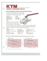
Typical Globe <strong>Valve</strong> Features<br />
<strong>Jenkins</strong> globe valves are highly efficient for services requiring frequent operation and throttling when pressure drop across the valve is about<br />
20% of inlet pressure. Closer throttling, creating higher pressure drops may cause cavitation or excessive velocities which could cause high<br />
noise levels, vibration and possible damage to the valve or adjacent piping. Globe valves can be equipped with optional operators and are<br />
available with a variety of trims to match service requirements.<br />
1. Body: Body is cast with heavy sections reinforced at points<br />
subjected to the greatest stress. <strong><strong>Valve</strong>s</strong> are available in both<br />
flanged and butt welding ends. All conform to ANSI specifications.<br />
2. Bonnet<br />
3. Bonnet Seat Ring<br />
4. Disc<br />
5. Disc Stem Ring: Disc Stem Ring connects the disc to the stem,<br />
permitting the disc to swivel and aid in securing tight seating for<br />
trouble-free service.<br />
6. Disc Washer<br />
7. Stem: Stem has long engagement with yoke bushing for accurate<br />
seating.<br />
8. Bonnet Bushing<br />
9. Yoke Bushing<br />
10. Wheel Nut<br />
11. Packing<br />
12. Gland: Gland is a two-piece, ball-type which exerts even<br />
pressure on the packing without binding the stem.<br />
13. Gland Flange<br />
14. Gland Eye Bolts: Eye bolts are securely fastened to the bonnet<br />
yet swing away to permit easy access to the stuffing box.<br />
15. Bonnet Gasket: Bonnet gasket provides a positive seal against<br />
leakage. Class 150 and 300 valves have a male/female bonnet<br />
joint. A ring-type gasket is employed in Class 600.<br />
16. Bonnet Studs<br />
17. Bonnet Nuts<br />
18. Pin<br />
19. Handwheel<br />
-10-
Figure J1040B2<br />
<strong>Cast</strong> <strong>Steel</strong> Globe <strong><strong>Valve</strong>s</strong><br />
SINCE 1864<br />
JENKINS<br />
®<br />
Class 150 • Outside Screw & Yoke • Bolted Bonnet<br />
Figure 1040B2<br />
Flanged<br />
Size Range:<br />
2 through 12 inches<br />
Pressure Temperature Rating<br />
Carbon <strong>Steel</strong><br />
ASTM A216 Grade WCB<br />
285 psi @ -20°F to 100°F<br />
Material of Construction<br />
Description<br />
Material<br />
Body<br />
WCB<br />
Bonnet<br />
WCB<br />
Seat Rings<br />
Hardfaced<br />
Disc<br />
13% CR Overlay<br />
Stem<br />
410 SS<br />
Packing<br />
Graphite<br />
Bonnet Gasket<br />
Soft Iron<br />
Back Seat<br />
410 SS<br />
Disc Stem Nut<br />
410 SS<br />
Disc Washer<br />
Carbon <strong>Steel</strong><br />
Gland<br />
410 SS<br />
Gland Flange<br />
WCB<br />
Eye Bolt<br />
<strong>Steel</strong><br />
Eye Bolt Nuts<br />
A563 Gr. A or O<br />
Pins –<br />
Bonnet Studs<br />
A193 Gr. B7<br />
Bonnet Nuts<br />
A194 Gr. 2H<br />
Handwheel<br />
WCB<br />
Handwheel Nut<br />
A194 Gr. 2H<br />
I.D. Tags<br />
SS<br />
I.D. Pins<br />
<strong>Steel</strong><br />
Industry Standards<br />
<strong>Steel</strong> <strong><strong>Valve</strong>s</strong> ANSI B16.34<br />
Face-to-Face/End-to-End ANSI B16.10<br />
Flange Dimensions ANSI B16.5<br />
Testing API 598<br />
C<br />
Dimensions and Weights<br />
<strong>Valve</strong> Weight Dimensions (inches)<br />
Size (pounds) A B C<br />
B<br />
2 51 8.00 13.62 7.87<br />
2 1 /2 62 8.50 15.16 7.87<br />
3 75 9.50 16.61 9.84<br />
4 132 11.50 19.84 11.81<br />
5 199 14.00 23.00 12.00<br />
6 231 16.00 23.62 15.75<br />
8 525 19.50 24.65 15.75<br />
10 900 24.50 28.03 17.72<br />
12 900 27.50 39.50 24.00<br />
A<br />
-11-
SINCE 1864<br />
JENKINS<br />
®<br />
<strong>Cast</strong><br />
<strong>Steel</strong> Globe <strong><strong>Valve</strong>s</strong><br />
Figure J1042B2<br />
Class 300 • Outside Screw & Yoke • Bolted Bonnet<br />
Material of Construction<br />
Description<br />
Material<br />
Body<br />
WCB<br />
Bonnet<br />
WCB<br />
Seat Rings<br />
Hardfaced<br />
Disc<br />
13% CR Overlay<br />
Stem<br />
410 SS<br />
Packing<br />
Graphite<br />
Bonnet Gasket<br />
Spiral Wound<br />
Back Seat<br />
410 SS<br />
Disc Stem Nut<br />
410 SS<br />
Disc Washer<br />
Carbon <strong>Steel</strong><br />
Gland<br />
410 SS<br />
Gland Flange<br />
WCB<br />
Eye Bolt<br />
<strong>Steel</strong><br />
Eye Bolt Nuts<br />
A563 Gr. A or O<br />
Pins –<br />
Bonnet Studs<br />
A193 Gr. B7<br />
Bonnet Nuts<br />
A194 Gr. 2H<br />
Handwheel<br />
WCB<br />
Handwheel Nut<br />
A194 Gr. 2H<br />
I.D. Tags<br />
SS<br />
I.D. Pins<br />
<strong>Steel</strong><br />
Figure J1042B2<br />
Flanged<br />
Size Range:<br />
2 through 12 inches<br />
Pressure Temperature Rating<br />
Carbon <strong>Steel</strong><br />
ASTM A216 Grade WCB<br />
740 psi @ -20°F to 100°F<br />
Industry Standards<br />
C<br />
<strong>Steel</strong> <strong><strong>Valve</strong>s</strong> ANSI B16.34<br />
Face-to-Face/End-to-End ANSI B16.10<br />
Flange Dimensions ANSI B16.5<br />
Testing API 598<br />
Dimensions and Weights<br />
B<br />
<strong>Valve</strong> Weight Dimensions (inches)<br />
Size (pounds) A B C<br />
A<br />
2 59 10.50 16.65 7.87<br />
2 1 /2 88 11.50 17.83 9.84<br />
3 128 12.50 20.31 9.84<br />
4 191 14.00 22.91 13.78<br />
5 290 15.75 27.50 12.00<br />
6 345 17.50 25.91 17.72<br />
8 750 22.00 36.00 20.00<br />
10 1100 24.50 41.65 34.02<br />
12 1100 28.00 37.25 24.00<br />
-12-
Figure J1044B2<br />
<strong>Cast</strong> <strong>Steel</strong> Globe <strong><strong>Valve</strong>s</strong><br />
SINCE 1864<br />
JENKINS<br />
®<br />
Class 600 • Outside Screw & Yoke • Bolted Bonnet<br />
Figure J1044B2<br />
Flanged<br />
Size Range:<br />
2 through 8 inches<br />
Pressure Temperature Rating<br />
Carbon <strong>Steel</strong><br />
ASTM A216 Grade WCB<br />
1480 psi @ -20°F to 100°F<br />
Material of Construction<br />
Description<br />
Material<br />
Body<br />
WCB<br />
Bonnet<br />
WCB<br />
Seat Rings<br />
Hardfaced<br />
Disc<br />
13% CR Overlay<br />
Stem<br />
410 SS<br />
Packing<br />
Graphite<br />
Bonnet Gasket<br />
Ring Joint<br />
Back Seat<br />
410 SS<br />
Disc Stem Nut<br />
410 SS<br />
Disc Washer<br />
Carbon <strong>Steel</strong><br />
Gland<br />
410 SS<br />
Gland Flange<br />
WCB<br />
Eye Bolt<br />
<strong>Steel</strong><br />
Eye Bolt Nuts<br />
A563 Gr. A or O<br />
Pins –<br />
Bonnet Studs<br />
A193 Gr. B7<br />
Bonnet Nuts<br />
A194 Gr. 2H<br />
Handwheel<br />
WCB<br />
Handwheel Nut<br />
A194 Gr. 2H<br />
I.D. Tags<br />
SS<br />
I.D. Pins<br />
SS<br />
Industry Standards<br />
<strong>Steel</strong> <strong><strong>Valve</strong>s</strong> ANSI B16.34<br />
Face-to-Face/End-to-End ANSI B16.10<br />
Flange Dimensions ANSI B16.5<br />
Testing API 598<br />
C<br />
Dimensions and Weights<br />
<strong>Valve</strong> Weight Dimensions (inches)<br />
Size (pounds) A B C<br />
B<br />
2 88 11.50 18.75 10.00<br />
2 1 /2 126 13.00 20.25 10.00<br />
3 160 14.00 23.00 14.00<br />
4 270 17.00 26.50 18.00<br />
6 550 22.00 27.00 20.00<br />
8 1000 26.00 28.50 22.00<br />
A<br />
-13-
SINCE 1864<br />
JENKINS<br />
®<br />
<strong>Cast</strong> <strong>Steel</strong> Check <strong><strong>Valve</strong>s</strong><br />
General Information • Class 150, 300 and 600 <strong><strong>Valve</strong>s</strong><br />
Features<br />
Disc Type<br />
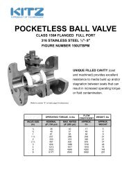
• Class 150 valves-2"-12" and Class 300 valves-sizes 2"-8" feature an internally mounted hinge pin<br />
which eliminates a leak path<br />
• For class 600 valves, a ring joint bonnet gasket assures positive seal against leakage and accurate<br />
alignment of moving parts<br />
Welded-in Seat Ring<br />
• Seat ring is seal welded to eliminate leak path. behind rings<br />
Basic Standards<br />
These valves comply with the applicable requirements of the following standards:<br />
• API 598<br />
• ANSI B16.34<br />
• ANSI B16.10<br />
• ANSI B16.5<br />
Notes<br />
• Standard material is ASTM A216 Grade WCB.<br />
• Standard trim is XU (13% CR to hardface) which is suitable for a wide range of applications.<br />
• See Engineering Data section for end flange dimensions and drilling templates.<br />
-14-
<strong>Cast</strong> <strong>Steel</strong> Swing Check <strong>Valve</strong><br />
SINCE 1864<br />
JENKINS<br />
®<br />
Typical Swing Check <strong>Valve</strong> Features<br />
Check valves are automatically actuated. They are opened and sustained in the open position by the force of velocity pressure, and<br />
closed by the force of gravity. Seating load and resultant tightness is dependent upon back pressure. The disc and associated moving<br />
parts may be in a constant state of movement if the velocity pressure is not sufficient to hold the valve in a wide open and stable<br />
position. Premature wear and noisy operation or vibration of the moving parts can be avoided by selecting the size of check valve on the<br />
basis of flow conditions. The minimum velocity required to hold a swing check valve in the wide open and stable position has been<br />
developed by analysis of extensive test data and is expressed by the formula:<br />
v= 60 v<br />
The value for v is equal to flow in feet per second and v is the specific volume of fluid in cubic feet per pound. Sizing swing check valves<br />
on this basis may often result in the use of valves that are smaller than the pipe in which they are used, necessitating the use of reducers<br />
for installation. The pressure drop will be no greater than that of the larger valve that is only partially open, and valve life will be greatly<br />
extended. The added bonus, of course, is the lower cost of the smaller valve.<br />
There is no tendency for the seating surfaces of swing check valves to gall or score, because the disc meets the flat seat squarely<br />
without rubbing contact upon closing.<br />
<strong>Jenkins</strong> cast steel swing check valves can be furnished with outside lever and adjustable weight when so ordered. With the lever and<br />
weight mounted so that the weight assists the disc in closing, the valve closes more rapidly when flow stops, thus minimizing reversal of<br />
flow and resultant surge and shock. With the lever and weight mounted to balance the weight of the disc, the valve becomes more<br />
sensitive to low inlet velocities.<br />
Swing check valves are used to prevent reversal of flow in horizontal or vertical pipe lines. In vertical lines, or for any angle from horizontal<br />
to vertical, they can be used for upward flow only.<br />
1. Body: Strong construction assures<br />
maximum safety over the recommended<br />
pressure and temperature<br />
range. Both flange and butt weld ends<br />
are available.<br />
2. Cap: permits access to hinge and<br />
disc without removing valve from line.<br />
3. Disc: is designed to close on its own<br />
weight to stop backflow from gaining<br />
sufficient velocity to create damaging<br />
shock.<br />
4. Disc Nut Pin<br />
5. Hinge<br />
6. Cap Studs<br />
7. Cap Stud Nuts<br />
8. Cap Gasket<br />
9. Body Seat Ring (welded in)<br />
10. Disc Washer<br />
12. Disc Nut<br />
-15-
SINCE 1864<br />
JENKINS<br />
®<br />
<strong>Cast</strong> <strong>Steel</strong> Swing Check <strong>Valve</strong><br />
Figure<br />
J1025B2<br />
Class 150 • Bolted Cap<br />
Material of Construction<br />
Description<br />
Material<br />
Body<br />
WCB<br />
Cap<br />
WCB<br />
Seat Ring<br />
Hardfaced<br />
Disc<br />
13% CR Overlay<br />
Hinge<br />
WCB<br />
Pins, Hinge<br />
410 SS<br />
Disc Washer<br />
<strong>Steel</strong><br />
Cap Screw<br />
A307 Gr. B<br />
Cap Gasket<br />
Soft Iron<br />
Cap Studs<br />
A193 Gr. B<br />
Cap Nuts<br />
A194 Gr. 2H<br />
I.D. Tags<br />
SS<br />
I.D. Pins<br />
<strong>Steel</strong><br />
Figure J1025B2<br />
Flanged<br />
Size Range:<br />
2 through 12 inches<br />
Pressure Temperature Rating<br />
Carbon <strong>Steel</strong><br />
ASTM A216 Grade WCB<br />
285 psi @ -20°F to 100°F<br />
Industry Standards<br />
<strong>Steel</strong> <strong><strong>Valve</strong>s</strong> ANSI B16.34<br />
Face-to-Face/End-to-End ANSI B16.10<br />
Flange Dimensions ANSI B16.5<br />
Testing API 598<br />
B<br />
Dimensions and Weights<br />
<strong>Valve</strong> Weight Dimensions (inches)<br />
Size (pounds) A B<br />
A<br />
2 33 8.00 6.75<br />
2 1 /2 57 8.50 7.12<br />
3 59 9.50 7.38<br />
4 93 11.50 8.50<br />
5 152 13.00 9.50<br />
6 165 14.00 10.25<br />
8 275 19.50 11.88<br />
10 440 24.50 13.88<br />
12 680 27.50 15.75<br />
-16-
Figure<br />
J1026B2<br />
<strong>Cast</strong> <strong>Steel</strong> Swing Check <strong>Valve</strong><br />
SINCE 1864<br />
JENKINS<br />
®<br />
Class 300 • Bolted Cap<br />
Figure J1026B2<br />
Flanged<br />
Size Range:<br />
2 through 12 inches<br />
Pressure Temperature Rating<br />
Carbon <strong>Steel</strong><br />
ASTM A216 Grade WCB<br />
740 psi @ -20°F to 100°F<br />
Material of Construction<br />
Description<br />
Material<br />
Body<br />
WCB<br />
Cap<br />
WCB<br />
Seat Ring<br />
Hardfaced<br />
Disc<br />
13% CR Overlay<br />
Hinge<br />
WCB<br />
Pins, Hinge<br />
410 SS<br />
Disc Washer<br />
<strong>Steel</strong><br />
Cap Screw<br />
A307 Gr. B<br />
Cap Gasket<br />
Spiral Wound<br />
Cap Studs<br />
A193 Gr. B<br />
Cap Nuts<br />
A194 Gr. 2H<br />
I.D. Tags<br />
SS<br />
I.D. Pins<br />
<strong>Steel</strong><br />
Industry Standards<br />
<strong>Steel</strong> <strong><strong>Valve</strong>s</strong> ANSI B16.34<br />
Face-to-Face/End-to-End ANSI B16.10<br />
Flange Dimensions ANSI B16.5<br />
Testing API 598<br />
Dimensions and Weights<br />
B<br />
<strong>Valve</strong> Weight Dimensions (inches)<br />
Size (pounds) A B<br />
2 46 10.50 6.75<br />
2 1 /2 66 11.50 7.38<br />
3 86 12.50 8.50<br />
4 154 14.00 9.25<br />
5 255 15.75 10.62<br />
6 276 17.50 11.88<br />
8 420 21.00 13.38<br />
10 640 24.50 13.88<br />
12 1000 28.00 16.62<br />
A<br />
-17-
SINCE 1864<br />
JENKINS<br />
®<br />
<strong>Cast</strong> <strong>Steel</strong> Swing Check <strong>Valve</strong><br />
Figure<br />
J1028B2<br />
Class 600 • Bolted Cap<br />
Material of Construction<br />
Description<br />
Material<br />
Body<br />
WCB<br />
Cap<br />
WCB<br />
Seat Ring<br />
Hardfaced<br />
Disc<br />
13% CR Overlay<br />
Hinge<br />
WCB<br />
Pins, Hinge<br />
410 SS<br />
Disc Washer<br />
<strong>Steel</strong><br />
Cap Screw<br />
A307 Gr. B<br />
Cap Gasket<br />
Ring Joint<br />
Cap Studs<br />
A193 Gr. B<br />
Cap Nuts<br />
A194 Gr. 2H<br />
I.D. Tags<br />
SS<br />
I.D. Pins<br />
<strong>Steel</strong><br />
Figure J1028B2<br />
Flanged<br />
Size Range:<br />
2 through 12 inches<br />
Pressure Temperature Rating<br />
Carbon <strong>Steel</strong><br />
ASTM A216 Grade WCB<br />
1480 psi @ -20°F to 100°F<br />
Industry Standards<br />
<strong>Steel</strong> <strong><strong>Valve</strong>s</strong> ANSI B16.34<br />
Face-to-Face/End-to-End ANSI B16.10<br />
Flange Dimensions ANSI B16.5<br />
Testing API 598<br />
B<br />
Dimensions and Weights<br />
<strong>Valve</strong> Weight Dimensions (inches)<br />
Size (pounds) A B<br />
A<br />
2 62 11.50 6.88<br />
2 1 /2 84 13.00 7.88<br />
3 115 14.00 9.12<br />
4 192 17.00 11.62<br />
6 495 22.00 14.25<br />
8 780 26.00 15.75<br />
10 1400 31.00 18.12<br />
12 1750 33.00 20.50<br />
-18-
<strong>Cast</strong> <strong>Steel</strong> <strong><strong>Valve</strong>s</strong><br />
SINCE 1864<br />
JENKINS<br />
®<br />
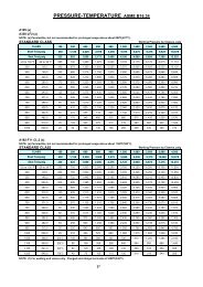
Pressure-Temperature Ratings<br />
Pressure-Temperature Ratings<br />
(comply with ANSI B16.34-1981 – Standard Class)<br />
Bolted Bonnet <strong><strong>Valve</strong>s</strong><br />
Class Temp. Working Pressures, psig Class Temp. Working Pressures, psig<br />
A216 A217 A217 A217 A352 A352 A216 A217 A217 A217 A362 A362<br />
F WCB C5W C6 WC9 LCB LC3 F WCB C5W C6 WC9 LCB LC3<br />
-20 t0 100° 285 290 290 290 265 290 -20 to 100° 1480 1500 1500 1500 1390 1500<br />
200 260 260 260 260 250 260 200 1350 1500 1425 1430 1315 1500<br />
300 230 230 230 230 230 230 300 1315 1455 1345 1355 1275 1465<br />
400 200 200 200 200 200 200 400 1270 1410 1315 1295 1235 1410<br />
500 170 170 170 170 170 170 500 1200 1330 1285 1280 1165 1330<br />
600 140 140 140 140 140 140 600 1095 1210 1210 1210 1065 1210<br />
650 125 125 125 125 125 125 650 1075 1210 1210 1210 1065 1210<br />
700 110 110 110 110 – – 700 1065 1135 1135 1135 – –<br />
Class<br />
Class<br />
150 600<br />
800 80 80 80 80 – – 800 825 995 1015 1015 – –<br />
850 651 65 65 65 – – 850 5351 880 975 975 – –<br />
900 501 50 50 50 – – 900 3451 705 900 900 – –<br />
950 351 35 35 35 – – 950 2051 520 755 755 – –<br />
1000 201 20 20 20 – – 1000 1051 365 445 535 – –<br />
1050 – 202 20 20 – – 1050 _ 280 275 400 _ _<br />
1100 _ 202 _ _ _ _ 1150 _ 205 190 225 _ _<br />
1150 _ 202 _ _ _ _ 1150 _ 140 _ _ _ _<br />
1200 _ 202 _ _ _ _ 1200 _ 90 _ _ _ _<br />
-20 to 100° 740 750 750 750 695 750 -20 to 100° 2220 2250 2250 2250 2085 2250<br />
200 675 750 710 715 655 750 200 2025 2250 2135 2150 1970 2250<br />
300 655 730 675 675 640 730 300 1970 2185 2020 2030 1915 2185<br />
400 635 705 660 650 620 705 400 1900 2115 1975 1945 1850 2115<br />
500 600 665 640 640 585 665 500 1795 1995 1925 1920 1745 1995<br />
600 550 605 605 605 535 605 600 1640 1815 1815 1815 1600 1815<br />
650 535 590 590 590 525 590 650 1610 1765 1765 1765 1570 1765<br />
700 535 570 570 570 _ _ 700 1600 1705 1705 1705 _ _<br />
750 505 530 530 530 _ _ 750 1510 1595 1595 1595 _ _<br />
Class<br />
Class<br />
300 900<br />
800 410 500 510 510 _ _ 800 1235 1490 1525 1525 _ _<br />
850 2701 440 485 485 _ _ 850 8051 1315 1460 1460 _ _<br />
900 1701 355 450 450 _ _ 900 5151 1060 1350 1350 _ _<br />
950 1051 260 380 380 _ _ 950 3101 780 1130 1130 _ _<br />
1000 501 190 225 270 _ _ 1000 1551 575 670 805 _ _<br />
1050 _ 140 140 200 _ _ 1050 _ 420 410 595 _ _<br />
1100 _ 105 95 115 _ _ 1100 _ 310 290 340 _ _<br />
1150 _ 70 _ _ _ _ 1150 _ 205 _ _ _ _<br />
1200 _ 45 _ _ _ _ 1200 _ 135 _ _ _ _<br />
-20 to 100° 990 1000 1000 1000 925 1000 -20 to 100° 3705 3750 3750 3750 3470 3750<br />
200 900 1000 950 955 875 1000 200 3375 3750 3560 3580 3280 3750<br />
300 875 970 895 905 850 970 300 3280 3640 3365 3385 3190 3640<br />
400 845 940 880 865 825 940 400 3170 3530 3290 3240 3085 3530<br />
500 800 885 855 855 775 885 500 2995 3325 3210 3200 2910 3325<br />
600 730 805 805 805 710 805 600 2735 3025 3025 3025 2665 3025<br />
650 715 785 785 785 695 785 650 2685 2940 2940 2940 2615 2940<br />
700 710 755 755 755 _ _ 700 2665 2840 2840 2840 _ _<br />
750 670 710 710 710 _ _ 750 2520 2660 2660 2660 _ _<br />
Class<br />
Class<br />
400 1500<br />
800 550 665 675 675 _ _ 800 2060 2485 2540 2540 _ _<br />
850 3551 585 650 650 _ _ 850 13401 2195 2435 2435 _ _<br />
900 2301 470 600 600 _ _ 900 8601 1765 2245 2245 _ _<br />
950 1401 350 505 505 _ _ 950 5151 1305 1885 1885 _ _<br />
1000 701 255 300 355 _ _ 1000 2601 960 1115 1340 _ _<br />
1050 _ 190 185 265 _ _ 1050 _ 705 685 995 _ _<br />
1100 _ 140 130 150 _ _ 1100 _ 515 480 565 _ _<br />
1150 _ 90 _ _ _ _ 1150 _ 345 _ _ _ _<br />
1200 _ 60 _ _ _ _ 1200 _ 225 _ _ _ _<br />
-19-
SINCE 1864<br />
JENKINS<br />
®<br />
Technical Data<br />
Temperature Conversions<br />
Centigrade to Fahrenheit – Fahrenheit to Centigrade<br />
Locate temperature in middle column. If in degrees Centigrade, read Fahrenheit equivalent in <br />
right-hand column; if in degrees Fahrenheit, read Centigrade equivalent in left-hand column.<br />
Conversion Formulas: °C = 5/9 (°F-32)<br />
°F = 9/5 (°C+32)<br />
-20-
SINCE 1864<br />
JENKINS<br />
®<br />
Performance In Any Application<br />
In any fluid handling system, valves are the controlling element: starting or stopping flow, regulating or throttling<br />
flow, preventing backflow, or relieving and regulating pressure.<br />
<strong>Jenkins</strong> valves are universally accepted by industry for virtually every application ranging from vacuum pressures<br />
and cryogenic temperatures to elevated pressures and temperatures.<br />
Gate <strong><strong>Valve</strong>s</strong><br />
Since <strong>Jenkins</strong> valves are used in a variety of applications, the following descriptions may provide a basic guideline<br />
in the selection of steel valves.<br />
Gate valves serve as efficient stop valves with flow in either direction. They are commonly used where a minimum<br />
pressure drop is important. Throttling is not recommended because partially open gate valves exhibit flow<br />
characteristics not conducive to accurate and consistent flow control. Also, the valves may be damaged by the<br />
high velocity across the seats. They function best fully open or fully closed.<br />
Globe <strong><strong>Valve</strong>s</strong><br />
Swing Check <strong><strong>Valve</strong>s</strong><br />
Globe valves are ideal for throttling service. Their flow characteristics permit accurate and repeatable flow<br />
control. However, caution must be exercised to avoid extremely close throttling when pressure drop exceeds<br />
20%. This creates excessive noise, vibration and possible damage to valves and piping. When these conditions<br />
are anticipated, consult <strong>Jenkins</strong> for recommendations.<br />
Swing Check valves prevent reversal of flow through pipe lines. Most <strong>Jenkins</strong> swing check valves can be<br />
installed in horizontal or vertical, upward flow, piping. They offer low resistance to flow and are particularly suited<br />
to low velocity service.<br />
How to Specify and Order the Correct <strong><strong>Valve</strong>s</strong><br />
How to Specify and Order <strong><strong>Valve</strong>s</strong><br />
Size<br />
Nominal size of the pipeline into which the valve will be placed must be<br />
determined. Comprehensive data on flow characteristic and pipe properties<br />
are contained in the Engineering Data Catalog.<br />
<strong>Valve</strong> Material<br />
The following facts should be considered in determining the correct valve<br />
material.<br />
• The media to be controlled.<br />
• The temperature of the media.<br />
• The possible extraordinary stresses affecting the valve.<br />
• Safety standards and/or piping codes.<br />
Pressure/Temperature Rating<br />
Please pay careful attention that the PRESSURE/TEMPERATURE RATINGS<br />
shown on page 19 in this catalog are in keeping with the requirements of the<br />
service.<br />
<strong>Valve</strong> End Connections<br />
Considerations as to pipeline integrity, future maintenance, corrosion factors,<br />
field assembly, weight and safety should be given in determining the<br />
method of connecting the valve in the pipeline.<br />
CAUTION: When servicing, disassembling or disposing of valves containing asbestos gaskets or packing, avoid breathing dust or fibers from these parts.<br />
Disposal of asbestos and asbestos related products should comply with local, state and federal laws and regulations.<br />
-2-