Dolby/CP650 Setup Software Manual for Printing.pdf - Iceco.com
Dolby/CP650 Setup Software Manual for Printing.pdf - Iceco.com
Dolby/CP650 Setup Software Manual for Printing.pdf - Iceco.com

Create successful ePaper yourself
Turn your PDF publications into a flip-book with our unique Google optimized e-Paper software.
Model <strong>CP650</strong><br />
Digital Cinema Sound<br />
Processor <strong>Setup</strong> <strong>Software</strong><br />
DPN 91694 Issue 3
<strong>Dolby</strong> <strong>CP650</strong> <strong>Setup</strong> <strong>Software</strong><br />
Corporate Headquarters<br />
<strong>Dolby</strong> Laboratories, Inc.<br />
100 Potrero Avenue<br />
San Francisco, CA 94103-4813<br />
Telephone 415-558-0200<br />
Fax 415-863-1373<br />
www.dolby.<strong>com</strong><br />
European Headquarters<br />
<strong>Dolby</strong> Laboratories<br />
Wootton Bassett<br />
Wiltshire, SN4 8QJ, England<br />
Telephone (44) 1793-842100<br />
Fax (44) 1793-842101<br />
<strong>Dolby</strong> Laboratories, Inc.<br />
Far East<br />
<strong>Dolby</strong> Laboratories International Services, Inc.<br />
Japan Branch<br />
Fuji Chuo Building 6F<br />
2-1-7, Shintomi, Chuo-ku<br />
Tokyo 104-0041 Japan<br />
Telephone (81) 3-5542-6160<br />
Fax (81) 3-5542-6158<br />
<strong>Dolby</strong> Laboratories Representative Office<br />
Unit G, H, I, 22/Fl.<br />
ZhaoFeng World Trade Building<br />
No.369 Jiang Su Road<br />
Shanghai 200050 China<br />
Telephone (86) 21-52401448<br />
Fax (86) 21-52400250<br />
<strong>Dolby</strong> Laboratories Representative Office<br />
Suite 1208, Canway Building<br />
No. 66 Nanlishi Road<br />
Xichen District<br />
Beijing 100045 China<br />
Telephone (86) 10-6802-9727<br />
<strong>Dolby</strong>, EQ Assist, Surround EX, and the double-D symbol are trademarks of <strong>Dolby</strong> Laboratories. All other trademarks remain the<br />
property of their respective owners.<br />
© 2001 <strong>Dolby</strong> Laboratories, Inc. All rights reserved.<br />
DPN 91694 Issue 3 S01/13268/13682 <strong>Software</strong> Version 1.2<br />
ii
<strong>Dolby</strong> <strong>CP650</strong> <strong>Setup</strong> <strong>Software</strong><br />
Table of Contents<br />
List of Figures ................................................................................................................v<br />
List of Tables..................................................................................................................v<br />
Chapter 1 Introduction .......................................................................................... 1-1<br />
1.1 Scope of this <strong>Manual</strong> ................................................................... 1-1<br />
1.2 Related Documents ..................................................................... 1-1<br />
1.3 <strong>Software</strong> Description.................................................................... 1-1<br />
1.4 System Requirements ................................................................. 1-1<br />
1.5 Hardware Connection .................................................................. 1-1<br />
1.6 <strong>Software</strong> Installation .................................................................... 1-2<br />
1.7 Launching the <strong>Setup</strong> Application ................................................. 1-2<br />
Chapter 2 <strong>Setup</strong> Window....................................................................................... 2-1<br />
2.1 Menus.......................................................................................... 2-2<br />
2.1.1 File Menu......................................................................... 2-2<br />
2.1.2 Action Menu..................................................................... 2-3<br />
2.1.3 Signal Menu..................................................................... 2-4<br />
2.1.4 Window Menu.................................................................. 2-5<br />
2.1.5 Help Menu ....................................................................... 2-5<br />
2.1.6 Tool Bar ........................................................................... 2-5<br />
2.1.7 Status Bar........................................................................ 2-7<br />
2.2 Profile Tab ................................................................................... 2-7<br />
2.2.1 Cinema Processor Serial Number ................................... 2-8<br />
2.2.2 <strong>Dolby</strong> Digital Reader 1/2 Unit Serial Number................... 2-8<br />
2.2.3 Cinema Processor Firmware Version Number................. 2-8<br />
2.2.4 Cinema Processor DSP Version Number ........................ 2-8<br />
2.2.5 Cinema Processor Option Card....................................... 2-8<br />
2.2.6 <strong>CP650</strong> Ethernet Address ................................................. 2-9<br />
2.2.7 Additional Fields .............................................................. 2-9<br />
2.3 Optical Tab .................................................................................. 2-9<br />
2.3.1 Projector 1/2 .................................................................... 2-9<br />
2.3.2 Lt Level and Rt Level Adjustments .................................. 2-9<br />
2.3.3 Auto Level...................................................................... 2-10<br />
2.3.4 Slit-Loss EQ................................................................... 2-10<br />
2.3.5 Left/Right ....................................................................... 2-10<br />
2.3.6 Auto EQ ......................................................................... 2-10<br />
2.4 Room Levels Tab....................................................................... 2-10<br />
2.4.1 Surrounds ...................................................................... 2-11<br />
2.4.2 SPL Meter...................................................................... 2-11<br />
2.4.3 Internal Calibration......................................................... 2-12<br />
iii
<strong>Dolby</strong> <strong>CP650</strong> <strong>Setup</strong> <strong>Software</strong><br />
2.4.4 Output Level Adjust ....................................................... 2-12<br />
2.4.5 Signal............................................................................. 2-13<br />
2.4.6 Bypass........................................................................... 2-13<br />
2.5 B-Chain EQ Tab ........................................................................ 2-14<br />
2.5.1 Channels ....................................................................... 2-14<br />
2.5.2 EQ Assist....................................................................... 2-15<br />
2.5.3 Flatten EQ...................................................................... 2-15<br />
2.5.4 Bulk EQ ......................................................................... 2-15<br />
2.5.5 Channel Level................................................................ 2-15<br />
2.5.6 Signal Generator/Pink Noise.......................................... 2-15<br />
2.6 Subwoofer EQ Tab .................................................................... 2-16<br />
2.6.1 Frequency...................................................................... 2-16<br />
2.6.2 Q.................................................................................... 2-16<br />
2.6.3 Cut ................................................................................. 2-16<br />
2.6.4 Graph............................................................................. 2-16<br />
2.6.5 Signal Generator/Pink Noise.......................................... 2-17<br />
2.7 Mono Tab................................................................................... 2-17<br />
2.7.1 Mono Level Trim............................................................ 2-17<br />
2.7.2 Mono EQ........................................................................ 2-17<br />
2.8 Misc Levels Tab......................................................................... 2-17<br />
2.8.1 Opt. Surr. Level Trim ..................................................... 2-18<br />
2.8.2 Nonsync 1 and 2 Level .................................................. 2-18<br />
2.9 Delays Tab................................................................................. 2-18<br />
2.9.1 Surround Delay.............................................................. 2-19<br />
2.9.2 Delay Calculation........................................................... 2-19<br />
2.10 <strong>Dolby</strong> Digital Tab ....................................................................... 2-20<br />
2.10.1 Reader Delay................................................................. 2-20<br />
2.10.2 Auto <strong>Dolby</strong> Digital .......................................................... 2-21<br />
2.10.3 Reversion Mode............................................................. 2-22<br />
2.10.4 Auto Surround EX.......................................................... 2-22<br />
2.11 Formats Tab .............................................................................. 2-22<br />
2.11.1 Enable Preset Fader Setting.......................................... 2-23<br />
2.11.2 Power-On Format .......................................................... 2-23<br />
2.12 Misc. Tab ................................................................................... 2-24<br />
2.12.1 Mute............................................................................... 2-24<br />
2.12.2 Clock.............................................................................. 2-24<br />
2.12.3 Noise Gating.................................................................. 2-25<br />
2.12.4 Rotating Noise ............................................................... 2-25<br />
2.13 Spectrum Analyzer Tab ............................................................. 2-25<br />
Chapter 3 Event Log .............................................................................................. 3-1<br />
iv
<strong>Dolby</strong> <strong>CP650</strong> <strong>Setup</strong> <strong>Software</strong><br />
List of Figures<br />
1-1 Retrieve/Send Dialog Box............................................................................... 1-3<br />
2-1 <strong>CP650</strong> <strong>Setup</strong> Window..................................................................................... 2-1<br />
2-2 Connecting to the <strong>CP650</strong>................................................................................ 2-3<br />
2-3 Update <strong>Software</strong> ............................................................................................. 2-4<br />
2-4 Fader Law ....................................................................................................... 2-7<br />
2-5 <strong>Setup</strong> Profile Tab ............................................................................................ 2-8<br />
2-6 <strong>Setup</strong> Optical Tab ........................................................................................... 2-9<br />
2-7 Auto Level in Progress; Adjustment Complete; Level Out of Range ............. 2-10<br />
2-8 <strong>Setup</strong> Room Levels Tab................................................................................ 2-11<br />
2-9 Internal SPL Meter ........................................................................................ 2-11<br />
2-10 Error Message <strong>for</strong> Failed Calibration............................................................. 2-12<br />
2-11 Subwoofer Level ........................................................................................... 2-12<br />
2-12 Bypass Level Adjust...................................................................................... 2-14<br />
2-13 <strong>Setup</strong> B-Chain EQ Tab ................................................................................. 2-14<br />
2-14 <strong>Setup</strong> Subwoofer EQ Tab ............................................................................. 2-16<br />
2-15 <strong>Setup</strong> Mono Tab ........................................................................................... 2-17<br />
2-16 <strong>Setup</strong> Miscellaneous Levels Tab .................................................................. 2-18<br />
2-17 <strong>Setup</strong> Delays Tab ......................................................................................... 2-19<br />
2-18 <strong>Setup</strong> <strong>Dolby</strong> Digital Tab ................................................................................ 2-20<br />
2-19 No Reversion Warning.................................................................................. 2-22<br />
2-20 Auto Surround EX Warning........................................................................... 2-22<br />
2-21 <strong>Setup</strong> <strong>Dolby</strong> Digital Tab ................................................................................ 2-23<br />
2-22 <strong>Setup</strong> Miscellaneous Tab.............................................................................. 2-24<br />
2-23 Rotating Noise .............................................................................................. 2-25<br />
2-24 <strong>Setup</strong> Spectrum Analyzer ............................................................................. 2-26<br />
3-1 Event Log Example......................................................................................... 3-1<br />
v
<strong>Dolby</strong> <strong>CP650</strong> <strong>Setup</strong> <strong>Software</strong><br />
List of Tables<br />
2-1 <strong>Dolby</strong> Digital Reader Models......................................................................... 2-21<br />
2-2 User Formats ................................................................................................ 2-23<br />
2-3 Power On Formats........................................................................................ 2-24<br />
vi
<strong>Dolby</strong> <strong>CP650</strong> <strong>Setup</strong> <strong>Software</strong><br />
Chapter 1<br />
Introduction<br />
1.1 Scope of this <strong>Manual</strong><br />
This manual describes the use of the <strong>CP650</strong> <strong>Setup</strong> Program, a Windows application<br />
<strong>for</strong> configuring the <strong>CP650</strong>.<br />
1.2 Related Documents<br />
Model <strong>CP650</strong> Digital Cinema Sound Processor, <strong>Dolby</strong> Part No. 91569.<br />
1.3 <strong>Software</strong> Description<br />
This software is designed to set up and configure the <strong>Dolby</strong> <strong>CP650</strong> from a <strong>com</strong>puter<br />
running Microsoft Windows. The software can be run either as a stand-alone application<br />
or connected to a <strong>CP650</strong>. In either case, parameter files can be saved on the PC hard<br />
disk <strong>for</strong> later retrieval and editing.<br />
1.4 System Requirements<br />
The <strong>CP650</strong> <strong>Setup</strong> Program runs on Windows 95, Windows 98, Windows NT 4.0 or<br />
later, Windows 2000, or Windows ME. The <strong>com</strong>puter used should be a 486-type or<br />
better and have ten megabytes of available disk space. Only a single instance of the<br />
application can run at one time.<br />
1.5 Hardware Connection<br />
1. Connect an RS-232 serial cable (pin-to-pin) to any available serial port on your<br />
Windows machine.<br />
2. Connect the other end to the "SERIAL DATA" port on the <strong>CP650</strong> (either front or<br />
rear port).<br />
Note: Only one serial device may be connected to the <strong>CP650</strong> at a time.<br />
1-1
<strong>Dolby</strong> <strong>CP650</strong> <strong>Setup</strong> <strong>Software</strong><br />
Introduction<br />
1.6 <strong>Software</strong> Installation<br />
The <strong>CP650</strong> <strong>Setup</strong> software may be provided on diskettes or CD ROM.<br />
Note: If you have an earlier version of <strong>CP650</strong> <strong>Setup</strong> installed, remove it be<strong>for</strong>e<br />
installing new software. The new setup software works with all versions of system<br />
software. Older versions of <strong>CP650</strong> <strong>Setup</strong> may not work with newer system software.<br />
Installation from Diskette<br />
1. Place diskette 1 in the PC and run <strong>Setup</strong>.exe.<br />
2. Select the desired language.<br />
3. Follow screen prompts until installation is <strong>com</strong>plete.<br />
Installation from CD ROM<br />
1. Open the <strong>CP650</strong> <strong>Setup</strong> folder and run <strong>Setup</strong>.exe.<br />
2. Select the desired language.<br />
3. Follow screen prompts until installation is <strong>com</strong>plete.<br />
1.7 Launching the <strong>Setup</strong> Application<br />
1. Launch the <strong>CP650</strong> <strong>Setup</strong> Program. Click the Start button and scroll to Programs.<br />
In the <strong>Dolby</strong> folder, select <strong>Dolby</strong> <strong>CP650</strong> <strong>Setup</strong>.<br />
2. From the Action menu, select Communications <strong>Setup</strong>. Select the Com port to be<br />
used to <strong>com</strong>municate with the <strong>CP650</strong>.<br />
3. From the Action menu, select Connect to connect to the <strong>CP650</strong>.<br />
4. You may be prompted to Send or Retrieve the settings. Once connected, the<br />
<strong>CP650</strong> front panel should indicate External Control Active.<br />
5. Adjust settings using the <strong>Setup</strong> window.<br />
When Connect is selected from the menu or tool bar, <strong>Setup</strong> attempts to connect the<br />
selected <strong>com</strong>munications port of the PC to the serial interface of the <strong>CP650</strong>. Upon<br />
connection, <strong>CP650</strong> <strong>Setup</strong> automatically retrieves the parameter file from the<br />
processor or prompts to Retrieve or Send settings. If Retrieve is selected, <strong>Setup</strong><br />
prompts to save the current settings (existing parameter file in the PC prior to<br />
1-2
<strong>Dolby</strong> <strong>CP650</strong> <strong>Setup</strong> <strong>Software</strong><br />
Introduction<br />
retrieving settings from the <strong>CP650</strong>). If Send is selected, the parameter file that is open<br />
in the PC is sent to the <strong>CP650</strong>.<br />
Figure 1-1 Retrieve/Send Dialog Box<br />
Once connected, the user can adjust settings through the <strong>Setup</strong> tab property pages.<br />
Any changes to the settings, such as moving a slider control, are reflected<br />
immediately in the current operation of the <strong>CP650</strong>. Changes are saved to the<br />
permanent <strong>CP650</strong> Flash memory upon disconnect or exit from the <strong>Setup</strong> software. If<br />
the <strong>CP650</strong> is turned off be<strong>for</strong>e disconnecting from the <strong>Setup</strong> software, any parameter<br />
changes will be lost.<br />
Note: This is different from the front panel of the <strong>CP650</strong> operation. On the front<br />
panel, the user must explicitly Save each change via the OK button be<strong>for</strong>e leaving the<br />
screen <strong>for</strong> that setting.<br />
When connected, the fader knob is locked out; the Mute button remains functional.<br />
Any adjustment marks the open parameter file as modified, and any attempt to exit or<br />
open a different file prompts the user to save the current file.<br />
1-3
<strong>Dolby</strong> <strong>CP650</strong> Cinema Processor<br />
1-1
<strong>Dolby</strong> <strong>CP650</strong> <strong>Setup</strong> <strong>Software</strong><br />
Chapter 2<br />
<strong>Setup</strong> Window<br />
The main window of <strong>Setup</strong> contains the title bar, which displays the application name<br />
and the name of the current parameter file, a menu bar, tool bar, status bar, and the<br />
tab property pages.<br />
Figure 2-1 <strong>CP650</strong> <strong>Setup</strong> Window<br />
The program opens with a new, untitled parameter file window. Once any setting is<br />
altered in the current parameter file, that file is thereafter known as “modified.” Once<br />
modified, any attempt to open a different file (new or existing) or exit the application<br />
prompts the user to save the current settings. The file can be saved with the same file<br />
name that was opened or, in the case of the Untitled file, to a new file name on the<br />
PC. The user can work with the software at length in this manner to create files with<br />
different configurations, all without ever connecting to a cinema processor.<br />
Note: A number of setup tabs cause the <strong>for</strong>mat of the <strong>CP650</strong> to change automatically<br />
if connected. This change is not reflected on the front panel of the <strong>CP650</strong>.<br />
When leaving a tab that has <strong>for</strong>ced a <strong>for</strong>mat change, the previous <strong>for</strong>mat is restored.<br />
2-1
<strong>Dolby</strong> <strong>CP650</strong> <strong>Setup</strong> <strong>Software</strong><br />
<strong>Setup</strong> Window<br />
2.1 Menus<br />
2.1.1 File Menu<br />
New (Ctrl+N)<br />
When a New file is requested, the current document is closed (the user is prompted to<br />
save if the current document has been modified) and a new Untitled document with<br />
default settings is opened.<br />
Open (Ctrl+O)<br />
Opens an existing file from the PC file system, with a filter <strong>for</strong> *.dby files and <strong>CP650</strong><br />
configuration files. When a file is chosen, the user is prompted to save the current file<br />
if it has been modified.<br />
Save (Ctrl+S)<br />
Use Save to save the current settings. In the case of an untitled document, there is a<br />
prompt <strong>for</strong> a file name.<br />
Save As<br />
Use Save As to save the current settings to a file other than the file open in the <strong>Setup</strong><br />
window. That file then be<strong>com</strong>es the current <strong>Setup</strong> file.<br />
Revert to Saved<br />
Use Revert to Saved to ignore any changes made to the open file and revert to the<br />
previously saved version of that file. A confirmation prompt is displayed. After the<br />
original file is loaded, the settings are automatically sent to the <strong>CP650</strong>, if connected.<br />
Previous Files<br />
When the File menu is opened, a list of the most recently used files from the PC file<br />
system is displayed.<br />
Exit (Alt+F4)<br />
This <strong>com</strong>mand disconnects from the <strong>CP650</strong> (if connected), closes the current<br />
document, prompts to save (if modified), and exits the application. This operation is<br />
canceled if the user chooses Cancel when prompted to save the current modified<br />
document.<br />
2-2
<strong>Dolby</strong> <strong>CP650</strong> <strong>Setup</strong> <strong>Software</strong><br />
<strong>Setup</strong> Window<br />
2.1.2 Action Menu<br />
Connect/Disconnect<br />
The Connect <strong>com</strong>mand is used to establish a serial connection to a <strong>CP650</strong>. After<br />
connecting, this Action menu <strong>com</strong>mand changes to Disconnect. The Disconnect<br />
action severs the serial connection and restores the <strong>CP650</strong> to normal stand-alone<br />
operation. There is no confirmation prompt when Disconnect is selected. After<br />
disconnecting, the Action menu <strong>com</strong>mand changes back to Connect.<br />
Figure 2-2 Connecting to the <strong>CP650</strong><br />
If successfully connected, the prompt to either Send or Retrieve settings may be<br />
displayed. Pressing Esc at this time cancels the connection.<br />
Update <strong>Software</strong> (Ctrl+U)<br />
The <strong>CP650</strong> software may be updated from a file on the PC. The <strong>CP650</strong> automatically<br />
reboots once the software update is <strong>com</strong>plete. Following the reboot, <strong>CP650</strong> <strong>Setup</strong><br />
reconnects and refreshes the <strong>CP650</strong> settings to the same state they were in prior to the<br />
update.<br />
One of the key functions of the <strong>Setup</strong> software is to update the embedded control and<br />
DSP code in the Flash memory of the cinema processor. The update <strong>com</strong>es as a single<br />
package that represents a <strong>com</strong>plete system snapshot. This package is available as a<br />
distribution disk or from the <strong>Dolby</strong> extranet website. Upon selection of the Update<br />
<strong>Software</strong> action, <strong>Setup</strong> prompts to save the current settings be<strong>for</strong>e proceeding. This is<br />
not absolutely necessary as the existing parameters are packaged with the new<br />
software; however, it is always a good idea to save settings. <strong>Setup</strong> presents an Open<br />
file dialog to locate the file on disk. The software update file has a file extension of .bin.<br />
Upon reading this file, <strong>Setup</strong> presents the Update <strong>Software</strong> dialog that displays:<br />
2-3
<strong>Dolby</strong> <strong>CP650</strong> <strong>Setup</strong> <strong>Software</strong><br />
<strong>Setup</strong> Window<br />
Figure 2-3 Update <strong>Software</strong><br />
Click Update Now to begin the uninterruptible process.<br />
Caution: The update process should not be interrupted. If the connection is lost during<br />
the update process, reconnect the <strong>CP650</strong> and restart the software update process.<br />
If the software update is not <strong>com</strong>pleted successfully be<strong>for</strong>e the <strong>CP650</strong> main power is<br />
turned off, the <strong>CP650</strong> will be<strong>com</strong>e inoperable.<br />
Mute (Ctrl+M)<br />
The Action menu Mute <strong>com</strong>mand is equivalent to pushing the Mute button on the<br />
front panel or clicking the Mute button on the <strong>Setup</strong> toolbar. The <strong>com</strong>mand toggles<br />
the mute state of the <strong>CP650</strong>.<br />
Communications <strong>Setup</strong><br />
Use the Communications <strong>Setup</strong> <strong>com</strong>mand to select the <strong>com</strong>munications port <strong>for</strong><br />
serial connection to the <strong>CP650</strong>. A list of the <strong>com</strong>munication ports is displayed. Only<br />
available ports may be selected.<br />
2.1.3 Signal Menu<br />
The Signal menu allows the selection of the signal to be used <strong>for</strong> several alignment<br />
operations. Certain setup tabs will <strong>for</strong>ce or provide their own signal selection options.<br />
The current signal selection is displayed in the status bar area at the bottom of the<br />
main window.<br />
Program<br />
Selecting Program effectively restores the cinema processor to the last <strong>for</strong>mat that<br />
was in effect.<br />
The available test signals available on the <strong>CP650</strong> are:<br />
2-4
<strong>Dolby</strong> <strong>CP650</strong> <strong>Setup</strong> <strong>Software</strong><br />
<strong>Setup</strong> Window<br />
• 100 Hz sine wave.<br />
• 1 kHz sine wave.<br />
• 10 kHz sine wave.<br />
• Thump, at one-second intervals. This low-frequency signal is used to check the<br />
speaker phase.<br />
2.1.4 Window Menu<br />
Event Log<br />
The Event Log <strong>com</strong>mand displays the Event Log window. The Event Log<br />
immediately receives and displays the current event log in<strong>for</strong>mation from the cinema<br />
processor. This log includes a date/time stamp, summary, and description <strong>for</strong> each<br />
event. The source and details of each event are determined by the cinema processor<br />
control software.<br />
The Event Log window provides options <strong>for</strong> printing the Event Log and saving the<br />
Event Log as text.<br />
2.1.5 Help Menu<br />
About this <strong>Software</strong>…<br />
This window displays the revision number of the <strong>Setup</strong> software, and copyright and<br />
license in<strong>for</strong>mation.<br />
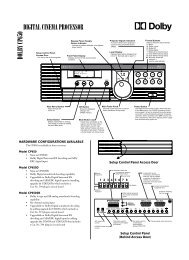
2.1.6 Toolbar<br />
The toolbar includes buttons <strong>for</strong> quick access to <strong>com</strong>monly used menu <strong>com</strong>mands, a<br />
master fader, and mute control. The toolbar is oriented vertically on the left edge of<br />
the window and contains buttons <strong>for</strong> the following <strong>com</strong>mands:<br />
New<br />
When a New file is requested, the current document is closed (a prompt appears to<br />
save the current document if it has been modified) and a new Untitled document with<br />
default settings is opened.<br />
Open<br />
Use the Open <strong>com</strong>mand to open an existing file from the PC file system. Cinema<br />
Processor files have the extension .dby. If a file is chosen, the current file is closed<br />
with a prompt to Save if modified.<br />
2-5
<strong>Dolby</strong> <strong>CP650</strong> <strong>Setup</strong> <strong>Software</strong><br />
<strong>Setup</strong> Window<br />
Save<br />
Save is enabled if the current document is modified. It saves the document, with its<br />
current settings, with the same name. In the case of an untitled document, the user is<br />
prompted <strong>for</strong> a file name. After per<strong>for</strong>ming a Save, the Save menu option is disabled,<br />
as the document is no longer modified.<br />
Connect/Disconnect<br />
Use the Connect <strong>com</strong>mand to establish a serial connection to the cinema processor. If<br />
successfully connected, follow the prompt to either Send or Retrieve settings as<br />
necessary. After connecting, this <strong>com</strong>mand changes to Disconnect.<br />
The Disconnect action severs the serial connection and restores the <strong>CP650</strong> to normal<br />
stand-alone operation. The <strong>Setup</strong> software does NOT prompt, save, exit, close, or<br />
otherwise alter the current parameter file when disconnecting. The Disconnect<br />
<strong>com</strong>mand then changes back to Connect. Upon disconnection, any changes made to<br />
the <strong>CP650</strong> settings are made part of the permanent Flash memory in the unit.<br />
Master Fader<br />
The function of the fader is to adjust the gain of the output according to the<br />
Fader Law shown in Figure 2-4. As the Fader increases from 0 to 4 in<br />
increments of 0.1, the gain increases from –90 dB to –10 dB. This translates<br />
to an increase of 20 dB per whole fader unit. As the fader increases from 4 to<br />
10 in increments of 0.1, the gain increases from –10 dB to 10 dB. This<br />
translates to an increase of 3 1/3 dB per fader unit. The fader level is<br />
displayed on the <strong>CP650</strong> front panel in a two-digit, seven-segment display.<br />
2-6
<strong>Dolby</strong> <strong>CP650</strong> <strong>Setup</strong> <strong>Software</strong><br />
<strong>Setup</strong> Window<br />
10<br />
0<br />
-10<br />
3 1/3 db<br />
per step<br />
-20<br />
-30<br />
Output<br />
Level (dB)<br />
-40<br />
20 dB<br />
per step<br />
-50<br />
-60<br />
-70<br />
-80<br />
-90<br />
0<br />
1<br />
2 3 4 5 6 7 8<br />
Fader Level<br />
9<br />
10<br />
Figure 2-4 Fader Law<br />
The master fader includes a fader level display, a slider to adjust the level, and a mute<br />
button that correspond directly to the analogous display and controls on the front<br />
panel of the cinema processor. The master fader is enabled whenever the <strong>Setup</strong><br />
software is connected, except when a tab is displayed which prescribes that the master<br />
fader be fixed at 7.0 (e.g., B-Chain EQ, Room Levels when Pink Noise is selected).<br />
Mute<br />
The Mute button controls the master mute function of the <strong>CP650</strong>. When the mute<br />
function has been activated, the Mute key on the <strong>CP650</strong> front panel flashes. When<br />
the unit is unmuted, the illumination extinguishes. The speed at which the<br />
mute/unmute functions occur are set with the Fade In Speed and Fade Out Speed<br />
control described in Section 2.12.1.<br />
2.1.7 Status Bar<br />
This area at the bottom of the main window displays help text <strong>for</strong> menu options, the<br />
current status of the signal source, and the cinema processor link status, Connected<br />
along with the baud rate, or Disconnected.<br />
2.2 Profile Tab<br />
This tab allows the user to enter identifying in<strong>for</strong>mation about the cinema processor,<br />
theatre, and settings file. When a new file is created (at startup or by using File→New),<br />
this be<strong>com</strong>es the top tab, and the cursor is set to the first field <strong>for</strong> data entry.<br />
2-7
<strong>Dolby</strong> <strong>CP650</strong> <strong>Setup</strong> <strong>Software</strong><br />
<strong>Setup</strong> Window<br />
The Profile tab should be used to record system configuration details. The in<strong>for</strong>mation<br />
entered, along with the setup parameters, can then be saved to a file and reloaded as<br />
needed.<br />
Figure 2-5 <strong>Setup</strong> Profile Tab<br />
2.2.1 Cinema Processor Serial Number<br />
Enter the serial number of the cinema processor to maintain a full record of the<br />
system setup.<br />
2.2.2 <strong>Dolby</strong> Digital Reader 1/2 Unit Serial Number<br />
Enter the digital reader serial numbers to maintain a full record of the system setup.<br />
2.2.3 Cinema Processor Firmware Version Number<br />
In<strong>for</strong>mation about the cinema processor is sent from the <strong>CP650</strong> to the PC when a<br />
connection is made. The Firmware Version Number, DSP Version Number,<br />
Option Card, and Ethernet address are then be displayed.<br />
2.2.4 Cinema Processor DSP Version Number<br />
The <strong>CP650</strong> module version string is sent from the <strong>CP650</strong> to the PC when a<br />
connection is made.<br />
2.2.5 Cinema Processor Option Card<br />
In<strong>for</strong>mation about installed option cards is sent from the <strong>CP650</strong> to the PC when a<br />
connection is made.<br />
2-8
<strong>Dolby</strong> <strong>CP650</strong> <strong>Setup</strong> <strong>Software</strong><br />
<strong>Setup</strong> Window<br />
2.2.6 <strong>CP650</strong> Ethernet Address<br />
The Ethernet address of the cinema processor is read by the PC and displayed on this tab.<br />
2.2.7 Additional Fields<br />
Enter data <strong>for</strong> the remaining fields as desired: Project Name, Theatre Name, Screen<br />
Number, Projector Model Number, Automation System, and Comments. These<br />
entries, along with cinema processor serial number (see 2.2.1 above) and reader serial<br />
number (see 2.2.2 above) are saved to the .dby file on disk.<br />
2.3 Optical Tab<br />
This tab is used to configure the optical settings in the cinema processor, including<br />
level and slit-loss equalization. When the Optical tab is selected, the <strong>for</strong>mat<br />
automatically changes to allow the appropriate adjustments. Optical adjustments<br />
require the use of Cat. No. 69T and Cat. No. 69P test films.<br />
Figure 2-6 <strong>Setup</strong> Optical Tab<br />
2.3.1 Projector 1/2<br />
Click on Projector 1 or Projector 2 to begin adjustment of projector one or two.<br />
2.3.2 Lt Level and Rt Level Adjustments<br />
While running Cat. No. 69T, <strong>Dolby</strong> Tone Test Film, Lt and Rt levels may be adjusted<br />
individually using the associated slider until both green elements are illuminated. This<br />
ensures the correct input level to the <strong>CP650</strong>. Alternately, click Auto Level to allow<br />
the <strong>CP650</strong> to per<strong>for</strong>m the adjustment.<br />
2-9
<strong>Dolby</strong> <strong>CP650</strong> <strong>Setup</strong> <strong>Software</strong><br />
<strong>Setup</strong> Window<br />
2.3.3 Auto Level<br />
Click Auto Level to allow the <strong>CP650</strong> to automatically adjust the Lt and Rt preamp<br />
gain levels.<br />
Figure 2-7 Auto Level in Progress; Adjustment Complete; Level Out of Range<br />
2.3.4 Slit-Loss EQ<br />
The Slit-Loss EQ is an equalization curve that <strong>com</strong>pensates <strong>for</strong> optical deficiencies<br />
resulting from slit-height variations. The curve provides a unique high-frequency<br />
boost that <strong>com</strong>pensates <strong>for</strong> these variations. The level of correction necessary varies<br />
by reader type. Typically, reverse-scan basement readers require less adjustment than<br />
<strong>for</strong>ward-scan readers.<br />
2.3.5 Left/Right<br />
Adjust the Left and Right Slit-Loss EQ <strong>for</strong> the most extended high-frequency<br />
response without <strong>for</strong>ming a peak. (Click the Left or Right slider to activate the<br />
spectrum analyzer display.)<br />
2.3.6 Auto EQ<br />
Alternately, click Auto EQ to allow the <strong>CP650</strong> to per<strong>for</strong>m the adjustment. A<br />
dramatic difference in the Left and Right levels may indicate an optical problem.<br />
2.4 Room Levels Tab<br />
The current signal selection (Pink Noise, Program, 100 Hz, etc.) is maintained<br />
between pages that support the Pink Noise option (B-Chain EQ, Room Levels, and<br />
Subwoofer EQ). Switching the signal mode to Pink Noise clears all the channels.<br />
With Pink Noise on, all channels are mutually exclusive—selecting any one clears<br />
any other selection. To select multiple surround channels, hold the Control key down<br />
while making selections. The subwoofer channel is independent in all cases.<br />
2-10
<strong>Dolby</strong> <strong>CP650</strong> <strong>Setup</strong> <strong>Software</strong><br />
<strong>Setup</strong> Window<br />
Figure 2-8 <strong>Setup</strong> Room Levels Tab<br />
2.4.1 Surrounds<br />
Surrounds define the configuration of the surround channels <strong>for</strong> output-level adjust<br />
and B-Chain EQ. If operating disconnected, the interface provides two options <strong>for</strong><br />
surround configuration. If connected and a Surround EX adapter card is installed in<br />
the <strong>CP650</strong>, the selection is <strong>for</strong>ced to Surround EX and the button is disabled. If no<br />
Surround EX card is installed, the Surround EX button choice is not available.<br />
Conventional 5.1<br />
This is the default setting. <strong>Dolby</strong> Digital utilizes discrete left and right surround<br />
channels. During optical film playback, both Ls and Rs are fed an identical mono<br />
surround signal.<br />
Surround EX<br />
Surround EX includes channels Ls, Bsl (back surround left), Bsr (back surround<br />
right), and Rs.<br />
2.4.2 SPL Meter<br />
The Internal SPL meter can be used to set room levels of each channel, if calibrated.<br />
The microphone is connected through either the rear XLR connector or the front Mic<br />
Mux connector.<br />
Figure 2-9 Internal SPL Meter<br />
2-11
<strong>Dolby</strong> <strong>CP650</strong> <strong>Setup</strong> <strong>Software</strong><br />
<strong>Setup</strong> Window<br />
2.4.3 Internal Calibration<br />
Click Calibrate Internal Meter to enable microphone calibration. Pink Noise is then<br />
routed through the center channel. While using an external SPL meter in close proximity<br />
to the microphone, dial in the SPL reading to match what is detected in the theatre. Click<br />
Calibrate to calibrate the <strong>CP650</strong> and the microphone to the SPL reading. If an error<br />
message occurs, indicating the microphone level is too low or too high, check your<br />
connections, phantom power, and mic level trimpot located on the front panel of the<br />
<strong>CP650</strong>.<br />
Figure 2-10 Error Message <strong>for</strong> Failed Calibration<br />
2.4.4 Output Level Adjust<br />
This group provides checkbox, label, static value display, and slider controls <strong>for</strong> each<br />
channel as determined by the current Surround configuration. The value always<br />
displays the current channel slider setting which, when connected, always matches<br />
the setting currently in use in the cinema processor. When leaving the Room Levels<br />
page, all channels are activated.<br />
Subwoofer Level<br />
Clicking this button brings up the Subwoofer Level dialog box. This window provides<br />
<strong>for</strong> level trim of the two subwoofer modes, optical and digital. Checkboxes are<br />
provided to turn Center Noise and Reverse Sub Polarity on and off when Optical<br />
Level is selected; these checkboxes are disabled when Digital Level is selected.<br />
Note: The reference values are not displayed on the Subwoofer spectrum analyzer<br />
until the microphone is calibrated.<br />
Figure 2-11 Subwoofer Level<br />
2-12
<strong>Dolby</strong> <strong>CP650</strong> <strong>Setup</strong> <strong>Software</strong><br />
<strong>Setup</strong> Window<br />
The initial level setting <strong>for</strong> the digital subwoofer is 1. The optical subwoofer level is<br />
relative to the digital level. If making adjustments to one, check the other.<br />
Center Noise and Reverse Sub Polarity are only available when adjusting the<br />
Optical Subwoofer Level.<br />
The Center Noise checkbox corresponds to the Center channel checkbox on the<br />
Room Levels tab. It is initially selected if the Center channel checkbox was selected<br />
on the Room Levels tab. If using the <strong>Setup</strong> analyzer, Center Noise should <strong>com</strong>e up<br />
to the 0 dB line. Digital subwoofer level should be trimmed to +10 dB, while the<br />
optical subwoofer level should be trimmed to 0 dB.<br />
The Reverse Sub Polarity checkbox is initially clear. It is used to check <strong>for</strong><br />
subwoofer center channel phase matching. With Optical Level and Center Noise<br />
selected, there should be some adding of the lower frequencies; with Reverse Sub<br />
Polarity selected, there should be some noticeable subtraction of lower frequencies.<br />
If the Reverse Sub Polarity checkbox is set when leaving the Subwoofer Level<br />
window, a warning message to verify speaker connections is displayed and the<br />
polarity returned to normal.<br />
2.4.5 Signal<br />
Signal Generator<br />
The Signal Generator selection is maintained between pages that support the Pink<br />
Noise option (B-Chain EQ, Room Levels, and Subwoofer EQ).<br />
Pink Noise<br />
<strong>Dolby</strong> Level pink noise is used when this is selected. Initial selection of this option<br />
clears all output channels. The user must then manually select to which channels to<br />
apply the noise. If Pink Noise is selected when switching to a setup tab other than B-<br />
Chain EQ or Subwoofer EQ, the noise is turned off, and the signal output is returned<br />
to the global signal generator setting.<br />
2.4.6 Bypass<br />
Pressing the Bypass Level button invokes the Bypass Level Adjust window. This<br />
places the <strong>CP650</strong> in Format 05. Clicking the Bypass On checkbox switches the<br />
<strong>CP650</strong> into Bypass mode. Adjust the Bypass Level trimpot to match the SPL of the<br />
same film in Format 05.<br />
2-13
<strong>Dolby</strong> <strong>CP650</strong> <strong>Setup</strong> <strong>Software</strong><br />
<strong>Setup</strong> Window<br />
Figure 2-12 Bypass Level Adjust<br />
2.5 B-Chain EQ Tab<br />
The B-Chain EQ tab is used to adjust each channel’s frequency response to achieve<br />
the desired response curve. This is achieved by using a <strong>com</strong>bination of bulk and onethird<br />
octave EQ.<br />
Figure 2-13 <strong>Setup</strong> B-Chain EQ Tab<br />
2.5.1 Channels<br />
The current channel name appears at the top of the B-Chain EQ tab, as selected at<br />
the bottom of the tab. The solid line on the graph represents the standard ISO 2969<br />
curve. When one of the frequency sliders is selected, the corresponding line segment<br />
is yellow. The slider can then be adjusted <strong>for</strong> boost or cut.<br />
With the cursor anywhere on the B-Chain EQ tab, click the right mouse button to<br />
display Copy and Paste functions. These may be used to copy frequency settings from<br />
one channel to another.<br />
2-14
<strong>Dolby</strong> <strong>CP650</strong> <strong>Setup</strong> <strong>Software</strong><br />
<strong>Setup</strong> Window<br />
2.5.2 EQ Assist<br />
Use this button to apply an approximation algorithm to bring the EQ <strong>for</strong> the channel<br />
close to the desired response curve. Bulk EQ as well as amplifier gains should<br />
always be adjusted be<strong>for</strong>e applying EQ Assist. EQ Assist is only enabled if the Internal<br />
SPL Meter has been calibrated on the Room Levels screen and Pink Noise is<br />
activated.<br />
2.5.3 Flatten EQ<br />
Click Flatten EQ to return all frequency bands and Bulk EQ to zero. A prompt<br />
appears <strong>for</strong> confirmation.<br />
2.5.4 Bulk EQ<br />
Bulk EQ is used to adjust the bulk equalizers. It is important to adjust both the Bass<br />
and the Treble EQ prior to adjusting the individual one-third-octave bands.<br />
Bass Level<br />
The Bass Level is adjustable from –6 to +6 dB in 0.2 dB steps. Use the slider to make<br />
adjustments to match the reference curve.<br />
Treble Level<br />
The Treble Level is adjustable from –10 to +10 dB in 0.2 dB steps.<br />
Treble Freq<br />
The treble corner frequency can be 1, 2, 3, or 4 kHz, and only applies to the Left,<br />
Center, and Right channels. Adjust to match the reference curve as closely as<br />
possible. (The corner frequency is fixed at 2 kHz <strong>for</strong> the surround channels.)<br />
2.5.5 Channel Level<br />
This slider may be used to adjust the output level of the currently selected channel<br />
and is reflected on the Room Levels tab. This does not affect the overall level seen on<br />
the spectrum analyzer because the average of frequency bands 7 through 20 is always<br />
placed at 0 dB.<br />
2.5.6 Signal Generator/Pink Noise<br />
Buttons are provided to select the signal source as Signal Generator or Pink Noise.<br />
The spectrum analyzer is only active when Pink Noise is selected.<br />
2-15
<strong>Dolby</strong> <strong>CP650</strong> <strong>Setup</strong> <strong>Software</strong><br />
<strong>Setup</strong> Window<br />
2.6 Subwoofer EQ Tab<br />
This screen in used to adjust the subwoofer’s parametric equalizer. The three<br />
parameters that define the equalizer are Frequency, Q, and Cut. Identify a frequency<br />
region that may contain a peak and adjust the parametric equalizer to obtain a flatter<br />
response. Note that the vertical axis will be unlabeled if the Internal SPL Meter was<br />
not calibrated from the Room Levels tab.<br />
Figure 2-14 <strong>Setup</strong> Subwoofer EQ Tab<br />
2.6.1 Frequency<br />
The filter’s center Frequency is adjustable from 25 to 125 Hz. The approximate<br />
corresponding band is highlighted on the real-time analyzer.<br />
2.6.2 Q<br />
The Q defines the width of the Cut band. The Q settings are 0.5, 1, 2, and 4.<br />
2.6.3 Cut<br />
The Cut value is applied to the center Frequency as selected above, reducing the<br />
output level in the Q region. The cut amount is adjustable between 0 and –12.0 dB in<br />
0.2 dB steps.<br />
2.6.4 Graph<br />
When Pink Noise is activated, the graph displays the subwoofer frequency response.<br />
With 0.0 dB of Cut, identify the frequency region with the tallest bump. Adjust<br />
Frequency, Q, and Cut to achieve the flattest frequency response.<br />
2-16
<strong>Dolby</strong> <strong>CP650</strong> <strong>Setup</strong> <strong>Software</strong><br />
<strong>Setup</strong> Window<br />
2.6.5 Signal Generator/Pink Noise<br />
Buttons are provided to select the signal source as Signal Generator or Pink Noise.<br />
2.7 Mono Tab<br />
Selecting the Mono tab sets the <strong>CP650</strong> to Format 01. The functions on this tab apply<br />
to the Center channel while in Format 01.<br />
Figure 2-15 <strong>Setup</strong> Mono Tab<br />
2.7.1 Mono Level Trim<br />
Mono Level Trim adjustment can vary between –12 dB and 0 dB in 0.2 dB steps.<br />
This trim is an offset from the normal playback level.<br />
2.7.2 Mono EQ<br />
While monitoring film program material, adjust Mono EQ <strong>for</strong> preferred audio tonal<br />
quality. There are 16 steps between the low-frequency and high-frequency settings <strong>for</strong><br />
the Mono EQ.<br />
2.8 Misc Levels Tab<br />
The Misc Levels tab provides sliders <strong>for</strong> adjusting the Optical Surround Level<br />
Trim and Nonsync 1 and 2 levels.<br />
2-17
<strong>Dolby</strong> <strong>CP650</strong> <strong>Setup</strong> <strong>Software</strong><br />
<strong>Setup</strong> Window<br />
Figure 2-16 <strong>Setup</strong> Miscellaneous Levels Tab<br />
2.8.1 Opt. Surr. Level Trim<br />
The Optical Surround Level Trim is adjustable from –3 dB to +6 dB in 0.2 dB<br />
steps. This applies to optical surround playback.<br />
2.8.2 Nonsync 1 and 2 Level<br />
The Nonsync 1 and 2 adjustments are controlled by sliders. The number is unitless,<br />
and ranges from 1 to 127.<br />
2.9 Delays Tab<br />
The Optical Surround Delay should be adjusted so that sounds from the rear of the<br />
theatre (surround channels) arrive at the listener’s ear approximately 20 ms after the<br />
arrival of sound from the screen speakers.<br />
The Digital Surround Delay should be adjusted so that sounds from the rear of the<br />
theatre arrive at the listener’s ear at the same time as the screen speakers.<br />
2-18
<strong>Dolby</strong> <strong>CP650</strong> <strong>Setup</strong> <strong>Software</strong><br />
<strong>Setup</strong> Window<br />
Figure 2-17 <strong>Setup</strong> Delays Tab<br />
2.9.1 Surround Delay<br />
Optical<br />
The Optical Surround Delay is adjustable from 20 to 150 ms in 1 ms steps. When<br />
the Optical delay level is set manually, the Digital delay automatically changes to the<br />
same level minus 20 ms, but can be adjusted separately.<br />
Digital<br />
The Digital Surround Delay is adjustable from 20 to 150 milliseconds in 1 ms steps.<br />
2.9.2 Delay Calculation<br />
The <strong>Setup</strong> program can calculate and set both Optical and Digital Surround Delay<br />
values based on theatre measurements entered here.<br />
Feet/Meters<br />
Measurements may be made in Feet or Meters. Select the desired units.<br />
Distance from screen to rear wall of theatre<br />
Values must be between 10 and 200, Feet or Meters.<br />
Average distance between left and right surround channels<br />
Values must be between 10 and 140, Feet or Meters.<br />
Calculate<br />
Click Calculate to calculate and automatically set the Surround Delay.<br />
2-19
<strong>Dolby</strong> <strong>CP650</strong> <strong>Setup</strong> <strong>Software</strong><br />
<strong>Setup</strong> Window<br />
2.10 <strong>Dolby</strong> Digital Tab<br />
Selecting the <strong>Dolby</strong> Digital tab automatically sets the <strong>CP650</strong> to Format 10, <strong>Dolby</strong><br />
Digital.<br />
Figure 2-18 <strong>Setup</strong> <strong>Dolby</strong> Digital Tab<br />
2.10.1 Reader Delay<br />
Reader Delay adjustment is used to synchronize the digital soundtrack with the<br />
analog track and the picture. It can be set by selecting the reader model or by<br />
manually adjusting the number of per<strong>for</strong>ations when using the Cat. No. 1010 Sync<br />
Test Film.<br />
Select <strong>Dolby</strong> Digital Reader Model<br />
The specific reader model selection is shown in Table 2-1. Selecting a reader model<br />
provides an approximation of the correct reader delay. Adjust the delay using the Cat.<br />
No. 1010 Sync Test Film.<br />
2-20
<strong>Dolby</strong> <strong>CP650</strong> <strong>Setup</strong> <strong>Software</strong><br />
<strong>Setup</strong> Window<br />
Table 2-1 <strong>Dolby</strong> Digital Reader Models<br />
Reader Model<br />
Per<strong>for</strong>ations<br />
Other (default) 20<br />
<strong>Dolby</strong> Cat. No. 699/700/701 250<br />
Ballantyne 35 penthouse 247<br />
Century Projector with Component Engineering or Kelmar basement 20<br />
Century 35 mm (SA) penthouse 245<br />
Century 35/70 (JJ) penthouse 309<br />
Christie basement 26<br />
Christie penthouse 250<br />
Cinemeccanica V5 basement 28<br />
Cinemeccanica V5 penthouse 252<br />
Cinemaccanica V8 penthouse 260<br />
Ernemann 15 30<br />
Kinoton FP30 21<br />
Norelco/Kinoton AAll (DP70) penthouse 283<br />
Simplex with Component Engineering or Kelmar basement 26<br />
Simplex 35 mm (XL) penthouse 242<br />
Simplex 35/70 penthouse 298<br />
Per<strong>for</strong>ations<br />
The number of Per<strong>for</strong>ations to delay can be set from 16 to 512 using the up and<br />
down arrows. When a reader is selected, as described above, the number of<br />
per<strong>for</strong>ations changes accordingly.<br />
2.10.2 Auto <strong>Dolby</strong> Digital<br />
If <strong>Dolby</strong> Digital is playing and another film <strong>for</strong>mat is selected, the <strong>CP650</strong> goes into<br />
the selected <strong>for</strong>mat, and auto digital is temporarily disabled. Auto Digital is reenabled<br />
when a non-film <strong>for</strong>mat is asserted and then a film <strong>for</strong>mat is asserted. At that<br />
time the system is ready to automatically go into the target <strong>for</strong>mat when <strong>Dolby</strong><br />
Digital audio appears.<br />
Auto Digital Target<br />
The Auto Digital Target may be <strong>for</strong>mat 10, or <strong>for</strong>mat 13 if a Surround EX card is<br />
installed.<br />
2-21
<strong>Dolby</strong> <strong>CP650</strong> <strong>Setup</strong> <strong>Software</strong><br />
<strong>Setup</strong> Window<br />
2.10.3 Reversion Mode<br />
Figure 2-19 No Reversion Warning<br />
With Reversion Mode set to Normal, the audio may revert to the analog soundtrack<br />
if necessary. A setting of No Reversion keeps the <strong>CP650</strong> in the target <strong>for</strong>mat<br />
regardless of the condition of the <strong>Dolby</strong> Digital data.<br />
2.10.4 Auto Surround EX<br />
The <strong>CP650</strong> automatically switches to Surround EX mode when all the following<br />
conditions are met:<br />
• A Surround EX option board is installed.<br />
• Format 10 is asserted.<br />
• Surround EX is present within the <strong>Dolby</strong> Digital data.<br />
• Auto Surround EX is enabled.<br />
Figure 2-20 Auto Surround EX Warning<br />
2.11 Formats Tab<br />
Use the Formats tab to enable and assign Preset Fader Settings, User Formats, and<br />
to select the Power-on Format.<br />
2-22
<strong>Dolby</strong> <strong>CP650</strong> <strong>Setup</strong> <strong>Software</strong><br />
<strong>Setup</strong> Window<br />
Figure 2-21 <strong>Setup</strong> <strong>Dolby</strong> Digital Tab<br />
2.11.1 Enable Preset Fader Setting<br />
Click on a box to enable the Preset Fader. Use the up and down arrows to modify the<br />
Fader Setting between 0.0 and 10.0. The default Fader Setting is 7.0.<br />
User 1, User 2, and Nonsync<br />
User 1, User 2, and Nonsync may be set to any of the <strong>for</strong>mats listed in Table 2-2.<br />
Table 2-2 User Formats<br />
Number Format Number Format<br />
01 Mono 65 Public Address Surround Channels<br />
04 <strong>Dolby</strong> A-type 66 Test Tone 320 Hz<br />
05 <strong>Dolby</strong> SR 70 Video PA (NS1)<br />
10 <strong>Dolby</strong> Digital 71 Video Mono (NS1)<br />
11 External 6-Channel 73 Video LCR (NS1)<br />
13 <strong>Dolby</strong> Digital Surround EX 74 Video Pro Logic no Subwoofer (NS1)<br />
20 35 mm Magnetic, 3-Channel 75 Video Pro Logic with Subwoofer (NS1)<br />
22 35 mm Magnetic, 4-Channel 80 Digital Input<br />
42 70 mm <strong>Dolby</strong> Stereo 81 External <strong>Dolby</strong> Digital Surround EX<br />
60 Nonsync 1 87 External 6-Channel with Surround EX<br />
61 Nonsync 2 92 <strong>Dolby</strong> SR (6-Channel In)<br />
64 Public Address Center Channel 93 <strong>Dolby</strong> SR (NS1)<br />
2.11.2 Power-On Format<br />
Select the audio <strong>for</strong>mat <strong>for</strong> the <strong>CP650</strong> when power is turned on.<br />
2-23
<strong>Dolby</strong> <strong>CP650</strong> <strong>Setup</strong> <strong>Software</strong><br />
<strong>Setup</strong> Window<br />
Table 2-3 Power On Formats<br />
Power On Formats<br />
Last Format<br />
Format 01<br />
Format 04<br />
Format 05<br />
Format 10<br />
Format 11<br />
User 1<br />
User 2<br />
Nonsync<br />
2.12 Misc. Tab<br />
Figure 2-22 <strong>Setup</strong> Miscellaneous Tab<br />
2.12.1 Mute<br />
The length of time <strong>for</strong> sound to fade from normal to mute, when Mute is selected, is<br />
the Fade Out Speed. The time to return from muted to normal is the Fade In Speed.<br />
Both are adjustable from 0.2 to 5.0 seconds in 0.1-second intervals using the<br />
appropriate slider.<br />
2.12.2 Clock<br />
The current PC time and date are displayed. Use the Set <strong>CP650</strong> Clock button to<br />
synchronize the <strong>CP650</strong> clock to the PC time.<br />
2-24
<strong>Dolby</strong> <strong>CP650</strong> <strong>Setup</strong> <strong>Software</strong><br />
<strong>Setup</strong> Window<br />
2.12.3 Noise Gating<br />
Pressing this button puts the <strong>CP650</strong> into noise gate mode. Click OK to exit the noise<br />
gate mode. When in noise gating mode, an automation line controls an internal pink<br />
noise source. Pink noise is activated by shorting the automation line-associated pin to<br />
ground (pin 12); pin numbers 1 through 8 represent L, C, R, Ls, Rs, SW, all, and Bs<br />
channels, respectively.<br />
2.12.4 Rotating Noise<br />
When Rotating Noise is selected, a five-second pink noise signal is sent to each speaker<br />
sequentially. The channel currently running pink noise is indicated in the display.<br />
Click Pause to halt the pink noise to the current channel; click Done to exit from the<br />
Rotating Noise test.<br />
Figure 2-23 Rotating Noise<br />
Caution: The rotating pink noise is set to 85 dB <strong>for</strong> all channels during this test.<br />
2.13 Spectrum Analyzer Tab<br />
The Spectrum Analyzer tab displays the frequency response of the selected audio<br />
input. When the tab is selected, the default <strong>for</strong>mat is Nonsync 1. Only one channel<br />
may be selected at a time.<br />
2-25
<strong>Dolby</strong> <strong>CP650</strong> <strong>Setup</strong> <strong>Software</strong><br />
<strong>Setup</strong> Window<br />
Figure 2-24 <strong>Setup</strong> Spectrum Analyzer<br />
2-26
<strong>Dolby</strong> <strong>CP650</strong> <strong>Setup</strong> <strong>Software</strong><br />
Chapter 3<br />
Event Log<br />
Choosing the Event Log from the Window menu brings up the Event Log window.<br />
The Event Log immediately receives and displays the current event log in<strong>for</strong>mation<br />
from the <strong>CP650</strong>. This log includes a date/time stamp, summary, and description <strong>for</strong><br />
each event.<br />
The Event Log window provides options <strong>for</strong> printing the Event Log and saving the<br />
Event Log as text. An example is shown below.<br />
Cinema Processor Event Log<br />
File C:\My Documents\<strong>CP650</strong>\Event Logs\ken's unit.txt<br />
Date 12Mar2001<br />
Time 14:05:30<br />
System version 1.2.1.4<br />
<strong>Setup</strong> version 1.2.1.3 Beta<br />
Cinema Processor Option Card: Cat. No. 773 / Cat. No. 794<br />
Cinema Processor DSP Version Number: 020203030403030202<br />
Cinema Processor Ethernet Address: 00 D0 46 00 00 2E<br />
Time Summary Description<br />
---- ------- -----------<br />
13-JAN-00 00:34:07 Startup<br />
12-MAR-01 13:37:37 Startup<br />
12-MAR-01 13:38:41 Startup<br />
Figure 3-1 Event Log Example<br />
3-1
<strong>Dolby</strong> DMU AD/DA Converter<br />
3-1