csi-thermal program installation inspection checklist failure items
csi-thermal program installation inspection checklist failure items
csi-thermal program installation inspection checklist failure items

Create successful ePaper yourself
Turn your PDF publications into a flip-book with our unique Google optimized e-Paper software.
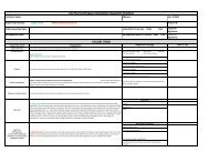
CSI-THERMAL PROGRAM INSTALLATION INSPECTION CHECKLIST<br />
Name:<br />
Address:<br />
Date:<br />
SRCC #:<br />
Back-Up Fuel Source (Gas or Electric):<br />
Inspector:<br />
CSI-Thermal Program Inspection Checklist is based on the Solar Rating and Certification (SRCC) Operating Guidelines (OG) 300, as referenced in column A. The SRCC comments are noted in<br />
the explanation column using this same font. Comments written in Italics represent explanations from the CSI-Thermal Program Administrators.<br />
FAILURE ITEMS<br />
SRCC # Inspection Item Explanation Inspection Findings: Pass or Fail<br />
(Explanation required for <strong>failure</strong>)<br />
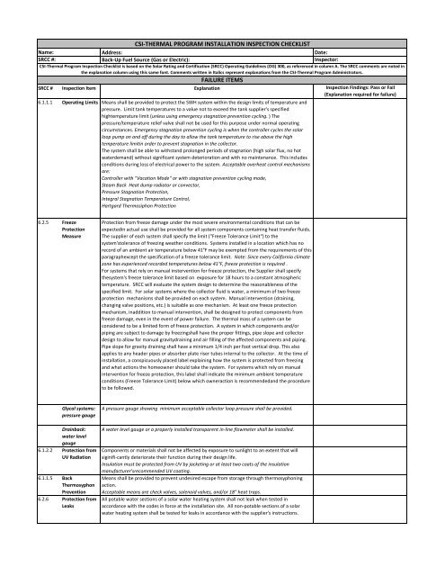
6.1.1.1 Operating Limits Means shall be provided to protect the SWH system within the design limits of temperature and<br />
pressure. Limit tank temperatures to a value not to exceed the tank supplier's specified<br />
hightemperature limit (unless using emergency stagnation prevention cycling. ) The<br />
pressure/temperature relief valve shall not be used for this purpose under normal operating<br />
circumstances. Emergency stagnation prevention cycling is when the controller cycles the solar<br />
loop pump on and off during the day to allow the tank temperature to rise above the high<br />
temperature limitin order to prevent stagnation in the collector.<br />
The system shall be able to withstand prolonged periods of stagnation (high solar flux, no hot<br />
waterdemand) without significant system deterioration and with no maintenance. This includes<br />
conditions during loss of electrical power to the system. Acceptable overheat control mechanisms<br />
are:<br />
Controller with "Vacation Mode" or with stagnation prevention cycling mode,<br />
Steam Back Heat dump radiator or convector,<br />
Pressure Stagnation Protection,<br />
Integral Stagnation Temperature Control,<br />
Hartgard Thermosiphon Protection<br />
6.2.5 Freeze<br />
Protection<br />
Measure<br />
Protection from freeze damage under the most severe environmental conditions that can be<br />
expectedin actual use shall be provided for all system components containing heat transfer fluids.<br />
The supplier of each system shall specify the limit ("Freeze Tolerance Limit") to the<br />
system'stolerance of freezing weather conditions. Systems installed in a location which has no<br />
record of an ambient air temperature below 41°F may be exempted from the requirements of this<br />
paragraphexcept the specification of a freeze tolerance limit. Note: Since every California climate<br />
zone has experienced recorded temperatures below 41°F, freeze protection is required .<br />
For systems that rely on manual instervention for freeze protection, the Supplier shall specify<br />
thesystem's freeze tolerance limit based on exposure for 18 hours to a constant atmospheric<br />
temperature. SRCC will evaluate the system design to determine the reasonableness of the<br />
specified limit. For solar systems where the collector fluid is water, a minimum of two freeze<br />
protection mechanisms shall be provided on each system. Manual intervention (draining,<br />
changing valve positions, etc.) is suitable as one mechanism. At least one freeze protection<br />
mechanism, inaddition to manual intervention, shall be designed to protect components from<br />
freeze damage, even in the event of power <strong>failure</strong>. The <strong>thermal</strong> mass of a system can be<br />
considered to be a limited form of freeze protection. A system in which components and/or<br />
piping are subject to damage by freezingshall have the proper fittings, pipe slope and collector<br />
design to allow for manual gravitydraining and air filling of the affected components and piping.<br />
Pipe slope for gravity draining shall have a minimum 1/4 inch per foot vertical drop. This also<br />
applies to any header pipes or absorber plate riser tubes internal to the collector. At the time of<br />
<strong>installation</strong>, a conspicuously placed label explaining how the system is protected from freezing<br />
and what actions the homeowner should take the system. For systems which rely on manual<br />
intervention for freeze protection, this label shall indicate the minimum ambient temperature<br />
conditions (Freeze Tolerance Limit) below which owneraction is recommendedand the procedure<br />
to be followed.<br />
Glycol systems:<br />
pressure gauge<br />
Drainback:<br />
water level<br />
gauge<br />
6.1.2.2 Protection from<br />
UV Radiation<br />
6.1.1.5 Back<br />
Thermosyphon<br />
Prevention<br />
6.2.6 Protection from<br />
Leaks<br />
A pressure gauge showing minimum acceptable collector loop pressure shall be provided.<br />
A water level gauge or a properly installed transparent in-line flowmeter shall be installed.<br />
Components or materials shall not be affected by exposure to sunlight to an extent that will<br />
siginifi-cantly deteriorate their function during their design life.<br />
Insulation must be protected from UV by jacketing or at least two coats of the insulation<br />
manufacturer'srecommended UV coating.<br />
Means shall be provided to prevent undesired escape from storage through thermosyphoning<br />
action.<br />
Acceptable means are check valves, solenoid valves, and/or 18" heat traps.<br />
All potable water sections of a solar water heating system shall not leak when tested in<br />
accordance with the codes in force at the <strong>installation</strong> site. All non-potable sections of a solar<br />
water heating system shall be tested for leaks in accordance with the supplier's instructions.
6.1.2 Collector The collector model and size must be consistent with the Claim Form and with SRCC label.<br />
Number of Collectors:<br />
Manufacturer:<br />
Model:<br />
True Azimuth:<br />
Tilt:<br />
Shade<br />
No more than 15% annual shading is allowed on the solar collectors between the hours of 10am<br />
and 3pm. Shading %:<br />
6.1.2.4 Collector Flow<br />
Rate<br />
In multiple collectors arrays the instantaneous flow rate variation between collectors shall not<br />
exceed10% of the array average flow. When an array of collectors is connected by manifolds to<br />
form a parallelflow configuration, provision shall be incorporated in the manifold and/or<br />
collectors to maintain the proper design flow rate of the heat transfer fluid through each<br />
collector.<br />
6.5.6 Water Damage Collectors and support shall be installed in such a manner that water flowing off the collector<br />
surface or from the pressure relief valve shall not damage the building or cause premature<br />
erosion of the roof. Water tanks located in or above the living space shall be installed on a drip<br />
pan with a drain line to a waste or outside or have other means to safely remove any excess<br />
liquid.<br />
6.1.3.1 Solar Tank Both pressurized and non-pressurized tanks shall meet the requirements set by a nationally<br />
accepted standard setting organization. Non-pressurized tanks shall be vented to atmospheric<br />
pressure. Non-fiberglas hot water storage tanks shall comply with ASME Boiler and Pressure<br />
vessel Code, Division 1, Section vii, "Rules for Construction of Pressure Vessels" unless they fall<br />
into one of the classes of vessels exempted in Part u-1c. Fiber-reinforced plastic pressure vessels<br />
shall comply with ASME Boiler and Pressure Vessel Code, Section X, "Fiber-Reinforced Plastic<br />
Pressure Vessels" unless they fall into one of the classes of vessels exempted in Part RG-121. Gas<br />
water heaters shall comply with ANSI Z21.10.1-2004?CSA 4.1-2004 'Gas Water Heaters Volume 1,<br />
Storage Water Heaters With Input21.10.3 -2004?CSA 4.3_2004' Gas Water Heaters - Volume III,<br />
Volume 111, Storage Water Heaters withInput Ratings Above 75,000 Btu per hour, Circulating and<br />
Instantaneous'.<br />
6.1.3.3 Waterproofing Underground and above ground unsheltered storage tanks shall be waterproofed to prevent<br />
water seepage. Storage tanks used outdoors shall be rated for outdoor use.<br />
6.1.2.7 Collectror<br />
Circulation<br />
Control<br />
The collector subsystem control shall be designed to be compatible with control requirements of<br />
the system.<br />
6.1.5.5 &<br />
6.5.18<br />
Control Line and<br />
Sensors<br />
All wires and connections, sensors, pneumatic lines, hydraulic lines or other means for<br />
transmittingsensor outputs to control devices shall be sufficiently protected from degradation or<br />
from introducing false signals as a result of environmental influence such as wind, moisture,<br />
temperature or otherfactors which may alter their intended sensing function. Weather-exposed<br />
wiring must be rated sunlight and moisture resistant and comply with NEC Articles 340 and 690.<br />
Sensor wiring shall be separated from hot collector piping and shall be protected from UV.<br />
Capacity:<br />
Manufacturer:<br />
Model:<br />
6.1.5.6 Temperature<br />
Control/Mixing<br />
Valve<br />
The system shall be equipped with a mixing valve to limit scalding temperature water to the endusers.<br />
Acceptable means are:<br />
Properly installed mixing valves or ASSE anti-scald valves with a setpoint optin appropriate for use.<br />
Other ASSE rated anti-scald valves such as point-of-use anti-scald valves<br />
6.1.6.3 Insulation All interconnecting hot water piping and the final 5 feet of metallic cold water supply pipe leading<br />
tothe system, or the length of piping which is accessible if less than 5 feet, shall be insulated<br />
withR-2.6 °F-ft2-hr/Btu or greater insulation. All exterior piping insulation shall be at least 3/4"<br />
thick wall , rated for the temperatures expected, and protected from UV or moisture<br />
damage.Systems with recirculation loops must insulate all accessible piping with a minimum of<br />
R2.6 value insulation. This includes the hot supply line from the auxiliary water heater to the<br />
farthest accessible point of use and the return line from the farthest accessible point of use back<br />
to the auxiliary water heater.
6.6.1 Owner's Manual An owner's manual or manuals shall be provided with each SWH system. The manual shall<br />
containthe name, phone number and address of the system supplier, the system model name or<br />
numberand shall describe the operation of the system and its components and the procedures for<br />
<strong>installation</strong>,operation and maintenance.<br />
Manuals for OG-300 systems shall be approved by the SRCC for content as described in Sections<br />
6.6.2to 6.6.7. This approval shall be indicated on the manuals as follows: "The solar energy<br />
system described by this manual, when properly installed and maintained, meets the minimum<br />
standards established by the SRCC. This certification does not imply endorsement or warranty of<br />
this product by SRCC." The manual shall include a comprehensive plan for maintaining the<br />
specified performanceof the SWH system. The plan shall include a schedule and description of<br />
procedures for ordinary and preventive maintenance including cleaning of collector exterior<br />
surfaces. The manual shall include minor repairs and give the projections for equipment<br />
replacement.Multifamily and Commercial systems using OG-100 collectors must also have an<br />
owner's manual, provided by either the manufacturer or solar contractor.<br />
INFRACTIONS<br />
SRCC # Inspection Item Explanation Inspection Findings<br />
ICS Owner's<br />
Manual<br />
An ICS Owner's Manual shall, among normal matters, explain the homeowner's responsibility to<br />
drain the ICS system when the temperature may drop below the FTL.<br />
Glycol Systems Glycol Systems Owner's Manuals shall, among normal matters, recommend the next date when<br />
the glycol should be tested.<br />
Drain Back<br />
Systems<br />
Drain Back Systems Owner's Manuals shall recommend regular checking by the homeowner of the<br />
water level.<br />
6.1.1.2 Solar Loop<br />
Isolation<br />
Isolation/bypass valves must be installed to allow the system owner to bypass the solar storage<br />
tank in the case of a 2-tank system, or to shut off the cold water supply to the solar tank in a 1-<br />
tank system.<br />
All isolation valves shall be labeled with their normal operating position indicated.<br />
6.3.9 Entrapped Air<br />
Suitable means of air or gas removal from all high points in the piping system and any other<br />
locationwhere air is most likely to accumulate shall be provided. The method of removal shall be<br />
appropriatefor the system type as follows:Automatic for open loop(direct) circulating systems<br />
using potable water as the heat transfer fluid,manual or automatic for closed loop (indirect)<br />
systems. Not required for integral collector storage (ICS).<br />
6.3.15 Pressure Relief Each portion of the system where excessive pressures can develop shall have a pressure relief<br />
device to ensure that no section can be valved off or otherwise isolated from a relief device.<br />
Automatic pressure relief devices shall be set set to open at not more than maximum design<br />
pressure, or as limited by code .<br />
6.4.1 Operating<br />
Indicators<br />
6.3.7 Fluid Safety<br />
Labeling<br />
6.5.21 Rain and Snow<br />
on Collector<br />
The SWH systems shall include means for an observor to determine readily that the system is<br />
operating properly and providing solar heated water. As a minimum, a temperature indication is<br />
required for the solar storage tank.<br />
Labels shall mark all drain and fill valves in the SWH system. Each label shall identify the fluid in<br />
that loop. The location of fluid handling instructions shall be referenced. The label shall list the<br />
heat exchanger type and heat transfer fluid class as defined by the American Water Works<br />
Association, Cross Connection Control Manual. (Water is Class I. Propylene Glycol is Class II.) The<br />
label shall include a warning that fluid may be discharged at a high temperature and/or pressure.<br />
The label shall containthe following warning: "No other fluid shall be used that would change the<br />
original classification ofthis system. Unauthorized alterations to this system could result in a<br />
hazardous health condition."<br />
The location, orientation, and position of the collector surface relative to nearby objects and<br />
surfaces shall be such that water run-off from the collector surface is not impeded nor is excessive<br />
build-up of snow on lower portions of the collector glazing permitted to occur.<br />
6.1.3.4 Expansion Tank Expansion tanks shall be sized in accordance with manufacturer's instructions or ASHRAE<br />
methods.<br />
6.1.5 Pumps and<br />
Control<br />
Pumps and controllers shall be those listed in the Installation Manual.<br />
For multifamily and commercial systems the pumps and controls shall be appropriate for the<br />
intended use and shall be listed by recognized standards organizations.<br />
6.1.6.5 Water Shut-Off The SWH system shall be valved to provide for shut-off from the service water supply without<br />
6.1.6.6 &<br />
6.4.7<br />
interrupting normal cold water service to the residence.<br />
Service<br />
Suitable connections and permanent maintenance accessories shall be provided at readily<br />
Connections and accessible locations for filling, draining and flushing liquid systems.<br />
Permanent<br />
Maintenance<br />
Accessories<br />
6.2.10 Buried<br />
Components<br />
Solar components and materials that are intended to be buried in soils shall be protected from<br />
degradation under in-service conditions to insure that their function shall not be impaired.<br />
Use proper jacketing and flashing to prevent rain penetration.
6.5.14 Pipe and<br />
Component<br />
Supports<br />
6.5.15 Pitch or Angle of<br />
Piping<br />
Installation<br />
6.1.1.3 Thermal<br />
Expansion<br />
6.5.5 Building<br />
Penetrations<br />
Hangers shall provide adequate support and correct pitch of pipes. Hangers or supports for<br />
insulated pipes or components shall be designed to avoid compressing or damaging the insulation<br />
material.<br />
Piping should be sloped toward drain ports with a drainage slope of no less than 1/4 inch per foot.<br />
The system design, components and subassemblies shall include adequate provisions for the<br />
<strong>thermal</strong> contraction and expansion of heat transfer fluids and system components that will occur<br />
over the design temperature range.<br />
Penetrations of the building through which piping or wiring is passed shall not reduce or impair<br />
the function of the enclosure. Penetrations through walls or other surfaces shall not allow<br />
intrusion by insects and/or vermin. Required roof penetrations shall be made in accordance with<br />
applicable codesand also practices recommended by the National Roofing Contractor's<br />
Association.