IPS CARBON STEEL PIPE GROOVED FITTINGS - Lakeside Supply ...
IPS CARBON STEEL PIPE GROOVED FITTINGS - Lakeside Supply ...
IPS CARBON STEEL PIPE GROOVED FITTINGS - Lakeside Supply ...

You also want an ePaper? Increase the reach of your titles
YUMPU automatically turns print PDFs into web optimized ePapers that Google loves.
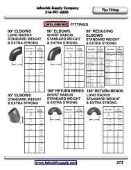
Pipe Fittings<br />
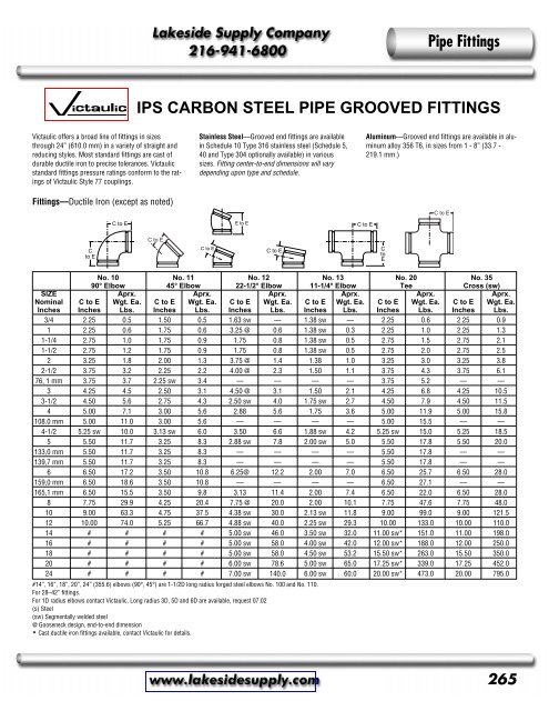
<strong>IPS</strong> <strong>CARBON</strong> <strong>STEEL</strong> <strong>PIPE</strong> <strong>GROOVED</strong> <strong>FITTINGS</strong><br />
Victaulic offers a broad line of fittings in sizes<br />
through 24” (610.0 mm) in a variety of straight and<br />
reducing styles. Most standard fittings are cast of<br />
durable ductile iron to precise tolerances. Victaulic<br />
standard fittings pressure ratings conform to the ratings<br />
of Victaulic Style 77 couplings.<br />
Stainless Steel—Grooved end fittings are available<br />
in Schedule 10 Type 316 stainless steel (Schedule 5,<br />
40 and Type 304 optionally available) in various<br />
sizes. Fitting center-to-end dimensions will vary<br />
depending upon type and schedule.<br />
Aluminum—Grooved end fittings are available in aluminum<br />
alloy 356 T6, in sizes from 1 - 8” (33.7 -<br />
219.1 mm.)<br />
Fittings—Ductile Iron (except as noted)<br />
C to E<br />
C to E<br />
E to E<br />
C to E<br />
C to E<br />
C<br />
to E<br />
C to E<br />
C to E<br />
C<br />
to<br />
E<br />
No. 10 No. 11 No. 12 No. 13 No. 20 No. 35<br />
90° Elbow 45° Elbow 22-1/2° Elbow 11-1/4° Elbow Tee Cross (sw)<br />
SIZE Aprx. Aprx. Aprx. Aprx. Aprx. Aprx.<br />
Nominal C to E Wgt. Ea. C to E Wgt. Ea. C to E Wgt. Ea. C to E Wgt. Ea. C to E Wgt. Ea. C to E Wgt. Ea.<br />
Inches Inches Lbs. Inches Lbs. Inches Lbs. Inches Lbs. Inches Lbs. Inches Lbs.<br />
3/4 2.25 0.5 1.50 0.5 1.63 sw — 1.38 sw — 2.25 0.6 2.25 0.9<br />
1 2.25 0.6 1.75 0.6 3.25 @ 0.6 1.38 sw 0.3 2.25 1.0 2.25 1.3<br />
1-1/4 2.75 1.0 1.75 0.9 1.75 0.8 1.38 sw 0.5 2.75 1.5 2.75 2.1<br />
1-1/2 2.75 1.2 1.75 0.9 1.75 0.8 1.38 sw 0.5 2.75 2.0 2.75 2.5<br />
2 3.25 1.8 2.00 1.3 3.75 @ 1.4 1.38 1.0 3.25 3.0 3.25 3.8<br />
2-1/2 3.75 3.2 2.25 2.2 4.00 @ 2.3 1.50 1.1 3.75 4.3 3.75 6.1<br />
76, 1 mm 3.75 3.7 2.25 sw 3.4 — — — — 3.75 5.2 — —<br />
3 4.25 4.5 2.50 3.1 4.50 @ 3.1 1.50 2.1 4.25 6.8 4.25 10.5<br />
3-1/2 4.50 5.6 2.75 4.3 2.50 sw 4.0 1.75 sw 2.7 4.50 7.9 4.50 11.5<br />
4 5.00 7.1 3.00 5.6 2.88 5.6 1.75 3.6 5.00 11.9 5.00 15.8<br />
108.0 mm 5.00 11.0 3.00 5.6 — — — — 5.00 15.5 — —<br />
4-1/2 5.25 sw 10.0 3.13 sw 6.0 3.50 6.6 1.88 sw 4.2 5.25 sw 15.0 5.25 18.5<br />
5 5.50 11.7 3.25 8.3 2.88 sw 7.8 2.00 sw 5.0 5.50 17.8 5.50 20.0<br />
133,0 mm 5.50 11.7 3.25 8.3 — — — — 5.50 17.8 — —<br />
139,7 mm 5.50 11.7 3.25 8.3 — — — — 5.50 17.8 — —<br />
6 6.50 17.2 3.50 10.8 6.25@ 12.2 2.00 7.0 6.50 25.7 6.50 28.0<br />
159,0 mm 6.50 18.6 3.50 10.8 — — — — 6.50 27.1 — —<br />
165,1 mm 6.50 15.5 3.50 9.8 3.13 11.4 2.00 7.4 6.50 22.0 6.50 28.0<br />
8 7.75 29.9 4.25 20.4 7.75 @ 20.0 2.00 10.1 7.75 47.6 7.75 48.0<br />
10 9.00 63.3 4.75 37.5 4.38 sw 30.0 2.13 sw 11.8 9.00 99.0 9.00 121.5<br />
12 10.00 74.0 5.25 66.7 4.88 sw 40.0 2.25 sw 29.3 10.00 133.0 10.00 110.0<br />
14 # # # # 5.00 sw 46.0 3.50 sw 32.0 11.00 sw* 151.0 11.00 198.0<br />
16 # # # # 5.00 sw 58.0 4.00 sw 42.0 12.00 sw* 188.0 12.00 250.0<br />
18 # # # # 5.00 sw 58.0 4.50 sw 53.2 15.50 sw* 263.0 15.50 350.0<br />
20 # # # # 6.00 sw 78.6 5.00 sw 65.0 17.25 sw* 339.0 17.25 452.0<br />
24 # # # # 7.00 sw 140.0 6.00 sw 60.0 20.00 sw* 473.0 20.00 795.0<br />
#14”, 16”, 18”, 20”, 24” (355.6) elbows (90°, 45°) are 1-1/2D long radius forged steel elbows No. 100 and No. 110.<br />
For 28–42” fittings.<br />
For 1D radius elbows contact Victaulic. Long radius 3D, 5D and 6D are available, request 07.02<br />
(s) Steel<br />
(sw) Segmentally welded steel<br />
@ Gooseneck design, end-to-end dimension<br />
* Cast ductile iron fittings available, contact Victaulic for details.<br />
265
Pipe Fittings<br />
<strong>IPS</strong> <strong>CARBON</strong> <strong>STEEL</strong> <strong>PIPE</strong> <strong>GROOVED</strong> <strong>FITTINGS</strong><br />
No. 33<br />
True Wye<br />
Segmentally Welded Steel<br />
No. 29M<br />
Tee with Thd. Branch<br />
Ductile Iron<br />
No. 100 & No. 110<br />
90° and 45° Long Radius Elbows 1-1/2 D<br />
Ductile Iron<br />
No. 48<br />
Hose Nipple (U.S.)<br />
Steel<br />
C to LE<br />
C to<br />
GE<br />
C to E<br />
E to E<br />
C to E<br />
C to<br />
SE<br />
C to TE<br />
3D Cast Elbows<br />
For Abrasive Services<br />
Long Radius Elbows<br />
Steel<br />
No. 41 – ANSI 125<br />
No. 45 – ANSI 150<br />
No. 46 – ANSI 300<br />
Flanged Adapter Nipples<br />
No. 80<br />
Female Threaded Adapter<br />
Ductile Iron<br />
C to E<br />
C to E<br />
90° Elbow–3D<br />
45° Elbow–3D<br />
No. 10<br />
No. 30<br />
45° Lateral<br />
Segmentally Welded Steel<br />
No. R-10<br />
Reducing Base Support Elbows<br />
Ductile Iron<br />
Fabricated Fittings<br />
Steel<br />
Victaulic offers a broad line of segmentally<br />
welded fittings in sizes through 24"<br />
(610.0 mm) in a variety of straight and<br />
reducing styles. Fittings are fabricated<br />
of ASTM A-53 carbon steel, or other<br />
materials by special order. Victaulic<br />
segmentally welded fittings pressure<br />
ratings conform to the ratings of Victaulic<br />
Style 77 couplings.<br />
All fittings are grooved to permit fast<br />
installation without field preparation.<br />
The grooved design permits flexibility<br />
for easy alignment.<br />
No. 60, 40, 42, 43<br />
Cap and Nipples<br />
Cap – Ductile Iron<br />
Nipples – Steel<br />
266
Pipe Fittings<br />
<strong>IPS</strong> <strong>CARBON</strong> <strong>STEEL</strong> <strong>PIPE</strong> <strong>GROOVED</strong> <strong>FITTINGS</strong><br />
No. 52<br />
Reducer Threaded Small End<br />
No. 53,54,55<br />
Swaged Nipples* – Steel<br />
No. 50 & No. 51<br />
Concentric/Eccentric Reducers<br />
Steel<br />
*Also available in threaded small end<br />
No. 54 or threaded large end No. 55.<br />
No. 25 & No. 29<br />
Reducing Tees<br />
Segmentally Welded Steel<br />
No. 18 & No. 19<br />
Adapter Elbows<br />
Ductile Iron<br />
No. 61<br />
Bull Plug<br />
Steel<br />
No. 21<br />
Bullhead Tee<br />
Ductile Iron<br />
No. 27<br />
Sandpipe Tee<br />
Ductile Iron<br />
No. 32<br />
Tee Wye<br />
Segmentally Welded Steel<br />
No. 30-R<br />
Reducing Lateral<br />
Segmentally Welded Steel<br />
No. 32-R<br />
Reducing Tee Wye<br />
Segmentally Welded Steel<br />
267
Pipe Fittings<br />
<strong>IPS</strong> <strong>CARBON</strong> <strong>STEEL</strong> <strong>PIPE</strong> <strong>GROOVED</strong> COUPLINGS<br />
Style 07<br />
Zero-Flex ® Rigid Coupling<br />
The unique angle-pad design of Zero-Flex® Style 07 adjusts to standard pipe and roll or cut<br />
groove tolerances, positively clamping the pipe to resist flexural and torsional loads. Wider key<br />
section fills more of the groove area.<br />
Style 77<br />
Standard Flexible Coupling<br />
Style 77 couplings are designed with cross-ribbed construction to provide a strong component for<br />
pressure piping systems. Sizes 3/4-12" (26.9 - 323.9 mm) are two-piece housings. Sizes 14 - 22"<br />
(355.6 - 559.0 mm) are cast in four identical segments, with larger sizes cast in six segments.<br />
Style 770<br />
Standard Coupling for Roll<br />
Grooved Pipe<br />
Style 770 couplings are designed for joining large diameter piping systems. Ranging in size from<br />
28" (711.0 mm) to 42" (1067.0 mm), Style 770 is ideal for roll grooved <strong>IPS</strong> black or galvanized<br />
steel and stainless steel systems.<br />
Style 75<br />
Flexible Coupling<br />
Style 75 is available where moderate pressures are expected or weight considerations are a factor.<br />
Up to 50% lighter in weight than the Style 77, the Style 75 coupling is recommended for service<br />
up to 500 PSI (3450 kPa) depending on size.<br />
Style 741<br />
Vic-Flange ® Adapter<br />
ANSI Class 125 & 150 Flange<br />
Sizes 2 - 12” (60.3 - 323.9 mm)<br />
Style 741 Vic-Flange adapter is designed for directly incorporating flanged components with ANSI<br />
CL 125 or CL 150 bolt hole patterns into a grooved pipe system. Sizes 2 - 12” (60.3 - 323.9 mm)<br />
are hinged for easy handling with integral end tabs to facilitate assembly.<br />
Style 743<br />
Vic-Flange ® Adapter<br />
Grooved pipe adapter to<br />
ANSI Class 300 flanges<br />
Vic-Flange Style 743 flange-to-groove adapter permits direct connection of ANSI Class 300 raised<br />
face flanged components. It can be used with flat-face flanges by removing the raised projections<br />
on the outside face of the flange.<br />
Style 741<br />
Vic-Flange ® Adapter<br />
ANSI Class 125 & 150 Flange<br />
Sizes 14 - 24” (355.6 - 610.0 mm)<br />
Style HP-70<br />
Rigid Coupling<br />
Style HP-70ES<br />
Coupling with Fire-R Gasket<br />
Style 741 Vic-Flange adapter is designed for directly incorporating flanged components with ANSI<br />
CL. 125 or CL. 150 bolt hole patterns into a grooved pipe system. Sizes 14 - 24” (355.6 - 610.0<br />
mm) are cast in four (4) identical segments which interconnect as assembly is completed.<br />
Style HP-70 is designed to clamp the pipe, thus providing an essentially rigid joint. To achieve<br />
rigidity it is necessary to torque the bolts on sizes 2 - 4” (60.3 - 114.3 mm) to 60 - 80 ft. lbs. (80 -<br />
110 N•m); 14 - 16” (355.6 - 406.4 mm) to 600 and 700 ft. lbs. (800 and 950 N•m), respectively.<br />
The nuts on the 14 & 16” (355.6 & 406.4 mm) sizes are torqued to 600 & 700 ft. lbs. (810 & 950<br />
N•m), respectively. All other sizes must be bolted securely metal-to-metal.<br />
The Victaulic HP-70ES EndSeal coupling has an oil-resistant nitrile gasket with a high modulus for<br />
resistance to extrusion. The Fire-R gasket features a stainless steel inner leg that provides a secondary<br />
closure. Style HP-70ES with Fire-R gasket is fire tested to API 607 standards.<br />
268
Pipe Fittings<br />
<strong>IPS</strong> <strong>CARBON</strong> <strong>STEEL</strong> <strong>PIPE</strong> <strong>GROOVED</strong> VALVES<br />
Vic ® -300<br />
Butterfly Valves<br />
Series 712 & 713<br />
Swinger ® Check Valve<br />
Series 779<br />
Venturi-Check Valves<br />
Lever Lock<br />
Tamper Resistant<br />
Gear Operator<br />
Vic-300 butterfly valves are designed for services<br />
from vacuum to 300 PSI (2065 kPa). Vic-<br />
300 butterfly valves feature a narrow profile<br />
disc design with a smooth, coated inner body<br />
which combine for superior flow characteristics.<br />
This combination results in extremely low<br />
break-away torque, reducing gear operator and<br />
actuator sizing and costs. Standard polyphenylene<br />
sulfide blend (PPS) coating accommodates<br />
a wide variety of severe services (epoxy coating<br />
or full stainless body are available for severe<br />
services). The dual-seal disc provides bubbletight<br />
sealing up to 300 PSI (2065 kPa) in both<br />
directions without added valve modifications or<br />
cost.<br />
Series 700<br />
Butterfly Valves<br />
Series 712 Series 713<br />
Series 712 Swinger ® swing check valves have<br />
large closure access bonnet for internal coating.<br />
A 316 stainless steel clapper features a bonded<br />
bumper for coating protection.<br />
Series 712 swing check valves are rated to 300<br />
PSI (2065 kPa) service.<br />
A 2" (60.3 mm) size stainless steel model is<br />
also available.<br />
Series 713 is available in 2" (60.3 mm) size<br />
rated to 1000 PSI (6900 kPa).<br />
Series 716<br />
Vic-Check ® Valves<br />
The Victaulic Series 779 Venturi-Check valves<br />
provide a versatility of service unlike any flow<br />
measuring device. The CAD-designed hydrodynamic<br />
inlet profile provides a natural venturi as<br />
part of the valve. The inlet is drilled, tapped and<br />
plugged, ready to receive the flow kit (included).<br />
The venturi-like taps provide much greater measurement<br />
accuracy than taps placed across the<br />
valve seat. Valve turbulence and interference<br />
across the valve seat need not be a consideration.<br />
Twin taps on both sides of the valve provide<br />
positioning of measurement outlets for<br />
convenient meter connection.<br />
Every valve is factory tested and rated to 300<br />
PSI (2065 kPa) working pressure. All sizes can<br />
be installed in horizontal or vertical position and<br />
provide leak-free sealing under conditions as<br />
low as five feet (1.5 m) of head pressure.<br />
Victaulic Series 700 butterfly valves are<br />
designed for bubble-tight shut-off to 200 PSI<br />
(1400 kPa). Two-piece stem permits narrow<br />
disc design for low pressure drop performance<br />
and is self-centering for positive shut-off.<br />
Valves are available with EPDM for water service<br />
to +230°F (+110°C) or nitrile for oil services<br />
to +150°F (+66°C) liners. Refer to<br />
Liner/Disc Selection for general service recommendations.<br />
Typical 2-1/2 & 3" Sizes<br />
Typical 4 - 14" Sizes<br />
The Series 716 check valve is available in sizes<br />
2-1/2–14" (73.0–355.6 mm). It is a spring<br />
assisted single disc design that achieves a leakfree<br />
seal with as little as 5 ft. (1.5 m) of head<br />
and can be installed in both horizontal and vertical<br />
positions.<br />
Every valve is factory tested to its working pressure<br />
of 300 PSI (2065 kPa). Drains are optional<br />
both upstream and downstream of the disc.<br />
Series 377<br />
Vic-Plug Balancing Valve<br />
Series 377 Vic-Plug balancing valve is the first<br />
eccentric grooved end plug valve for throttling<br />
services. Victaulic Style 307 Transition couplings<br />
are available (3–12"/88.9–323.9 mm) to<br />
directly connect Vic-Plug valves to grooved end<br />
steel and other <strong>IPS</strong> pipe.<br />
269
Pipe Fittings<br />
CIRCUIT BALANCING VALVES<br />
The TA Hydronics* balancing valves offer a<br />
reliable, simple and cost effective way to measure<br />
and balance all flow rates. Full throttling<br />
range is achieved by 4, 8, 12 or 16 full turns<br />
of the hand wheel, enabling a more precise<br />
setting.<br />
Actual pressure drops are difficult to establish<br />
by calculation. Water flows are frequently<br />
incorrect. They can be corrected easily by<br />
regulating the desired water flow with TA<br />
Hydronics Globe Style Balancing Valves. By<br />
measuring the pressure drop across measuring<br />
ports at a particular hand wheel setting,<br />
the water flow for the valve size can be read<br />
easily from the appropriate pressure drop<br />
graph.<br />
Series 785, 786 and 787 have full Ametal*<br />
copper alloy bodies which obviate dielectric<br />
connections. Series 788 and 789 have ductile<br />
iron bodies and Ametal trim.<br />
All valves are rated to +250°F (+120°C) and<br />
–22°F (-30°C), but service will be governed by<br />
the connecting coupling gasket ratings.<br />
*Registered trademark of TA Hydronics.<br />
Series 785<br />
TBV-S<br />
Sweated End “Mini” (125 PSI)<br />
Series 786<br />
STAS<br />
Solder End (300 PSI)<br />
Series 787<br />
STAD<br />
NPT (Fem.) End (300 PSI)<br />
A<br />
B<br />
Dim.–In./mm<br />
SIZE<br />
Aprx.<br />
Nom. In. Hgt. Wgt. Ea.<br />
Actual mm A B† Lbs./kg<br />
1/2 2.63 2.88 1.0<br />
21.3 67.0 73.0 0.5<br />
3/4 3.16 2.56 1.0<br />
26.9 80.2 65.0 0.5<br />
†Overall height with valve fully<br />
opened.<br />
Drain Kit<br />
(Optional)<br />
A<br />
B<br />
Dim.–In./mm<br />
SIZE<br />
Aprx.<br />
Nom. In. Hgt. Wgt. Ea.<br />
Actual mm A B† Lbs./kg<br />
1/2 3.50 4.00 1.4<br />
21.3 89.0 102.0 0.6<br />
3/4 3.81 4.00 1.4<br />
26.9 97.0 102.0 0.6<br />
1 4.31 4.50 1.9<br />
33.7 110.0 114.0 0.9<br />
1-1/4 4.88 4.31 2.4<br />
42.4 124.0 110.0 1.1<br />
1-1/2 5.13 4.75 3.1<br />
48.3 130.0 121.0 1.4<br />
2 6.13 4.75 4.5<br />
60.3 156.0 121.0 2.0<br />
†Overall height with valve fully<br />
opened.<br />
Drain Kit<br />
(Optional)<br />
A<br />
B<br />
Dim.–In./mm<br />
SIZE<br />
Aprx.<br />
Nom. In. Hgt. Wgt. Ea.<br />
Actual mm A B† Lbs./kg<br />
1/2 3.50 4.00 1.5<br />
21.3 89.0 102.0 0.7<br />
3/4 3.81 4.00 1.6<br />
26.9 97.0 102.0 0.7<br />
1 4.31 4.50 2.0<br />
33.7 110.0 114.0 0.9<br />
1-1/4 4.88 4.31 2.6<br />
42.4 124.0 110.0 1.2<br />
1-1/2 5.13 4.75 3.3<br />
48.3 130.0 121.0 1.5<br />
2 6.13 4.75 5.0<br />
60.3 156.0 121.0 2.3<br />
†Overall height with valve fully<br />
opened.<br />
Series 787-U<br />
A<br />
B<br />
Dim.–In./mm<br />
SIZE<br />
Aprx.<br />
Nom. In. Hgt. Wgt. Ea.<br />
Actual mm A B† Lbs./kg<br />
1/2 4.81 4.00 1.7<br />
21.3 122 102 0.8<br />
3/4 5.13 4.00 1.8<br />
26.9 130 102 0.8<br />
1 6.00 4.50 2.2<br />
33.7 152 114 1.0<br />
†Overall height with valve fully<br />
opened.<br />
Series 788<br />
STAF<br />
Flanged End (250 PSI)<br />
A<br />
D<br />
B<br />
Dim.–In./mm<br />
SIZE<br />
Aprx.<br />
Nom. In. Hgt. Wgt. Ea.<br />
Actual mm A B† Lbs./kg<br />
2-1/2 11.38 7.88 29.0<br />
73.0 289.0 200.0 13.2<br />
3 12.25 8.50 38.0<br />
88.9 311.0 216.0 17.2<br />
4 13.75 9.00 50.0<br />
114.3 350.0 229.0 22.7<br />
5 15.75 10.50 74.0<br />
141.3 400.0 267.0 33.6<br />
6 18.88 11.25 101.0<br />
168.3 480.0 286.0 45.8<br />
8 23.63 17.75 243.0<br />
219.1 600.0 451.0 110.2<br />
10 28.75 18.50 324.0<br />
273.0 730.0 470.0 147.0<br />
12 33.50 20.50 463.0<br />
323.9 851.0 521.0 208.4<br />
†Overall height with valve fully<br />
opened.<br />
Series 789<br />
STAG<br />
Grooved End (300 PSI)<br />
A<br />
B<br />
Dim.–In./mm<br />
SIZE<br />
Aprx.<br />
Nom. In. Hgt. Wgt. Ea.<br />
Actual mm A B† Lbs./kg<br />
2-1/2 11.38 7.88 14.0<br />
73.0 289.0 200.0 6.4<br />
3 12.25 8.50 20.0<br />
88.9 311.0 216.0 9.1<br />
4 13.75 9.00 31.0<br />
114.3 350.0 229.0 14.1<br />
5 15.75 10.50 50.0<br />
141.3 400.0 267.0 22.7<br />
6 18.88 11.25 69.0<br />
168.3 480.0 286.0 31.3<br />
8 23.63 17.75 175.0<br />
219.1 600.0 451.0 78.8<br />
10 28.75 18.50 240.0<br />
273.0 730.0 470.0 108.0<br />
12 33.50 20.50 360.0<br />
323.9 851.0 521.0 162.0<br />
†Overall height with valve fully<br />
opened.<br />
270
Pipe Fittings<br />
<strong>IPS</strong> <strong>CARBON</strong> <strong>STEEL</strong> <strong>PIPE</strong> <strong>GROOVED</strong> END ACCESSORIES<br />
Style 731<br />
Suction Diffuser<br />
Victaulic Style 731 Suction-Diffuser provides optimum flow conditions at the inlet side of the<br />
pump. Each suction diffuser is provided with a removable strainer and a fine mesh sleeve<br />
which acts as a start-up strainer. A 1-1/4" (42.4 mm) pipe support boss is provided for<br />
support and side taps for pressure measurement. A plug is also provided to allow for easy<br />
draining of the system. Victaulic Style 731 is rated at 300 PSI (2065 kPa) working pressure.<br />
Style 730<br />
Vic-Strainer ® – Tee Type<br />
Style 732<br />
Vic-Strainer – Wye Type<br />
Style 150<br />
Mover ® Expansion Joint<br />
Style 155<br />
Expansion Joint<br />
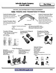
Style 47<br />
Dielectric Waterway Fittings<br />
Clearflow* Dielectric<br />
Waterway fittings create<br />
a dielectric waterway by<br />
insulating the inside of<br />
the metal casing, thus<br />
inhibiting the internal formation<br />
of galvanic local<br />
cell corrosion between<br />
the dissimilar metals in<br />
the presence of water.<br />
Style 47-GG<br />
Grooved End Steel (<strong>IPS</strong>) to Grooved<br />
Copper (CTS) Transition Fitting<br />
Clearflow fittings use<br />
materials which meet the<br />
requirements of ASTM F-<br />
492-77. Clearflow fittings<br />
are designed for continuous<br />
use at temperatures<br />
up to 230°F (110°C) and<br />
pressures up to 300 PSI<br />
(2065 kPa).<br />
1. Inert, non-corrosive thermoplastic lining (NSF/FDA<br />
listed)<br />
2. Patented ring-groove locks the steel casting to the<br />
thermoplastic lining, or molded liner with identifying<br />
roll marking on casing.<br />
3. Zinc electroplated casing, threaded in accordance<br />
with American National Pipe Thread – Tapered<br />
(ANSI A1.20.1)<br />
Style 47-GT and 47-TT<br />
<strong>IPS</strong> Carbon Steel Pipe<br />
Hole Cut Products<br />
Styles 920 & 920N<br />
Mechanical-T ® Bolted Branch Outlet<br />
Styles 920 and 920N<br />
w/Grooved Outlet<br />
Style 47-GT<br />
Grooved X Threaded<br />
Grooved X Threaded<br />
2 - 3" Sizes 4 - 8" Sizes<br />
Style 47-GG<br />
Grooved X Grooved<br />
*Clearflow is a registered trademark of Perfection Corp.<br />
Style 47-TT<br />
Threaded X Threaded<br />
Threaded X Threaded<br />
Styles 920 and 920N<br />
w/Female Threaded Outlet<br />
271
Pipe Fittings<br />
<strong>IPS</strong> <strong>CARBON</strong> <strong>STEEL</strong> <strong>PIPE</strong> HOLE CUT PRODUCTS<br />
Style 923<br />
Vic-Let Strapless Outlet<br />
4 - 8" <strong>IPS</strong> 10" and larger<br />
The Victaulic Style 923 Vic-Let outlet has<br />
integral lugs which insert into a hole cut in<br />
the pipe, gripping against the pipe’s inside<br />
wall, while a nut threaded on the main<br />
body is tightened.<br />
Style 923 Vic-Let outlets are rated at 300<br />
PSI (2065 kPa) working pressure for standard<br />
weight steel pipe.<br />
Style 924<br />
Vic-O-Well Strapless Thermometer Outlet<br />
The Victaulic Style 924 Vic-O-Well outlet<br />
main body casting has integral lugs which<br />
insert into a hole, gripping against the I.D.<br />
wall, while a nut threaded on the main<br />
body. The Vic-O-Well outlet main body is<br />
machined internally to standard thread well<br />
dimensions. Both sizes are rated at 300<br />
PSI (2065 kPa) working pressure on steel<br />
pipe.<br />
4 - 8" Sizes 10" and larger<br />
<strong>IPS</strong> Carbon Steel Pipe Pressfit System<br />
The Pressfit® System offers economy, speed<br />
and reliability for joining small diameter pipe<br />
for fire protection, heating/air conditioning and<br />
many other services.<br />
Pressfit products for carbon steel pipe are<br />
externally zinc electroplated.<br />
Pressfit carbon steel is not intended for use in<br />
open loop water systems.<br />
Style 505<br />
Standard Coupling<br />
(P X P)<br />
Style 510<br />
90° Elbow<br />
(P X P)<br />
The system incorporates Schedule 5 steel pipe<br />
from 3/4–2" (26.9–60.3mm), with a system of<br />
Pressfit couplings, elows, tees, reducers and<br />
adapters. This system allows pipe assembly in<br />
seconds. A portable, hand-held electric or<br />
hydraulic tool assembles the fitting on the pipe<br />
with a permanent mechanical attachment.<br />
The Pressfit System for carbon steel is BOCA<br />
listed – HVAC (Cat. 23) and Fire Protection<br />
Style 511<br />
45° Elbow<br />
(P X P)<br />
(Cat. 15). It is Listed by SBCCI PST and ESI in<br />
Report No. 9535.<br />
Pressfit System products are rugged and reliable.<br />
They are UL/ULC Listed and FM Approved<br />
for 175 PSI (1200 kPa) fire protection service<br />
and rated to 300 PSI (2065 kPa) for heating<br />
water and other general services.<br />
Pressfit System also available in stainless.<br />
O-ring—Precisely molded compresses against pipe O.D.<br />
Housing—Precision formed externally zinc electroplated carbon<br />
steel with integral pipe stop<br />
Pipe Stop—Assures uniform take-out dimension and positions<br />
pipe for proper assembly (not on Slip Coupling)<br />
O-ring Pocket—Sized to contain the o-ring, the pocket is<br />
deformed during assembly<br />
Pressfit Tool Indent—Housing is uniformly compressed with<br />
the Pressfit Tool into a permanent mechanical engagement<br />
onto the pipe.<br />
NOTE: Designers of systems exposed to potentially corrosive situations (high humidity, marine<br />
or process environments, etc.) should always consider use of protective coatings on any carbon<br />
steel piping products.<br />
Style 509<br />
Short Tangent<br />
90° Elbow<br />
(P X P)<br />
Style 509<br />
Short Radius<br />
90° Elbow<br />
Reducing<br />
(P X F)<br />
Style 506<br />
Slip Coupling<br />
(P X P)<br />
272
Pipe Fittings<br />
<strong>IPS</strong> <strong>CARBON</strong> <strong>STEEL</strong> <strong>PIPE</strong> PRESSFIT SYSTEM<br />
Style 520<br />
Tee<br />
(P X P X P)<br />
Style 520<br />
Tee<br />
Reducing Branch<br />
(P X P X F)<br />
Style 520<br />
End-of-Line Tee<br />
With Threaded Reducing Branch<br />
(P X C X F)<br />
With Pressfit Reducing Branch<br />
(P X D X P)<br />
Style 522<br />
Brass Body Ball Valve with<br />
Carbon Steel Pressfit Ends<br />
(P X P)<br />
Style 535<br />
Cross<br />
(P X P)<br />
Style 550<br />
Reducer Insert<br />
(T X P)<br />
Style 580<br />
Adapter Female<br />
Threaded<br />
(P X F)<br />
Style 580<br />
Adapter Male Threaded<br />
(P X M)<br />
Approved Pipe<br />
Products in the Pressfit carbon steel system are<br />
easily installed on approved Schedule 5 carbon<br />
steel pipe using the Pressfit tool.<br />
The Pressfit System requires no special preparation<br />
of the pipe ends before assembly. Pipe should<br />
be square cut (±0.030") and deburred, if<br />
required, to prevent damage to the o-ring during<br />
assembly.<br />
Pressfit System carbon steel products are<br />
designed for use only on approved Schedule 5<br />
carbon steel pipe having a maximum yield<br />
strength of 45,000 PSI (310000 kPa) and maximum<br />
hardness of R b<br />
70.<br />
273
Pipe Fittings<br />
<strong>IPS</strong> <strong>CARBON</strong> <strong>STEEL</strong> <strong>PIPE</strong> PLAIN END SYSTEM<br />
Style 99<br />
Roust-A-Bout ®<br />
Coupling<br />
Plain End Fittings<br />
The Style 99 Roust-A-Bout coupling<br />
consists of a durable ductile iron<br />
housing. Its curved, case-hardened<br />
steel jaws grip into the pipe when<br />
nuts are tightened to full torque<br />
specifications, and it requires no<br />
pipe end preparation.<br />
Long Radius Elbows<br />
Long Tangent Elbows<br />
CTS Copper Tubing Grooved Piping System<br />
TUBING – TYPE K, L, M, DWV<br />
Style 606<br />
Coupling for Copper Tubing<br />
The Victaulic copper connection system is for<br />
joining large diameter copper tubing (CTS) in<br />
2–8" (54.0–206.4 mm) sizes.<br />
Patented angled pad design adjusts to standard<br />
tubing tolerances and provides positive clamping<br />
on the tubing to resist flexural and torsional<br />
loads.<br />
The system uses a proven pressure-responsive<br />
synthetic rubber FlushSeal ® gasket to seal on<br />
the outside diameter of the tubing. This means<br />
No. 650<br />
Reducer<br />
no heat is required and no lead is used. The<br />
housing provides the gripping strength for<br />
pressure ratings up to 300 PSI (2065 kPa),<br />
depending on type and size of copper tubing.<br />
No. 652<br />
Reducer<br />
Groove x Groove<br />
Groove x Copper Sweat<br />
Style 641<br />
Vic-Flange ® Adapter for<br />
Copper Tubing<br />
The Style 641 Vic-<br />
Flange ® Adapter provides<br />
a direct<br />
connection from<br />
flanged components<br />
(Cl. 125 and Cl. 150<br />
bolt hole pattern) to<br />
grooved copper tubing,<br />
with integral tabs<br />
to ease handling.<br />
No. 660<br />
Cap<br />
No. 610, No. 611 & No. 620<br />
Elbows and Tee<br />
Victaulic copper fittings are full-flow, standard<br />
radius fittings, supplied roll grooved.<br />
274