Rolling Out New System Solutions! - AIM - Online
Rolling Out New System Solutions! - AIM - Online
Rolling Out New System Solutions! - AIM - Online

You also want an ePaper? Increase the reach of your titles
YUMPU automatically turns print PDFs into web optimized ePapers that Google loves.
ARINC818 at a Glance:<br />
The ARINC818 Specification defines a digital<br />
video link that is used for uncompressed video<br />
data transmission. This Specification enables<br />
Avionics Display manufacturers to<br />
choose the video format that<br />
best suits their Application.<br />
Video formats can differ in<br />
their Frame Rates, resolution,<br />
pixel density, and interlacing<br />
techniques which drive the<br />
required data rates. Different<br />
classes of video transmission are defined, which<br />
vary from simple asynchronous to pixel synchronous<br />
video transmission which require corresponding<br />
display capabilities.<br />
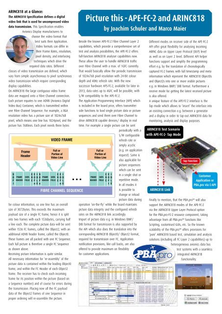
On ARINC818 the large contiguous video frame<br />
data are mapped onto a Fibre Channel connection.<br />
Each picture equates to one ADVB (Avionics Digital<br />
Video Bus) Container, which is transmitted within<br />
one Fibre Channel Sequence. For example, a XGA<br />
resolution video has a picture size of 1024x768<br />
pixel, which means one line has 1024pixel, and the<br />
picture has 768lines. Each pixel needs three bytes<br />
for colour information, so one line has an overall<br />
size of 3072bytes. This exceeds the maximum<br />
payload size of a single FC frame, hence it is split<br />
into two frames with each 1536bytes, carrying half<br />
a line each. The complete picture data will be sent<br />
within 1536 FC frames, called the Object2, with an<br />
additional ADVB header frame, called the Object0.<br />
These frames are all packed with one FC Sequence.<br />
Each full picture is therefore a single FC Sequence<br />
as shown above.<br />
Receiving picture information is quite similar.<br />
All necessary information for ‘re-assembly’ of the<br />
picture data is contained within the leading Object0<br />
frame, and within the FC Header of each Object2<br />
frame. The receiver has to check each incoming<br />
frame for its position within the picture (based on<br />
a Sequence number) and of course for errors during<br />
the transmission. Placing now all the FC payload<br />
data of the Object2 frames of one Sequence in<br />
proper ordering will re-assemble the picture.<br />
Picture this - APE-FC-2 and ARINC818<br />
by Joachim Schuler and Marco Maier<br />
Beside the known APE-FC-2 Fibre Channel Layer 2<br />
capabilities, which provide a comprehensive set of<br />
test and analysis possibilities, the APE-FC-2 offers<br />
full-function ARINC818 analyser capabilities now.<br />
These allow the user to handle ARINC818 traffic<br />
over Fibre Channel with a max. of 1GFC currently.<br />
That would basically allow the periodic transmission<br />
of 1024x768 pixel resolution with 24-Bit colour<br />
depth and 40Hz refresh rate. With the new<br />
successor hardware APS-FC-2, available for later in<br />
2013, data rates up to 4GFC will be possible, with<br />
S/W compatibility to the APE-FC-2.<br />
The Application Programming Interface (API) which<br />
is included in the board price, offers transmitter<br />
side functions to load single picture data or picture<br />
sequences and send them over Fibre Channel to<br />
drive ARINC818 capable devices/ display in real<br />
time. For example a single picture can be sent<br />
periodically with a<br />
S/W configurable<br />
refresh rate or<br />
simply acyclic<br />
(e.g. on application<br />
request). Same is<br />
also applicable for<br />
picture sequences<br />
which can be sent<br />
in a single shot or<br />
repetitive mode.<br />
In all modes it<br />
is possible to<br />
change or reload<br />
picture data during<br />
operation ‘on-the-fly’ while the board maintains<br />
picture data integrity and the configured refresh<br />
rates on the ARINC818 link accordingly.<br />
Import of picture data e.g. in Windows BMP/<br />
DIB format for transmission is also supported by<br />
the API which also does the translation into the<br />
corresponding ARINC818 Object0/ Object2 format,<br />
required for transmission over FC. Application<br />
notification provisions, like call backs, are also<br />
offered to provide maximum on flexibility<br />
for customer applications.<br />
Different modes on receiver side of the APE-FC-2<br />
API offer great flexibility for analysing incoming<br />
ARINC data on Upper Layer Protocol (ULP) level<br />
as well as on Layer 2 level. Different API helper<br />
functions support and simplify the programming<br />
effort e.g. by the translation of chronologically<br />
captured FC-2 frames with full timestamp and meta<br />
information which represent the ARINC818 Object0s<br />
and Object2s into one or more visible pictures<br />
e.g. in Windows BMP/ DIB format. Furthermore a<br />
receive mode for getting the latest received picture<br />
is also offered.<br />
A unique feature of the APE-FC-2 interface is the<br />
Tap mode which allows to ‘insert’ the interface into<br />
an existing connection e.g. between a generator<br />
and a display in order to tap-out ARINC818 data for<br />
monitoring, analysis and display purposes.<br />
ARINC818 Test Scenario<br />
with APE-FC-2- Tap Mode<br />
ARINC818 Link<br />
Tap Function<br />
Customer<br />
Application or<br />
PBA.pro via C-API<br />
Finally to mention, that the PBA.pro TM will also<br />
support the ARINC818 modes of the APE-FC-2<br />
via the ARINC818 Upper Layer Protocol option<br />
for the PBA.pro-FC-2 resource component, taking<br />
advantage from all PBA.pro TM functions like<br />
Scripting, customised GUIs, etc. So the known<br />
scalability of the PBA.pro TM offers provisions for<br />
‘pure’ ARINC818 based test, simulation and analysis<br />
solutions (including all FC Layer 2 capabilities) up to<br />
heterogeneous avionics data bus<br />
test systems with a seamless<br />
integrated ARINC818<br />
functionality.