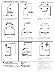
Ground Fault Circuit Protection - carlingtech.com
Ground Fault Circuit Protection - carlingtech.com
Ground Fault Circuit Protection - carlingtech.com

You also want an ePaper? Increase the reach of your titles
YUMPU automatically turns print PDFs into web optimized ePapers that Google loves.
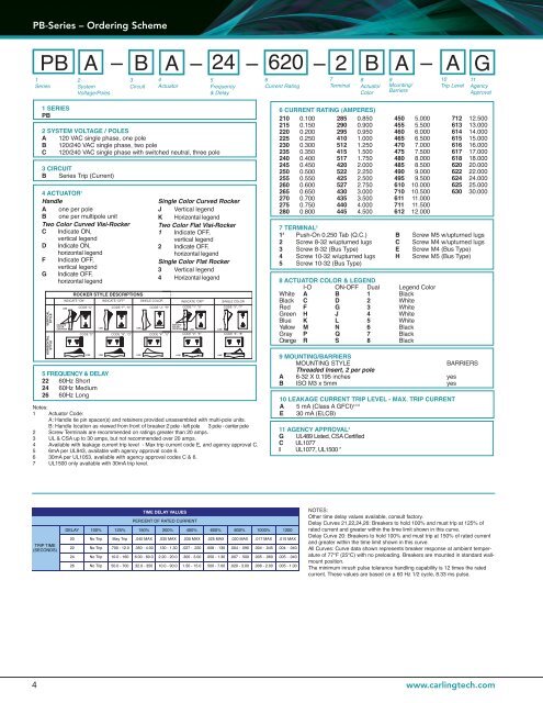
PB-Series – Ordering Scheme<br />
PB<br />
1<br />
Series<br />
A – B A – 24 – 620 – 2 B A – A G<br />
2<br />
System<br />
Voltage/Poles<br />
3<br />
<strong>Circuit</strong><br />
4<br />
Actuator<br />
5<br />
Frequency<br />
& Delay<br />
6<br />
Current Rating<br />
7<br />
Terminal<br />
8<br />
Actuator<br />
Color<br />
9<br />
Mounting/<br />
Barriers<br />
10<br />
Trip Level<br />
11<br />
Agency<br />
Approval<br />
1 SERIES<br />
PB<br />
2 SYSTEM VOLTAGE / POLES<br />
A 120 VAC single phase, one pole<br />
B 120/240 VAC single phase, two pole<br />
C 120/240 VAC single phase with switched neutral, three pole<br />
3 CIRCUIT<br />
B Series Trip (Current)<br />
4 ACTUATOR 1<br />
Handle<br />
A one per pole<br />
B one per multipole unit<br />
Two Color Curved Visi-Rocker<br />
C Indicate ON,<br />
vertical legend<br />
D Indicate ON,<br />
horizontal legend<br />
F Indicate OFF,<br />
vertical legend<br />
G Indicate OFF,<br />
horizontal legend<br />
5 FREQUENCY & DELAY<br />
22 60Hz Short<br />
24 60Hz Medium<br />
26 60Hz Long<br />
Single Color Curved Rocker<br />
J Vertical legend<br />
K Horizontal legend<br />
Two Color Flat Visi-Rocker<br />
1 Indicate OFF,<br />
vertical legend<br />
2 Indicate OFF,<br />
horizontal legend<br />
Single Color Flat Rocker<br />
3 Vertical legend<br />
4 Horizontal legend<br />
Notes:<br />
1 Actuator Code:<br />
A: Handle tie pin spacer(s) and retainers provided unassembled with multi-pole units.<br />
B: Handle location as viewed from front of breaker:2 pole - left pole 3 pole - center pole<br />
2 Screw Terminals are re<strong>com</strong>mended on ratings greater than 20 amps.<br />
3 UL & CSA up to 30 amps, but not re<strong>com</strong>mended over 20 amps.<br />
4 Available with leakage current trip level - Max trip current code E, and agency approval C.<br />
5 6mA per UL943, available with agency approval code 6.<br />
6 30mA per UL1053, available with agency approval codes C & 6.<br />
7 UL1500 only available with 30mA trip level.<br />
6 CURRENT RATING (AMPERES)<br />
210 0.100 285 0.850<br />
215 0.150 290 0.900<br />
220 0.200 295 0.950<br />
225 0.250 410 1.000<br />
230 0.300 512 1.250<br />
235 0.350 415 1.500<br />
240 0.400 517 1.750<br />
245 0.450 420 2.000<br />
250 0.500 522 2.250<br />
255 0.550 425 2.500<br />
260 0.600 527 2.750<br />
265 0.650 430 3.000<br />
270 0.700 435 3.500<br />
275 0.750 440 4.000<br />
280 0.800 445 4.500<br />
7 TERMINAL 2<br />
1 3 Push-On 0.250 Tab (Q.C.)<br />
2 Screw 8-32 w/upturned lugs<br />
3 Screw 8-32 (Bus Type)<br />
4 Screw 10-32 w/upturned lugs<br />
5 Screw 10-32 (Bus Type)<br />
11 AGENCY APPROVAL 3<br />
G UL489 Listed, CSA Certified<br />
C UL1077<br />
I UL1077, UL1500 7<br />
450 5.000<br />
455 5.500<br />
460 6.000<br />
465 6.500<br />
470 7.000<br />
475 7.500<br />
480 8.000<br />
485 8.500<br />
490 9.000<br />
495 9.500<br />
610 10.000<br />
710 10.500<br />
611 11.000<br />
711 11.500<br />
612 12.000<br />
712 12.500<br />
613 13.000<br />
614 14.000<br />
615 15.000<br />
616 16.000<br />
617 17.000<br />
618 18.000<br />
620 20.000<br />
622 22.000<br />
624 24.000<br />
625 25.000<br />
630 30.000<br />
9 MOUNTING/BARRIERS<br />
MOUNTING STYLE<br />
BARRIERS<br />
Threaded Insert, 2 per pole<br />
A 6-32 X 0.195 inches yes<br />
B ISO M3 x 5mm yes<br />
B<br />
C<br />
E<br />
H<br />
8 ACTUATOR COLOR & LEGEND<br />
I-O ON-OFF Dual Legend Color<br />
White A B 1 Black<br />
Black C D 2 White<br />
Red F G 3 White<br />
Green H J 4 White<br />
Blue K L 5 White<br />
Yellow M N 6 Black<br />
Gray P Q 7 Black<br />
Orange R S 8 Black<br />
Screw M5 w/upturned lugs<br />
Screw M4 w/upturned lugs<br />
Screw M4 (Bus Type)<br />
Screw M5 (Bus Type)<br />
10 LEAKAGE CURRENT TRIP LEVEL - MAX. TRIP CURRENT<br />
A 5 mA (Class A GFCI) 4,5,6<br />
E 30 mA (ELCB)<br />
NOTES:<br />
Other time delay values available, consult factory.<br />
Delay Curves 21,22,24,26: Breakers to hold 100% and must trip at 125% of<br />
rated current and greater within the time limit shown in this curve.<br />
Delay Curve 20: Breakers to hold 100% and must trip at 150% of rated current<br />
and greater within the time limit shown in this curve.<br />
All Curves: Curve data shown represents breaker response at ambient temperature<br />
of 77°F (25°C) with no preloading. Breakers are mounted in standard wallmount<br />
position.<br />
The minimum inrush pulse tolerance handling capability is 12 times the rated<br />
current. These values are based on a 60 Hz 1/2 cycle, 8.33 ms pulse.<br />
4<br />
www.<strong>carlingtech</strong>.<strong>com</strong>
![Integrated Solutions Capabilities Brochure [pdf] - carlingtech.com](https://img.yumpu.com/50025031/1/190x190/integrated-solutions-capabilities-brochure-pdf-carlingtechcom.jpg?quality=85)
![H-Series Circuit Breaker - News 2012 [pdf] - Carling Technologies](https://img.yumpu.com/49204089/1/190x245/h-series-circuit-breaker-news-2012-pdf-carling-technologies.jpg?quality=85)
![S-Series Rocker Switch [pdf] - carlingtech.com](https://img.yumpu.com/47646858/1/190x245/s-series-rocker-switch-pdf-carlingtechcom.jpg?quality=85)
![M-Series Circuit Breaker [pdf] - carlingtech.com](https://img.yumpu.com/42286276/1/190x245/m-series-circuit-breaker-pdf-carlingtechcom.jpg?quality=85)

![Miniature Switch Catalog [pdf] - carlingtech.com](https://img.yumpu.com/39979512/1/190x245/miniature-switch-catalog-pdf-carlingtechcom.jpg?quality=85)
![700-800-Series [pdf]](https://img.yumpu.com/39979491/1/190x245/700-800-series-pdf.jpg?quality=85)
![Carling Technologies Supplier Quality Survey [pdf]](https://img.yumpu.com/39979485/1/190x245/carling-technologies-supplier-quality-survey-pdf.jpg?quality=85)