Digital Panel Meter - ERMA-Electronic
Digital Panel Meter - ERMA-Electronic
Digital Panel Meter - ERMA-Electronic

You also want an ePaper? Increase the reach of your titles
YUMPU automatically turns print PDFs into web optimized ePapers that Google loves.
<strong>Panel</strong> mounting instruments /DIN cabinets mountingdifferent standard housing sizesdifferent supply voltagesall usual measured variablesMeasuring instrumentsprogrammableindustrialfair executioncustomized solutions<strong>ERMA</strong>-<strong>Electronic</strong> GmbH - Max-Eyth-Str.8 - 78194 Immendingen - Tel: +49(0)7462/2000-0 - Fax: +49(0)7462/2000-29Technische Änderungen vorbehalten
<strong>Digital</strong> <strong>Panel</strong> <strong>Meter</strong>Quick listCM 2510CF 2610CF 3011CF 5011CF 7000CM 3001CM 3101SSI3005SSI3025MT 251xMT 261xMT 301xMT 501xMT 700xFA 2510(M)(M)Dimensions 48 x 24 mm x x x48 x 24 mm (Mauell-Raster) x x72 x 36 mm96 x 24 mm x x96 x 48 mm x x x x x x144 x 72 mm x x192 x 72 mm x xInput signal Frequency meter x x x x x x xPulse counter x x x x x x xTime meter x x x x x x xIncremental A 90° B x xSerial, RS 232 x x x x xSerial, RS 485 x x x x xSerial, Current Loop (TTY) x x x x xSSI-Interface x xParallelxDisplay range 4-decades x x5-decades x x x x x x x x x6-decades x x x xNumeral height (mm) 8 14 14 25 45 14 14 14 14 8 14 14 25 45 8Power supply AC 95 .. 250 V x x xDC 18 .. 36 V (1) x x x x x x x x x x x x x x xSensor supply DC 24 V/125 mA (1) x x xStandard functions Scaling factor x x x x x x x x x xData buffering x x xOffset value x x x x x x x x x xMIN/MAX-value detection x x xaddressable x x x x xDisplay test x x x x x x x x x x x x x xDisplay hold x x x1 Alarm output (Opto.) x x x x2 Alarm outputs (Relay) x x x x x x xOptions Analog output 10V/20mA x x xRS 232-Interface x x xRS 485-Interface x x xCurrent-Loop-Interface x x x(1) galvanic isolation Technical Subjects To Change<strong>ERMA</strong>-<strong>Electronic</strong> GmbH - Max-Eyth-Straße 8 - D-78194 Immendingen -Tel. +49(0)7462/2000-0 - Fax +49(0)7462/2000-29
<strong>Digital</strong> <strong>Panel</strong> <strong>Meter</strong>A Programmable Totalizing Counter Model CM 2510Highlights• LED Display 8 mm, 5 decades• DIN Housing 48 x 24 mm• Switchboard- or Mosaic System Mounting• Data Memory• Isolated Power Supply• Plug-In Screw TerminalStandard functionsModes• Time meter with start and stop input• Puls counter with direction-input• Cycle duration measurement• Puls duration measurement• Frequency measurement up to 10 kHz• Revolutions per minute• Hour meter• Tachometer m/s or km/hSoftware functions• Scaling factor 0,001 .. 10,000• Offset value for count mode• Count frequency 25 Hz, 7 kHz programmable• Programmable decimal point• Autoranging• Last digit: 1, 2, 5 or 10 steps• Display test<strong>Digital</strong> input channelsThe instrument is provided with four digital input channels.The digital input channels are low active. The digitalinputs are carried out following functions:• Programming• Display testData memoryIn addition to the modes pulse counter and hour metera data memory is effective. When the power is switchedoff the actual display value will be stored and willbe available after the power is switched on again.ProgrammingThe programming is easy and clearly arranged. Bymeans of a programming menue the user is takenthrough this programming. The programming is carriedout through the digital input channels.OptionsHousing type• Switch board mounting DIN 43700• Mosaic system mounting (Subklev, Siemens 8RU)Colour of the front frame• Black• Grey coloured RAL 7037Design of the front• Without front foil• Front foil <strong>ERMA</strong>-<strong>Meter</strong>• Front foil NEUTRAL• Unit overprintDisplay colour• Red• GreenPower supply• 18 .. 36 V DC isolated• optional 12 V DC isolated• optional 5 V DC isolated<strong>ERMA</strong>-<strong>Electronic</strong> GmbH - Max-Eyth-Str.8 - 78194 Immendingen - Tel: +49(0)7462/2000-0 - Fax: +49(0)7462/2000-29Technical Subjects To Change
<strong>Digital</strong> <strong>Panel</strong> <strong>Meter</strong>AProgrammable Totalizing Counter Model CM 2510MHighlights• LED Display 8 mm, 5 decades• Housing for Mauell-Mosaic-SystemsM 24 T, M 24 MK and MK 24x48• Data Memory• Isolated Power Supply• Plug-In Screw TerminalStandard functionsModes• Time meter with start and stop input• Puls counter with direction-input• Cycle duration measurement• Puls duration measurement• Frequency measurement up to 10 kHz• Revolutions per minute• Hour meter• Tachometer m/s or km/hSoftware functions• Scaling factor 0,001 .. 10,000• Offset value for count mode• Count frequency 25 Hz, 7 kHz programmable• Programmable decimal point• Autoranging• Last digit: 1, 2, 5 or 10 steps• Display test<strong>Digital</strong> input channelsThe instrument is provided with four digital input channels.The digital input channels are low active. The digitalinputs are carried out following functions:• Programming• Display testData memoryIn addition to the modes pulse counter and hour metera data memory is effective. When the power is switchedoff the actual display value will be stored and willbe available after the power is switched on again.ProgrammingThe programming is easy and clearly arranged. Bymeans of a programming menue the user is takenthrough this programming. The programming is carriedout through the digital input channels.OptionsHousing type• Mauell-Mosaic-Systems M 24 T, M 24 MK andMK 24x48Colour of the front frame• Black• Grey coloured RAL 7037Design of the front• Without front foil• Front foil <strong>ERMA</strong>-METER• Front foil NEUTRAL• Unit overprintDisplay colour• Red• Green•Power supply• 18 .. 36 V DC isolated• optional 12 V DC isolated• optional 5 V DC isolated<strong>ERMA</strong>-<strong>Electronic</strong> GmbH - Max-Eyth-Str.8 - 78194 Immendingen - Tel: +49(0)7462/2000-0 - Fax: +49(0)7462/2000-29Technical Subjects To Change
<strong>Digital</strong> <strong>Panel</strong> <strong>Meter</strong>Technical dataDisplay: 5 decades, 8 mm, red (opt.green)Display range :-9999 .. 99999Measuring ranges:Time meterPulse counter f maxPeriod durationPulse durationFrequencyRevolutionHour meterTachometer:ResolutionDistance: 10 ms .. 9999,9 s: 25 Hz, 7 kHz programmable: 10 ms .. 9999,9 s: 10 ms .. 9999,9 s: 0,6 Hz .. 9,999 kHz: 42 .. 9999 U/min: 0,02 h .. 9999,9 h: 0,01 m/s or 0,1 km/h: 1 m fix or variable prog.<strong>Digital</strong> input channels:Low level: < 0,4 VHigh level: > 3,5 V, max. 30 VInput resitance:Input 1-4 : 10 k to +5VInput 5: 10 k to GNDPower supply DCoptionaloptional: 18 V to 36 V DC, isolated: 12 V DC, ± 10 %, isolated: 5 V DC, ± 10 %, isolatedOrdering informationCM 2510M -Housing0 Mauell-Mosaic-SystemsFront frame colour0 Black1 Grey coloured RAL 7037Front design0 Without front foil1 Front foil <strong>ERMA</strong>-METER2 Front foil NEUTRALDisplay colour0 Red1 GreenPower supply0 5 V DC, ± 10%, isolated1 12 V DC, ± 10 %, isolated2 18 .. 36 V DC, isolatedUnit overprintPlease specify in clear text at order !Power consumption : approx. 30 mA (red)(18 .. 36 V DC) : approx. 43 mA (green)Housing: Mauell-Mosaic-SystemsM 24 T, M 24 MK, MK 24x48Dimensions: 48 x 24 x 86,5 mmDepth: < 95 mm incl. screw terminalProtection : front IP 40EMV: EMV-conform with 89/336/EWGOperating temperature : 0 .. 50 °CDimensions24,018,448,022,2 +0,3<strong>Panel</strong> CutoutDIN 4370042,945,0 +0,6cm2510m_datas_en.vp/05.12orMauell Mosaic SystemsM24TM24MKMK 24x4811,0<strong>ERMA</strong>-<strong>Electronic</strong> GmbH - Max-Eyth-Str.8 - 78194 Immendingen - Tel: +49(0)7462/2000-0 - Fax: +49(0)7462/2000-2981,55Technical Subjects To Change
<strong>Digital</strong> <strong>Panel</strong> <strong>Meter</strong>A• Programmable Totalizing Counter Model CF 2610Highlights• LED Display 14 mm, 5 decades• DIN Housing 96 x 24 mm• Switchboard- or Mosaic System Mounting• Isolated Power Supply• Plug-In Screw Terminal• Limit Value Output (Optocoupler)Standard functionsModes• Time meter with start and stop-input• Pulse counter with direction-input• Cycle duration measurement• Pulse duration measurement• Frequency measurement up to 10 kHz• Revolution per minute• Hour meter• Tachometer in m/s or km/hSoftware functions• Scaling factor 0,001 .. 9,999• Offset value for count mode• Count frequency 25 Hz, 7 kHz programmable• Programmable decimal point• Autoranging• Last digit in 1, 2, 5 or 10 steps• Display test• Limiting value functions<strong>Digital</strong> input channelsThe instrument is provided with four digital input channels.The input channels are low active. The digital inputchannels are carried out following functions:• Programming• Display testLimiting value output (optocouple)The instrument is provided with a optocouple outputfor limiting value indication. Following functions can beprogrammed:• Alarm point and hysteresis• High or low alarmPower supply• 18 .. 36 V DC isolated• optional 12 V DC isolated• optional 5 V DC isolatedProgrammingThe programming is easy and clearly arranged. Bymeans of a programming menue the user is takenthrough this programming. The programming is carriedout through the digital input channels.OptionsHousing• Switch board mounting DIN 43700• Mosaic system mounting (Subklev, Siemens 8RU)Colour of the front frame• BlackDesign of the front• Without front foil• Front foil <strong>ERMA</strong>-METER• Front foil NEUTRAL• Unit overprintDisplay colour• Red• Green<strong>ERMA</strong>-<strong>Electronic</strong> GmbH - Max-Eyth-Str.8 - 78194 Immendingen - Tel: +49(0)7462/2000-0 - Fax: +49(0)7462/2000-29Technical Subjects To Change
<strong>Digital</strong> <strong>Panel</strong> <strong>Meter</strong>Technical dataDisplay : 5 decades, 14 mm, red (opt.green)Display range :-9999 .. 99999Measuring ranges:Time meter : 10 ms .. 9999,9 sPulse counter f max : 25 Hz, 7 kHz programmableCycle duration : 10 ms .. 9999,9 sPulse duration : 10 ms .. 9999,9 sFrequency : 0,6 Hz .. 9,999 kHzRevolution : 42 .. 9999 U/minHour meter : 0,02 h .. 9999,9 hTochometer:Resolution : 0,01 m/s or 0,1 km/hDistance : 1 m fix or variable<strong>Digital</strong> input channelsLow level: < 0,4 VHigh level: > 3,5 V, max. 30 VInput resistance:Input 3-6 : 10 kΩ to +5VInput 7 : 10 kΩ to GNDLimit value output : optocoupler: max. 10 mA, 70 V, max. 150 mWOrdering informationCF 2610 -Unit overprintHousing0 Switch board mount1 <strong>Panel</strong> clipFront frame colour0 BlackFront design0 Without front foil1 Front foil <strong>ERMA</strong>-METER2 Front foil NEUTRALDisplay colour0 Red1 GreenPower supply0 5 V DC, ± 10%, isolated1 12 V DC, ± 10 %, isolated2 18 .. 36 V DC, isolatedPlease specify in clear text at order !Power supply DC : 18 V to 36 V DC, isolatedoptional : 12 V DC, ± 10 %, isolatedoptional : 5 V DC, ± 10 %, isolatedPower consumption : approx. 65 mA (red)(18 .. 36 V DC) : approx. 75 mA (green)Housing : switch board mounting DIN 43700Dimensions : 96 x 24 x 63,5 mmDepth: < 72 mm incl. screw terminalProtection : front IP 40EMV: in conform with 89/336/EWGOperating temperature : 0 .. 50 °CDimensionsSwitch board mounting <strong>Panel</strong> clipMosaic Systems:Siemens 8RU (M50x25)<strong>Panel</strong> cutoutSubklevDIN 43700+0,888<strong>ERMA</strong>-<strong>Electronic</strong> GmbH - Max-Eyth-Str.8 - 78194 Immendingen - Tel: +49(0)7462/2000-0 - Fax: +49(0)7462/2000-29Technical Subjects To Change
<strong>Digital</strong> <strong>Panel</strong> <strong>Meter</strong>A• Programmable Totalizing Counter Model CF 5010Highlights• LED Display 25 mm, 5 decades• DIN Housing 144 x 72 mm• Switchboard- or Mosaic System Mounting• Isolated Power Supply• Plug-In Screw Terminal• 2 Alarm Relay OutputsStandard functionsModes• Time meter with start and stop-input• Pulse counter with direction-input• Cycle duration measurement• Pulse duration measurement• Frequency measurement up to 10 kHz• Revolution per minute• Hour meter• Tachometer in m/s or km/hSoftware functions• Scaling factor 0,001 .. 10,000• Offset value for count mode• Count frequency 25 Hz, 7 kHz programmable• Programmable decimal point• Autoranging• Last digit in 1, 2, 5 or 10 steps• Display test• Limiting value functions<strong>Digital</strong> input channelsThe instrument is provided with four digital input channels.The input channels are low active. The digital inputchannels are carried out following functions:• Programming• Display testAlarm relay outputsThe instrument is provided with two alarms with relayoutput. For each alarm point there can be programmedfollowing functions:• Alarm point and hysteresis• High or low alarmPower supply• 18 .. 36 V DC isolated• optional 12 V DC isolated• optional 5 V DC isolatedProgrammingThe programming is easy and clearly arranged. Bymeans of a programming menue the user is takenthrough this programming. The programming is carriedout through the digital input channels.OptionsHousing• Switch board mounting DIN 43700• Mosaic system mounting (Siemens 8RU)Colour of the front frame• BlackDesign of the front• Without front foil• Front foil <strong>ERMA</strong>-METER• Front foil NEUTRAL• Unit overprintDisplay colour• Red• Green<strong>ERMA</strong>-<strong>Electronic</strong> GmbH - Max-Eyth-Str.8 - 78194 Immendingen - Tel: +49(0)7462/2000-0 - Fax: +49(0)7462/2000-29Technical Subjects To Change
<strong>Digital</strong> <strong>Panel</strong> <strong>Meter</strong>Technical dataDisplay : 5 decades, 25 mm, red (opt.green)Display range :-9999 .. 99999Measuring ranges:Time meter : 10 ms .. 9999,9 sPulse counter f max : 25 Hz, 7 kHz programmableCycle duration : 10 ms .. 9999,9 sPulse duration : 10 ms .. 9999,9 sFrequency : 0,6 Hz .. 9,999 kHzRevolution : 42 .. 9999 U/minHour meter : 0,02 h .. 9999,9 hTochometer:Resolution : 0,01 m/s or 0,1 km/hDistance : 1 m fix or variable<strong>Digital</strong> input channelsLow level: < 0,4 VHigh level: > 3,5 V, max. 30 VInput resistance:Input 3-6 : 10 kΩ to +5VInput 7 : 10 kΩ to GNDLimit value (relays) : AC max. 5 A, max. 250 V, 1250VA: DC max. 5 A, max. 250 V, 100 WOrdering informationCF 5010 -Unit overprintHousing0 Switch board mount1 <strong>Panel</strong> clipFront frame colour0 BlackFront design0 Without front foil1 Front foil <strong>ERMA</strong>-METER2 Front foil NEUTRALDisplay colour0 Red1 GreenPower supply0 5 V DC, ± 10%, isolated1 12 V DC, ± 10 %, isolated2 18 .. 36 V DC, isolatedPlease specify in clear text at order !Power supply DC : 18 V to 36 V DC, isolatedoptional : 12 V DC, ± 10 %, isolatedoptional : 5 V DC, ± 10 %, isolatedPower consumption : approx. 65 mA (red)(18 .. 36 V DC) : approx. 75 mA (green)Housing : switch board mounting DIN 43700Dimensions : 144 x 72 x 63,5 mmDepth: < 72 mm incl. screw terminalProtection : front IP 40EMV: in conform with 89/336/EWGOperating temperature : 0 .. 50 °CDimensionsSwitch board mounting <strong>Panel</strong> clipMosaic Systems:Siemens 8RU (M50x25)Subklev+1,0158158<strong>ERMA</strong>-<strong>Electronic</strong> GmbH - Max-Eyth-Str.8 - 78194 Immendingen - Tel: +49(0)7462/2000-0 - Fax: +49(0)7462/2000-29Technical Subjects To Change
<strong>Digital</strong> <strong>Panel</strong> <strong>Meter</strong>A• Programmable Totalizing Counter Model CF 7000Highlights• LED Display 45 mm, 4 decades• DIN Housing 192 x 72 mm• Switchboard- or Mosaic System Mounting• Isolated Power Supply• Plug-In Screw Terminal• 2 Alarm Relay OutputsStandard functionsModes• Time meter with start and stop-input• Pulse counter with direction-input• Cycle duration measurement• Pulse duration measurement• Frequency measurement up to 10 kHz• Revolution per minute• Hour meter• Tachometer in m/s or km/hSoftware functions• Scaling factor 0,001 .. 10,000• Offset value for count mode• Count frequency 25 Hz, 7 kHz programmable• Programmable decimal point• Autoranging• Last digit in 1, 2, 5 or 10 steps• Display test• Limiting value functions<strong>Digital</strong> input channelsThe instrument is provided with four digital input channels.The input channels are low active. The digital inputchannels are carried out following functions:• Programming• Display testPower supply• 18 .. 36 V DC isolated• optional 12 V DC isolated• optional 5 V DC isolatedProgrammingThe programming is easy and clearly arranged. Bymeans of a programming menue the user is takenthrough this programming. The programming is carriedout through the digital input channels.OptionsHousing• Switch board mounting DIN 43700• Mosaic system mounting (Subklev)Colour of the front frame• BlackDisplay colour• RedAlarm relay outputsThe instrument is provided with two alarms with relayoutput. For each alarm point there can be programmedfollowing functions:• Alarm point and hysteresis• High or low alarm<strong>ERMA</strong>-<strong>Electronic</strong> GmbH - Max-Eyth-Str.8 - 78194 Immendingen - Tel: +49(0)7462/2000-0 - Fax: +49(0)7462/2000-29Technical Subjects To Change
<strong>Digital</strong> <strong>Panel</strong> <strong>Meter</strong>Technical dataOrdering informationDisplay : 4 decades, 45 mm, redDisplay range :-999 .. 9999Measuring ranges:Time meter : 10 ms .. 999,9 sPulse counter f max : 25 Hz, 7 kHz programmableCycle duration : 10 ms .. 999,9 sPulse duration : 10 ms .. 999,9 sFrequency : 0,6 Hz .. 9,999 kHzRevolution : 42 .. 9999 U/minHour meter : 0,02 h .. 999,9 hTochometer:Resolution : 0,01 m/s or 0,1 km/hDistance : 1 m fix or variable<strong>Digital</strong> input channelsLow level: < 0,4 VHigh level: > 3,5 V, max. 30 VInput resistance:Input 3-6 : 10 kΩ to +5VInput 7 : 10 kΩ to GNDLimit value (relays) : AC max. 5 A, max. 250 V, 1250VA: DC max. 5 A, max. 250 V, 100 WPower supply DC : 18 V to 36 V DC, isolatedoptional : 12 V DC, ± 10 %, isolatedoptional : 5 V DC, ± 10 %, isolatedPower consumption : approx. 70 mA (red)(18 .. 36 V DC)Housing : switch board mounting DIN 43700Dimensions : 192 x 72 x 63,5 mmDepth: < 72 mm incl. screw terminalProtection : front IP 40EMV: in conform with 89/336/EWGOperating temperature : 0 .. 50 °CCF 7000 -Housing0 Switch board mount1 <strong>Panel</strong> clipFront frame colour0 BlackFront design0 Without front foilDisplay colour0 RedPower supply0 5 V DC, ± 10%, isolated1 12 V DC, ± 10 %, isolated2 18 .. 36 V DC, isolatedDimensionsSwitch board mounting <strong>Panel</strong> clipMosaic System:Subklev+1,1158158<strong>ERMA</strong>-<strong>Electronic</strong> GmbH - Max-Eyth-Str.8 - 78194 Immendingen - Tel: +49(0)7462/2000-0 - Fax: +49(0)7462/2000-29Technical Subjects To Change
<strong>Digital</strong> <strong>Panel</strong> <strong>Meter</strong>sA• Programmable Universal Counter Model CM 3001Characteristics• LED-Display, red, 6 decades, 14 mm• Display range -99999 .. 999999• DIN Housing 96 x 48 mm• Operating mode programmable• Data storage at power fail• Accessory power supply for the encoder• 2 alarm relay, analog output, interface• Plug-In screw terminalModes• Incremental A 90° B x 1A 90° B x 2, A 90° B x 4• UP/DOWN + Direction• Puls counter AA-B, A+B, A/B, (A-B)/A, (B-A)/A• Frequency-/Rotation speed measurement AA-B, A+B, A/B, (A-B)/A, (B-A)/A• Cycle duration measurement• Pulse duration measurement• Time meter about Start/StopSoftware functionsThe universal counter is equipped with following func -tions:• Scaling factor 0,00001 .. 9,99999• programmable offset value• MIN/MAX value detection• Auto-Reset for MIN/MAX value• Displaytest and displayhold• Setting of alarm points during measurementSignal inputsThe signal inputs are programmable to several enco -der output logic:• PNP- or NPN-Logic• 5 V (TTL), 12 V or 24 V signal level• 25 Hz signal input filterPush buttons at the frontThe three push buttons could be programmed to follo -wing functions:• No function• Reseting Measured value or MIN/MAX value• Displaying Measured-, MIN- or MAX-Value• Manual alarm point reset• Displaying and setting of alarm points<strong>Digital</strong> Input ChannelThese both input are low active and could be program -med to following functions:• No function• Reseting Measured- or MIN/MAX-value• Displaying Measured-, MIN- or MAX-value• Manual alarm point reset• Displayhold or displaytestAccessory power supply (only at AC-Version)Builtin power supply for encoders, 24 V DC/125 mA,isolated to the further electronic.Alarm outputsTwo (Four at option) programmable alarm outputs withfree allocation allows the monitoring of productionoperation. Programmable parameters:• Alarm point and hysteresis• Relay function (high or low alarm)• Alarm response time (Fall off and put on time)• Data source (Measured-, Hold-, MIN- or MAX-va -lue)Option analog outputThe option analog output is provided with a currentoutput and a voltage output. Both output are isolatedfrom the further electronic.• To scale (offset and final value)• Output 0(2) - 10 V or 0(4) - 20 mA• Data source (Measured-, Hold-, MIN- or MAX-va -lue)Optionen serial interfacesAddition to data communication or to a printer• RS 485• RS 232 (analog output not possible)• Current-Loop, TTY (analog output not possible)<strong>ERMA</strong>-<strong>Electronic</strong> GmbH - Max-Eyth-Str.8 - 78194 Immendingen - Tel: +49(0)7462/2000-0 - Fax: +49(0)7462/2000-29Technical Subjects To Change
<strong>Digital</strong> <strong>Panel</strong> <strong>Meter</strong>sA• Programmable Universal Counter Model CM 3101 up to 1 MHzCharacteristics• LED-Display, red, 6 decades, 14 mm• Display range -99999 .. 999999• DIN Housing 96 x 48 mm• Operating mode programmable• Data storage at power fail• Accessory power supply for the encoder• 2 alarm relay, analog output, interface• Plug-In screw terminalModes• Incremental A 90° B x 1A 90° B x 2, A 90° B x 4• UP/DOWN + Direction• Puls counter AA-B, A+B, A/B, (A-B)/A, (B-A)/A• Frequency-/Rotation speed measurement AA-B, A+B, A/B, (A-B)/A, (B-A)/A• Cycle duration measurement• Pulse duration measurement• Time meter about Start/StopSoftware functionsThe universal counter is equipped with following func -tions:• Scaling factor 0,00001 .. 9,99999• programmable offset value• MIN/MAX value detection• Auto-Reset for MIN/MAX value• Displaytest and displayhold• Setting of alarm points during measurementSignal inputsThe signal inputs are programmable to several enco -der output logic:• PNP- or NPN-Logic• 5 V (TTL), 12 V or 24 V signal level• 25 Hz signal input filterPush buttons at the frontThe three push buttons could be programmed to follo -wing functions:• No function• Reseting Measured value or MIN/MAX value• Displaying Measured-, MIN- or MAX-Value• Manual alarm point reset• Displaying and setting of alarm points<strong>Digital</strong> Input ChannelThese both input are low active and could be program -med to following functions:• No function• Reseting Measured- or MIN/MAX-value• Displaying Measured-, MIN- or MAX-value• Manual alarm point reset• Displayhold or displaytestAccessory power supply (only at AC-Version)Build in power supply for encoders, 24 V DC/125 mA,isolated to the further electronic.Alarm outputsTwo (Four at option) programmable alarm outputs withfree allocation allows the monitoring of production ope -ration.Programmable parameters:• Alarm point and hysteresis• Relay function (high or low alarm)• Alarm response time (Fall off and put on time)• Data source (Measured-, Hold-, MIN- or MAX-va -lue)Option analog outputThe option analog output is provided with a currentoutput and a voltage output. Both output are isolatedfrom the further electronic.• To scale (offset and final value)• Output 0(2) - 10 V or 0(4) - 20 mA• Data source (Measured-, Hold-, MIN- or MAX-va -lue)Optionen serial interfacesAddition to data communication or to a printer• RS 485• RS 232 (analog output not possible)• Current-Loop, TTY (analog output not possible)<strong>ERMA</strong>-<strong>Electronic</strong> GmbH - Max-Eyth-Str.8 - 78194 Immendingen - Tel: +49(0)7462/2000-0 - Fax: +49(0)7462/2000-29Technical Subjects To Change
LED1LED2LED3LED1LED2LED3<strong>Digital</strong> <strong>Panel</strong> <strong>Meter</strong>Elektrical DatasCounter incremantal counter steps 24 BitCount frequency max. 1 MHzUP/DOWN-counter + direction counter steps24 Bitcount frequency max. 1 MHzPuls counter counter steps 24 BitCount frequency max. 1 MHzFrequency/rotation speed1-channel mode max. 1 MHzResolution 0,01 Hz auto., 0,1 Hz, 1 Hz2-channel mode max. 1 MHzResolution 1 HzCycle duration 0,0001 s .. 66 sPulse duration 0,0001 s .. 66 sTime meter 0,0001 s .. 999999 sorAccuracyFrequency measurings < 0,01 %Time measurings < 0,02 %Update rateCounter modes 60 ms00.00.00 h .. 99.59.59 hFrequency-/Time meter 100 msSignal input filter 25 Hz programmableData storage > 10 years (NOVRAM)Signal inputs 4, input A, B, Reset, TorLogic PNP-, NPNSignal level 5 V (TTL), 12 V, 24 V<strong>Digital</strong> user inputs 2, programmable functionLogic NPN, max. 30 VAlarm outputs 2 (4) Relays (programmable asopened contace or closed contact)Signaling 2 LEDs at the frontSwitch voltage 250 V AC / 250 V DCSwitch current 5 A AC / 5 A DCSwitch power 750 VA / 100 WAnalog ouput resolution 16 bitAccuracy ± 0,2% of final valuetNonlinearity ± 0,012 %Voltage 0(2) - 10 V, max. 10 mACurrent 0(4) - 20 mA; max. 500 ΩIsolation voltage 3 kV / 1 minInterfaces RS 485, RS 232, TTYProtocol DIN 66 019 / ISO 1745Isolation voltage 1,6 kV / 1 minPower supply voltage AC 95 V to 250 V/ACIsolation voltage 2,5 kV / 1 minPower supply voltage DC 18 .. 36 V DCIsolation voltage 500 V / 1 minPower consumption AC 9 VA, DC 70 mAAccessory power supply 24 V DC / 125 mA (only at AC)Isolation voltage 500 V / 1 minMechanical DatasDisplay 6 decades, 14 mm, redDecimal point programmablepreliminary zero suppression- sign at negative valuesOperation, keyboard design front membrane with push buttonsCase swicth board mounting DIN 43700Dimensions (B x H x T) 96 x 48 x 141 mmDepth148 mm incl. screw terminalMounting switch board mounting ormosaic-systemsWeightca. 400 gConnection Plug-In screw terminalEnvironmental conditionsOperating temperature 0 .. 50 °CStorage temperature -20 .. 70 °CHumidity < 80 %, not-condensingProtection protective class IIFront protection IP 54Field of application class 2, overvoltage protection IICEOrdering informationCM 3101-in conform with 89/336/EWGNSR 73/23/EWGHousing type0 Switch board1 <strong>Panel</strong>-ClipFront frame colour0 blackFront design0 <strong>ERMA</strong>-<strong>Meter</strong> Logo1 No Logo2 Customer defined LogoPower supply0 95 .. 250 V/AC1 18 .. 36 V/DC, isolatedOption interface0 No interface1 Interface RS 4850 2 Interface RS 2320 3 Interface Current-Loop, TTYOptions0 No options1 With analog output4 in addition two alarm outputsDimensions and MountingSwitch board mounting <strong>Panel</strong>-Clipmmmm<strong>ERMA</strong>-METER<strong>ERMA</strong>-METER96,096,0Mosaic Systems:Siemens 8RU (M50x25)Subklev14,7141,08,014,7141,08,0<strong>ERMA</strong>-<strong>Electronic</strong> GmbH - Max-Eyth-Str.8 - 78194 Immendingen - Tel: +49(0)7462/2000-0 - Fax: +49(0)7462/2000-29Technical Subjects To Change
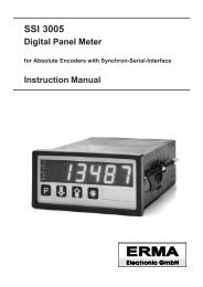
LED1LED2LED3LED1LED2LED3Electrical DataSSI signal input singleturn or multiturnResolution 9 .. 31 bitCodebinary or grayData input receiver RS 422/485Clock input receiver RS 422/485Clock output driver RS 422/485Master modeClock frequency internal 1 MHz, 500 kHz,200 kHz or 100 kHzConversion rate approx. 28 values per secSlave modeClock frequency extern, max. 500 kHzConversation rate approx. 28 values per sec<strong>Digital</strong> inputs 2, programmable functionLogic NPN, max. 30 VAlarm outputs 2 (4) Relays(programmable as normallyopened or normally closedSignaling 2 LEDs at the frontSwitch voltage 250 V AC / 250 V DCSwitch current 5 A AC / 5 A DCSwitch power 750 VA / 100 WAnalog ouput resolution 16 bitAccuracy ± 0,2% of final valuetVoltage 0(2) - 10 V, max. 10 mACurrent 0(4) - 20 mA; max. 500 ΩIsolation voltage 3 kV / 1 minInterfaces RS 485, RS 232, TTYProtocol DIN 66 019 / ISO 1745Isolation voltage 1,6 kV / 1 minPower supply voltage AC 95 V to 250 V/ACIsolation voltage 2,5 kV / 1 minPower supply voltage DC 18 .. 36 V DCIsolation voltage 500 V / 1 minPower consumption AC 9 VA, DC 70 mAAccessory power supply 24 V DC / 125 mA (only atAC)Isolation voltage 500 V / 1 minMechanical DatasDisplay 6 decades, 14 mm, redDecimal point programmablepreliminary zero suppression- sign at negative valuesOperation, keyboard design front membrane with pushbuttonsCaseswicth board mounting DIN43700Dimensions (B x H x T) 96 x 48 x 141 mmDepth148 mm incl. screw terminalMounting switch board mounting ormosaic-systemsWeightca. 400 gConnection Plug-In screw terminal<strong>Digital</strong> DisplayEnvironmental conditionsOperating temperature 0 .. 50 °CStorage temperature -20 .. 70 °CHumidity < 80 %, not-condensingProtection protective class IIFront protection IP 54Field of application class 2, overvoltage protecti -on IICE in conform with 89/336/EWGNSR 73/23/EWGOrdering informationSSI 3005 -Housing0 Switch board1 <strong>Panel</strong> clipFront frame color0 BlackFront design0 <strong>ERMA</strong>-<strong>Meter</strong> logo1 No logo2 Customer defined logoPower supply0 95 .. 250 V/AC1 18 .. 36 V/DC, isolatedOption interface0 No interface1 Interface RS 4850 2 Interface RS 2320 3 Interface TTY (Current-Loop)Options0 No option1 With analog output4 Additional 2 alarm outputsASwitchboard Mounting<strong>Panel</strong> Clip<strong>ERMA</strong>-METERmm<strong>ERMA</strong>-METERmm96,096,0Mosaic Systems:Siemens 8RU (M50x25)Subklev14,7141,08,014,7141,08,0<strong>ERMA</strong>-<strong>Electronic</strong> GmbH - Max-Eyth-Str.8 - 78194 Immendingen - Tel: +49(0)7462/2000-0 Fax:+49(0)7462/2000-29Technische Änderungen vorbehalten
<strong>Digital</strong> <strong>Panel</strong> <strong>Meter</strong>B• Displays with Serial Interface MT 2511, MT 2512 and MT 2513Highlights• Serial Input RS 232, RS 485 or TTY• Addressing• LED Display 8 mm, 5 decades• DIN Housing 48 x 24 mm• Switchboard- or Mosaic System Mounting• Isolated Power Supply• Plug-In Screw TerminalCommentsThe instruments are available with several interfaces:MT 2511• RS 232 signal inputMT 2512• RS 485 signal inputMT 2511• TTY (Current-Loop, 20 mA) signal inputStandard functionsAddressingSeveral instruments can work on one interface. To thiseach instrument gets a own adress.If the displayed signs of the data string is not start atthe first position, it is possible to programm how muchpreceded signs are to ignore.Signs• -, 0, 1, 2, 3, 4, 5, 6, 7, 8, 9, A, B, C, D, E, F• Blank, decimal point• “+” is shown as a blankSoftware functions• Programmable baud rate• 3 selectable address signs• To fade out max. 127 signs• Display test<strong>Digital</strong> input channelsThe instruments are provided with three digital inputchannels. The digital input channels are low active.The digital inputs are carried out following functions:• Programming• Display testPower supply• 18 .. 36 V DC isolated• optional 12 V DC isolated• optional 5 V DC isolatedProgrammingThe programming is easy and clearly arranged. Bymeans of a programming menue the user is takenthrough this programming. The programming is carriedout through the digital input channels.OptionsHousing type• Switch board mounting DIN 43700• Mosaic system mounting (Subklev, Siemens 8RU)Colour of the front frame• Black• Grey coloured RAL 7037• Grey coloured RAL 7032• Grey coloured RAL 7035Design of the front• Without front foil• Front foil ALU• Front foil RAL 7032• Front foil RAL 7035• Unit overprintDisplay colour• Red• Green<strong>ERMA</strong>-<strong>Electronic</strong> GmbH - Max-Eyth-Str.8 - 78194 Immendingen - Tel: +49(0)7462/2000-0 - Fax: +49(0)7462/2000-29Technical Subjects To Change
<strong>Digital</strong> <strong>Panel</strong> <strong>Meter</strong>Technical data Ordering informationDisplay : 5 decades, 8 mm, red (opt.green)Signal inputMT 2511 : RS 232MT 2512 : RS 485MT 2513: TTY (Current-Loop, 20 mA)Data formbitsBaud rate: 1 start bit, 8 data bits, 2 stop: 1200, 2400, 4800, 9600 prog.<strong>Digital</strong> input channels : 10 kΩ to +5VLow level: < 0,4 VHigh level: > 3,5 V, max. 30 VPower supply DC : 18 V to 36 V DC, isolatedoptional : 12 V DC, ± 10 %, isolatedoptional : 5 V DC, ± 10 %, isolatedPower consumption : approx. 30 mA (red)(18 .. 36 V DC) : approx. 40 mA (green)Housing : switch board mounting DIN43700Dimensions : 48 x 24 x 60 mmDepth: < 70 mm incl. screw terminalProtection : front IP 40EMV: EMV-conform with 89/336/EWGOperating temperature : 0 .. 50 °CMT 251x -Unit overprintHousing0 Switch board mount1 <strong>Panel</strong> clipFront frame colour0 Black1 Grey coloured RAL 70372 Grey coloured RAL 70323 Grey coloured RAL 7035Front design0 Without front foil1 Front foil ALU eloxiert2 Front foil RAL 70323 Front foil RAL 7035Display colour0 Red1 GreenPower supply0 5 V DC, ± 10%, isolated1 12 V DC, ± 10 %, isolated2 18 .. 36 V DC, isolatedPlease specify in clear text at order !DimensionsSwitch board mounting <strong>Panel</strong> clipMosaic Systems:Siemens 8RU (M50x25)Subklev<strong>ERMA</strong>-<strong>Electronic</strong> GmbH - Max-Eyth-Str.8 - 78194 Immendingen - Tel: +49(0)7462/2000-0 - Fax: +49(0)7462/2000-29Technical Subjects To Change
<strong>Digital</strong> <strong>Panel</strong> <strong>Meter</strong>B• Displays with Serial Interface MT 2511M, MT 2512M and MT 2513MHighlights• Serial Input RS 232, RS 485 or TTY• Addressing• LED Display 8 mm, 5 decades• Housing for Mauell-Mosaic-SystemsM 24 T, M 24 MK and MK 24x48• Isolated Power Supply• Plug-In Screw TerminalStandard functionsThe instruments are available with several interfaces:MT 2511M• RS 232 signal inputMT 2512M• RS 485 signal inputMT 2513M• TTY (Current-Loop, 20 mA) signal inputAddressingSeveral instruments can work on one interface. To thiseach instrument gets a own address.If the displayed signs of the data string is not start atthe first position, it is possible to programm how muchpreceded signs are to ignore.Signs• -, 0, 1, 2, 3, 4, 5, 6, 7, 8, 9, A, B, C, D, E, F• Blank, decimal point• “+” is shown as a blankSoftware functions• Programmable baud rate• 3 selectable address signs• To fade out max. 127 signs• Display test<strong>Digital</strong> input channelsThe instrument is provided with three digital inputchannels. The digital input channels are low active.The digital inputs are carried out following functions:.Standard functions• Programming• Display testPower supply• 18 .. 36 V DC isolated• optional 12 V DC isolated• optional 5 V DC isolatedProgrammingThe programming is easy and clearly arranged. Bymeans of a programming menue the user is takenthrough this programming. The programming is carriedout through the digital input channels.OptionsHousing type• Mauell-Mosaic-Systems M 24 T, M 24 MK andMK 24x48Colour of the front frame• Black• Grey coloured RAL 7037• Grey coloured RAL 7032• Grey coloured RAL 7035Design of the front• Without front foil• Front foil <strong>ERMA</strong>-METER• Front foil NEUTRAL• Unit overprintDisplay colour• Red• Green<strong>ERMA</strong>-<strong>Electronic</strong> GmbH - Max-Eyth-Str.8 - 78194 Immendingen - Tel: +49(0)7462/2000-0 - Fax: +49(0)7462/2000-29Technical Subjects To Change
<strong>Digital</strong> <strong>Panel</strong> <strong>Meter</strong>Technical dataDisplay : 5 decades, 8 mm,red (opt. green)Signal inputMT 2511M : RS 232MT 2512M : RS 485MT 2513M: TTY (Current-Loop, 20 mA)Data formBaud rate: 1 start bit, 8 data bits, 2 stop bits: 1200, 2400, 4800, 9600 prog.<strong>Digital</strong> input channels : 10 kΩ to +5VLow level: < 0,4 VHigh level: > 3,5 V, max. 30 VPower supply DC : 18 V to 36 V DC, isolatedoptional : 12 V DC, ± 10 %, isolatedoptional : 5 V DC, ± 10 %, isolatedPower consumption : approx. 30 mA (red)(18 .. 36 V DC) : approx. 43 mA (green)Housing : Mauell-Mosaic-SystemsM 24 T, M 24 MK, MK 24x48Dimensions : 48 x 24 x 86,5 mmDepth: < 95 mm incl. screw terminalProtection : front IP 40Ordering informationMT 251xM -Unit overprintHousing0 Mauell-Mosaic-SystemsFront frame colour0 Black1 Grey coloured RAL 70372 Grey coloured RAL 70323 Grey coloured RAL 7035Front design0 Without front foil1 Front foil <strong>ERMA</strong>-METER2 Front foil NEUTRALDisplay colour0 Red1 GreenPower supply0 5 V DC, ± 10%, isolated1 12 V DC, ± 10 %, isolated2 18 .. 36 V DC, isolatedPlease specify in clear text at order !EMV: EMV-conform with 89/336/EWGOperating temperature : 0 .. 50 °CDimensions48,0orMauell Mosaic SystemsM 24 TM 24 MKMK 24x4811,081,5<strong>ERMA</strong>-<strong>Electronic</strong> GmbH - Max-Eyth-Str.8 - 78194 Immendingen - Tel: +49(0)7462/2000-0 - Fax: +49(0)7462/2000-29Technical Subjects To Change
<strong>Digital</strong> <strong>Panel</strong> <strong>Meter</strong>Technical dataDisplay : 5 decades, 14 mm, red(opt. green)Signal inputMT 2611 : RS 232MT 2612 : RS 485MT 2613: TTY (Current-Loop, 20 mA)Data formBaud rate: 1 start bit, 8 data bits, 2 stop bits: 1200, 2400, 4800, 9600 prog.<strong>Digital</strong> input channels : 10 kΩ to +5VLow level: < 0,4 VHigh level: > 3,5 V, max. 30 VLimit value output : optocoupler: max. 10 mA, 70 V, max. 150 mWPower supply DC : 18 V to 36 V DC, isolatedoptional : 12 V DC, ± 10 %, isolatedoptional : 5 V DC, ± 10 %, isolatedPower consumption : approx. 65 mA (red)(18 .. 36 V DC) : approx. 75 mA (green)Housing : switch board mounting DIN 43700Dimensions : 96 x 24 x 63,5 mmDepth: < 72 mm incl. screw terminalProtection : front IP 40Ordering informationMT 261x -Unit overprintHousing0 Switch board mount1 <strong>Panel</strong> clipFront frame colour0 BlackFront design0 Without front foil1 Front foil <strong>ERMA</strong>-METER2 Front foil NEUTRALDisplay colour0 Red1 GreenPower supply0 5 V DC, ± 10%, isolated1 12 V DC, ± 10 %, isolated2 18 .. 36 V DC, isolatedPlease specify in clear text at order !EMV: in conform with 89/336/EWGOperating temperature : 0 .. 50 °CDimensionsSwitch board mounting <strong>Panel</strong> clipMosaic Systems:Siemens 8RU (M50x25)<strong>Panel</strong> cutoutSubklevDIN 43700+0,888<strong>ERMA</strong>-<strong>Electronic</strong> GmbH - Max-Eyth-Str.8 - 78194 Immendingen - Tel: +49(0)7462/2000-0 - Fax: +49(0)7462/2000-29Technical Subjects To Change
<strong>Digital</strong> <strong>Panel</strong> <strong>Meter</strong>B• Displays with Serial Interface MT 3011, MT 3012 and MT 3013Highlights• Serial Input RS 232, RS 485 or TTY• Addressing• LED Display 14 mm, 5 decades• DIN Housing 96 x 48 mm• Switchboard- or Mosaic System Mounting• Isolated Power Supply• Plug-In Screw Terminal• Limit Value Output (Optocoupler)CommentsThe instruments are available with several interfaces:MT 3011• RS 232 signal inputMT 3012• RS 485 signal inputMT 3013• TTY (Current-Loop, 20 mA) signal inputStandard functionsAddressingSeveral instruments can work on one interface. To thiseach instrument gets a own address.If the displayed signs of the data string is not start atthe first position, it is possible to programm how muchpreceded signs are to ignore.Signs• -, 0, 1, 2, 3, 4, 5, 6, 7, 8, 9, A, B, C, D, E, F• Blank, decimal point• “+” is shown as a blankSoftware functions• Programmable baud rate• 3 selectable address signs• To fade out max. 127 signs• Display test• Limiting value functions<strong>Digital</strong> input channelsThe instruments are provided with three digital inputchannels. The input channels are low active. The digitalinput channels are carried out following functions:• Programming• Display testLimiting value output (optocouple)The instruments are provided with a optocouple outputfor limiting value indication. Following functions can beprogrammed:• Alarm point and hysteresis• High or low alarmPower supply• 18 .. 36 V DC isolated• optional 12 V DC isolated• optional 5 V DC isolatedProgrammingThe programming is easy and clearly arranged. Bymeans of a programming menue the user is takenthrough this programming. The programming is carriedout through the digital input channels.OptionsHousing• Switch board mounting DIN 43700• Mosaic system mounting (Subklev, Siemens 8RU)Colour of the front frame• BlackDesign of the front• Without front foil• Front foil <strong>ERMA</strong>-METER• Front foil NEUTRAL• Unit overprintDisplay colour• Red• Green<strong>ERMA</strong>-<strong>Electronic</strong> GmbH - Max-Eyth-Str.8 - 78194 Immendingen - Tel: +49(0)7462/2000-0 - Fax: +49(0)7462/2000-29Technical Subjects To Change
<strong>Digital</strong> <strong>Panel</strong> <strong>Meter</strong>B• Display with Serial Interface MT 5011, MT 5012 and MT 5013Highlights• Serial Input RS 232, RS 485 or TTY• Addressing• LED Display 25 mm, 5 decades• DIN Housing 144 x 72 mm• Switchboard- or Mosaic System Mounting• Isolated Power Supply• Plug-In Screw Terminal• 2 Alarm Relay OutputCommentsThe instruments are available with several interfaces:MT 5011• RS 232 signal inputMT 5012• RS 485 signal inputMT 5013• TTY (Current-Loop, 20 mA) signal inputStandard functionsAddressingSeveral instruments can work on one interface. To thiseach instrument gets a own address.If the displayed signs of the data string is not start atthe first position, it is possible to programm how muchpreceded signs are to ignore.Signs• -, 0, 1, 2, 3, 4, 5, 6, 7, 8, 9, A, B, C, D, E, F• Blank, decimal point• “+” is shown as a blankSoftware functions• Programmable baud rate• 3 selectable address signs• To fade out max. 127 signs• Display test• Limiting value functions<strong>Digital</strong> input channelsThe instrument is provided with three digital inputchannels. The input channels are low active. The digitalinput channels are carried out following functions:• Programming• Display testAlarm relay outputsThe instrument is provided with two alarms with relayoutput. For each alarm point there can be program -med following functions:• Alarm point and hysteresis• High or low alarmPower supply• 18 .. 36 V DC isolated• optional 12 V DC isolated• optional 5 V DC isolatedProgrammingThe programming is easy and clearly arranged. Bymeans of a programming menue the user is takenthrough this programming. The programming is carriedout through the digital input channels.OptionsHousing• Switch board mounting DIN 43700• Mosaic system mounting (Siemens 8RU)Colour of the front frame• BlackDesign of the front• Without front foil• Front foil <strong>ERMA</strong>-METER• Front foil NEUTRAL• Unit overprintDisplay colour• Red• Green<strong>ERMA</strong>-<strong>Electronic</strong> GmbH - Max-Eyth-Str.8 - 78194 Immendingen - Tel: +49(0)7462/2000-0 - Fax: +49(0)7462/2000-29Technical Subjects To Change
<strong>Digital</strong> <strong>Panel</strong> <strong>Meter</strong>B• Display with Serial Interface MT 7001, MT 7002 and MT 7003Highlights• Serial input RS 232, RS 485 or TTY• Addressing• LED Display 45 mm, 4 decades• DIN Housing 192 x 72 mm• Switchboard- or Mosaic System Mounting• Isolated Power Supply• Plug-In Screw Terminal• 2 Alarm Relay OutputCommentsThe instruments are available with several interfaces:MT 7001• RS 232 signal inputMT 7002• RS 485 signal inputMT 7003• TTY (Current-Loop, 20 mA) signal inputStandard functionsAddressingSeveral instruments can work on one interface. To thiseach instrument gets a own address.If the displayed signs of the data string is not start atthe first position, it is possible to programm how muchpreceded signs are to ignore.Signs• -, 0, 1, 2, 3, 4, 5, 6, 7, 8, 9, A, B, C, D, E, F• Blank, decimal point• “+” is shown as a blankSoftware functions• Programmable baud rate• 3 selectable address signs• To fade out max. 127 signs• Display test• Limiting value functions<strong>Digital</strong> input channelsThe instrument is provided with three digital inputchannels. The input channels are low active. The digitalinput channels are carried out following functions:• Programming• Display testAlarm relay outputsThe instrument is provided with two alarms with relayoutput. For each alarm point there can be program -med following functions:• Alarm point and hysteresis• High or low alarmPower supply• 18 .. 36 V DC isolated• optional 12 V DC isolated• optional 5 V DC isolatedProgrammingThe programming is easy and clearly arranged. Bymeans of a programming menue the user is takenthrough this programming. The programming is carriedout through the digital input channels.OptionsHousing• Switch board mounting DIN 43700• Mosaic system mounting (Subklev)Colour of the front frame• BlackDisplay colour• Red<strong>ERMA</strong>-<strong>Electronic</strong> GmbH - Max-Eyth-Str.8 - 78194 Immendingen - Tel: +49(0)7462/2000-0 - Fax: +49(0)7462/2000-29Technical Subjects To Change
<strong>Digital</strong> <strong>Panel</strong> <strong>Meter</strong>Technical dataDisplay : 4 decades, 45 mm, redSignal inputMT 7001 : RS 232MT 7002 : RS 485MT 7003: TTY (Current-Loop, 20 mA)Data formBaud rate: 1 start bit, 8 data bits, 2 stop bits: 1200, 2400, 4800, 9600 prog.<strong>Digital</strong> input channels : 10 kΩ to +5VLow level: < 0,4 VHigh level: > 3,5 V, max. 30 VLimit value (relays) : AC max. 5 A, max. 250 V, 1250VA: DC max. 5 A, max. 250 V, 100 WOrdering informationMT 700x -Housing0 Switch board mount1 <strong>Panel</strong> clipFront frame colour0 BlackFront design0 Without front foilDisplay colour0 RedPower supply0 5 V DC, ± 10%, isolated1 12 V DC, ± 10 %, isolated2 18 .. 36 V DC, isolatedPower supply DC : 18 V to 36 V DC, isolatedoptional : 12 V DC, ± 10 %, isolatedoptional : 5 V DC, ± 10 %, isolatedPower consumption : approx. 70 mA (red)(18 .. 36 V DC)Housing : switch board mounting DIN 43700Dimensions : 192 x 72 x 63,5 mmDepth: < 72 mm incl. screw terminalProtection : front IP 40EMV: in conform with 89/336/EWGOperating temperature : 0 .. 50 °CDimensionsSwitch board mounting <strong>Panel</strong> clipMosaic System:Subklev+1,1158158<strong>ERMA</strong>-<strong>Electronic</strong> GmbH - Max-Eyth-Str.8 - 78194 Immendingen - Tel: +49(0)7462/2000-0 - Fax: +49(0)7462/2000-29Technical Subjects To Change
<strong>Digital</strong> <strong>Panel</strong> <strong>Meter</strong>B• Display with Parallel Interface Type FA 2510Highlights• LED Display 8 mm, 5 decades• Preliminary Zero Suppression• Input Parallel, max. 16 bit• For SPS-Interface orAbsolute Encoders With Parallel Output• BCD-, Gray- or Binäry-Code• Switchboard- or Mosaic System Mounting• 26-pole Flatcabel Connection DIN 41651• Isolated Power SupplyStandard functionsProgrammable software functions• BCD-, Binäry- or Gray-Code• with/without sign• Offset value -9999 .. 99999• external/internal decimal point controlling• Scaling factor 0.0001 .. 9.9999• with/without strobe signal<strong>Digital</strong> inputs channelsIn addition the instrument is provided with four controlinputs. These control inputs are carried out followingfunctions:• Programming• Display test• external decimal point controlling• external strobe signalInput levelAll signal inputs are layed out as active high inputsand layed out for PNP-Input. The input level 5V, 12Vor 24 V are neccessary. Not conneted signal inputsare interpeted as low signal.Strobe inputThe user can select by programming between themode with strobe signal and the mode without strobesignal. If selected the mode with strobe signal a impulsat the strobe input updates the display with the actuallydatas at the data inputs. If selected the mode withoutstrobe signal the display is updated coninuouswith the datas at the data inputs.ProgrammingThe programming is easy and clearly arranged. Bymeans of a programming menue the user is takenthrough this programming. The programming is carriedout through the four control inputs.OptionsHousing type• switch board mounting DIN 43700• Mosaic system mounting (Subklev, Siemens 8RU)Colour of the front frame• Black• Grey coloured RAL 7037• Grey coloured RAL 7032• Grey coloured RAL 7037Design of the front• Without front foil• Front foil ALU• Front foil RAL 7032• Front foil RAL 7035• Unit overprintDisplay colour• Red• GreenPower supply• 18 .. 36 V DC isolated• optional 5V or 12 V DC isolated<strong>ERMA</strong>-<strong>Electronic</strong> GmbH - Max-Eyth-Str.8 - 78194 Immendingen - Tel: +49(0)7462/2000-0 - Fax: +49(0)7462/2000-29Technical Subjects To Change
<strong>Digital</strong> <strong>Panel</strong> <strong>Meter</strong>Technical data Ordering informationDisplay : 5 decades, 8 mm, red (opt.green)Display range : -9999 .. 99999preliminary zero suppressionCode: programmableBCD, BINÄRY or GRAY<strong>Digital</strong> inputs : PNP logicInput level : 5V, 12V or 24VInput resistance : > 50 kΩConversion rate : approx. 300 msStrobe signal time : >100usPower supply DC : 18 V to 36 V DC, isolatedoptional : 12 V DC, ± 10 %, isolatedoptional : 5 V DC, ± 10 %, isolatedPower consumption : approx. 25 mA (red)(18 .. 36 V DC) : approx. 35 mA (green)Housing : switch board mounting DIN43700Dimensions : 48 x 24 x 107 mmDepth: < 125 mm incl. connectorConection : 26 pole flatcabel DIN 41651Protection : front IP 40FA 2510 -Input level0 5 V1 12 V2 24 VHousing0 Switch board mounting1 <strong>Panel</strong> clipFront frame colour0 Black1 Grey coloured RAL 70372 Grey coloured RAL 70323 Grey coloured RAL 7035Front design0 Without front foil1 Front foil ALU2 Front foil RAL 70323 Front foil RAL 7035Display colour0 Red1 GreenPower supply0 5 V DC, ± 10%, isolated1 12 V DC, ± 10 %, isolated2 18 .. 36 V DC, isolatedEMV: EMV-conform with 89/336/EWGOperating temperature : 0 .. 50 °CUnit overprintPlease specify in clear text at order !DimensionsSwitch board mounting <strong>Panel</strong> clipMosaic Systems:Siemens 8RU (M50x25)Subklev<strong>ERMA</strong>-<strong>Electronic</strong> GmbH - Max-Eyth-Str.8 - 78194 Immendingen - Tel: +49(07462/2000-0 - Fax: +49(0)7462/2000-29Technical Subjects To Change
<strong>Digital</strong> <strong>Panel</strong> <strong>Meter</strong>C Programmable digital panelmeter UM 2550 and UM 2510Highlights• LED Display 8 mm• DIN Housing 48 x 24 mm• Switchboard- or Mosaic SystemMounting• Isolated Power Supply• Plug-In Srew TerminalsFigure shows UM 2510.UM 2550 has 4 decadesVersionsUM 2550• Voltage measuring 0 - 10 V• Current measuring 0 - 20 mA resp. 4 - 20 mA• Display range -999 .. 9999• Accuracy 0,1% ±1 digit• Resolution max. 4000 digitsUM 2510 * (see text below)• Voltage measuring 0 - 10 V• Current measuring 0 - 20 mA resp. 4 - 20 mA• Display range -9999 .. 99999• Accuracy 0,01% ±1 digit• Resolution max. 24 BitsSoftware functions• Scaling factor• Averaging (Adjustable digital filter)• MAX storage function• Userdefined linearization up to 9 points• Programmable decimal point• Rounding the least digit in 1, 2, 5 or 10 steps• Display test<strong>Digital</strong> input channelsThe instruments are provided with three digital inputchannels. The digital input channels are low active.The digital inputs are carried out following functions:• Programming• Display test• Reset of MAX storagePower supply• 18 .. 36 V DC isolated• optional 12 V DC isolated• optional 5 V DC isolatedProgrammingThe programming is easy and clearly arranged. Bymeans of a programming menue the user is takenthrough this programming. The programming is carriedout through the digital input channels.OptionsHousing type• Switch board mounting DIN 43700• Mosaic system mounting (Subklev, Siemens8RU)Colour of the front frame• Black• Grey tone RAL 7037Design of the front• Without front foil• Front foil <strong>ERMA</strong>-<strong>Meter</strong>• Front foil neutral• Printed label with the unit (e.g. [V] )Display colour• Red• Green* The UM 2510 is no longer a standardproduct. Please contact for price,delivery time and minimum lotsize<strong>ERMA</strong>-<strong>Electronic</strong> GmbH - Max-Eyth-Str.8 - 78194 Immendingen - Tel: +49(0)7462/2000-0 Fax:+49(0)7462/2000-29Technical Subjects To Change
Technical dataMeasuring rangesVoltage0 .. 10 VInput impedance> 1 MCurrent0(4) .. 20 mAvoltage dropca. 0,2 VMeasuring rate5 Measurings/sec<strong>Digital</strong> inputs 10 k to +5VSignal level low< 0,4 VSignal level high> 3,5 V, max. 30 VPower supply DC18 V .. 36 V DCIsolated voltage500 V / 1 minoptional12 V DC, ± 10 %, isolatedoptional5 V DC, ± 10 %, isolatedPower consumptionca. 30 mA (18 .. 36 V DC)Mechanical dataDisplayHousingDimensions(B x H x T)DepthMountingWeightConnectors8 mm, red (opt. green)Decimal point programmablesupressing of leading zeros- sign with negative values48 x 24 x 60 mm70 mm screw term. incl.MontageartSwitchboard mountingor panel clipca. 200 gScrew terminalsEnvironment conditionOperation temperature 0 .. 50 °CStorage temperature -20 .. 70 °CRelative humidity< 80 %, not condensingProtection classProtection class IIProtection Front IP 40CEconform w. 89/336/EWGNSR 73/23/EWG<strong>Digital</strong> <strong>Panel</strong> <strong>Meter</strong>Order KeyUM 25x0 -Housing0 Switch board1 <strong>Panel</strong> clipFront frame colour0 Black1 Grey tone RAL 7037Front design0 No front foil1 Front foil <strong>ERMA</strong>-<strong>Meter</strong>2 Front foil neutralDisplay colour0 Red1 GreenPower supply0 5 V DC, ± 10%, isolated1 12 V DC, ± 10 %, isolated2 18 .. 36 V DC, isolatedPrinted label with the unit (e.g. [V]Please specify in clear text at order !CSwitch board mounting<strong>Panel</strong> clip22,2 24,0+0,348,0<strong>Panel</strong> CutoutDIN 4370021,042,024,048,0Mosaic Systems:Siemens 8RU (M50x25)Subklev21,042,0+0,645,0um25x0_datas_en.vp/05.12<strong>ERMA</strong>-<strong>Electronic</strong> GmbH - Max-Eyth-Str.8 - 78194 Immendingen - Tel: +49(0)7462/2000-0 Fax:+49(0)7462/2000-29Technical Subjects To Change11,057,2 511,057,2 5
<strong>Digital</strong> <strong>Panel</strong> <strong>Meter</strong>CProgrammable <strong>Digital</strong> <strong>Panel</strong> <strong>Meter</strong>s UM 2550MHighlights• Signal Input 0 - 10 V and 0/4 - 20 mA• Housing for Mauell-Mosaic-SystemsM 24 T, M 24 MK and MK 24x48• LED Display 8 mm• Plug-In Srew Terminal• Isolated Power SupplyUM 2550M• Voltage 0 - 10 V• Current 0 - 20 mA resp. 4 - 20 mA• Display range -999 .. 9999• Resolution max. 4000 digits• Accuracy 0,1% ±1 digitSoftware functions• Scaling factor• Userdefined linearization up to 9 points• Adjustable digital filter• Peak detection• Programmable decimal point• Last digit in 1, 2, 5 or 10 steps• Display test<strong>Digital</strong> input channelsThe instruments are provided with three digital inputchannels. The digital input channels are low active.The digital inputs are carried out following functions:• Programming• Display test• Reset of peak detectionOptionsHousing type• Mauell-Mosaic-Systems M 24 T, M 24 MK andMK 24x48Clour of the front frame• Black• Grey tone RAL 7037Design of the front• Without front foil• Front foil <strong>ERMA</strong>-METER• Front foil NEUTRAL• Unit overprintDisplay colour• Red• GreenPower supply• 18 .. 36 V DC isolated• optional 12 V DC isolated• optional 5 V DC isolatedProgrammingThe programming is easy and clearly arranged. Bymeans of a programming menue the user is takenthrough this programming. The programming is carriedout through the digital input channels.<strong>ERMA</strong>-<strong>Electronic</strong> GmbH - Max-Eyth-Str.8 - 78194 Immendingen - Tel: +49(0)7462/2000-0 - Fax: +49(0)7462/2000-29Technical Subjects To Change
<strong>Digital</strong> <strong>Panel</strong> <strong>Meter</strong>Technical dataDisplaygreen): 4 decades, 8 mm, red (opt.Input impedance : at voltage > 1 M: at current approx. 10 Conversion rate: approx. 5 persec<strong>Digital</strong> iInputsPower supply DCoptionaloptional: 10 k to +5 V: low level < 0,4 V: low level > 3,5 V, max. 30 V: 18 V to 36 V DC, isolated: 12 V DC, ± 10 %, isolated: 5 V DC, ± 10 %, isolatedPower consumption : approx. 25 mA (red)(18 .. 36 V DC) : approx. 40 mA (green)Housing: Mauell-Mosaic-Systems: M 24 T, M 24 MK, MK 24x48Dimensions: 48 x 24 x 86,5 mmDepth: < 95 mm incl. screw terminalProtection : front IP 40EMV: in conform with 89/336/EWGOperating temperature : 0 .. 50 °COrdering informationUM 2550M -Housing0 Mauell-Mosaic-SystemsFront frame colour0 Black1 Grey tone RAL 7037Front design0 No front foil1 Front foil <strong>ERMA</strong>-METER2 Front foil NEUTRALDisplay colour0 Red1 GreenPower supply0 5 V DC, ± 10%, isolated1 12 V DC, ± 10 %, isolated2 18 .. 36 V DC, isolatedUnit overprintPlease specify in clear text at order !Dimensions24,018,448,022,2 +0,3<strong>Panel</strong> CutoutDIN 4370042,945,0 +0,6um2550m_datas_en.vp/05.12orMauell-Mosaic-SystemsM24TM24MKMK 24x4811,0<strong>ERMA</strong>-<strong>Electronic</strong> GmbH - Max-Eyth-Str.8 - 78194 Immendingen - Tel: +49(0)7462/2000-0 - Fax: +49(0)7462/2000-2981,55Technical Subjects To Change
<strong>Digital</strong> <strong>Panel</strong> <strong>Meter</strong>C• Programmable <strong>Digital</strong> <strong>Panel</strong> <strong>Meter</strong> Model UM 2600Highlights• Signal Input 0 - 10 V and 0/4 - 20 mA• DIN Housing 96 x 24 mm• LED Display 14 mm• Switchboard- or Mosaic System Mounting• Plug-In Screw Terminal• Isolated Power Supply• Optocouple OutputCommentsUM 2600• Voltage 0 - 10 V• Current 0 - 20 mA resp. 4 - 20 mA• Display range -999 .. 9999• Resolution max. 4000 digits• Accuracy 0,1% ±1 digitSoftware functionsStandard functions• Scaling factor• Userdefined linearization up to 9 points• Adjustable digital filter• Peak detection• Decimal point• Last digit in 1, 2, 5 or 10 steps• Display test<strong>Digital</strong> input channelsThe instrument is provided with three digital inputchannels. The digital input channels are low active.The digital inputs are carried out following functions:• Programming• Display test• Reset of peak detection• Display of limiting valueOptocouple outputThe instrument is provided with a optocouple output.Alternatively the optocouple output can be programmedfor following functions:1. Serial outputContinually measured value transmitting at ASCII-Code with following data format:• Sign or X, X, X, (dp), X, 0D H, 0A H• 9600 Bd, 1 start bit, 8 data bits, 1 stop bit2. Limiting valueThe instrument is provided with a optocouple outputfor limiting value function. Following function can beprogrammed:• Alarm point and hysteresis• High or low alarmPower supply• 18 .. 36 V DC isolated• Optional 12 V DC isolated• Optional 5 V DC isolatedProgrammingThe programming is easy and clearly arranged. Bymeans of a programming menue the user is takenthrough this programming. The programming is carriedout through the digital input channels.OptionsHousing type• Switch board mounting DIN 43700• Mosaic system mounting (Subklev, Siemens 8RU)Colour of the front frame• BlackDesign of the front• Without front foil• Front foil <strong>ERMA</strong>-METER or NEUTRAL• Unit overprintDisplay colour• Red• Green<strong>ERMA</strong>-<strong>Electronic</strong> GmbH - Max-Eyth-Str.8 - 78194 Immendingen - Tel: +49(0)7462/2000-0 - Fax: +49(0)7462/2000-29Technical Subjects To Change
<strong>Digital</strong> <strong>Panel</strong> <strong>Meter</strong>Technical dataDisplay : 4 decades, 14 mm, rot(opt. green)Input impedance : at voltage > 1 MΩ: at voltage approx. 10 ΩConversion rate : approx. 5 persec<strong>Digital</strong> inputs : 10 kΩ to +5 V: low level < 0,4 V: high level > 3,5, max. 30 VOptocouple outputLimit value : max. 10 mA, 70 V, max. 150 mWSerial data : 9600 baud, 1, 8, N, 1Power supply DC : 18 V to 36 V DC, isolatedoptional : 12 V DC, ± 10 %, isolatedoptional : 5 V DC, ± 10 %, isolatedPower consumption : approx. 65 mA (red)(18 .. 36 V DC) : ca. 75 mA (green)Housing : switch board mounting DIN 43700Dimensions : 96 x 24 x 63,5 mmDepth: < 72 mm incl. screw terminalProtection : front IP 40Ordering informationUM 2600 -Unit overprintHousing0 Switch board mount1 <strong>Panel</strong> clipFront frame colour0 BlackFront design0 Without front foil1 Front foil <strong>ERMA</strong>-METER2 Front foil NEUTRALDisplay colour0 Red1 GreenPower supply0 5 V DC, ± 10%, isolated1 12 V DC, ± 10 %, isolated2 18 .. 36 V DC, isolatedPlease specify in clear text at order !EMV: in conform with 89/336/EWGOperating temperature : 0 .. 50 °CDimensionsSwitch board mounting <strong>Panel</strong> clipMosaic Systems:Siemens 8RU (M50x25)<strong>Panel</strong> CutoutSubklevDIN 43700+0,888<strong>ERMA</strong>-<strong>Electronic</strong> GmbH - Max-Eyth-Str.8 - 78194 Immendingen - Tel: +49(0)7462/2000-0 - Fax: +49(0)7462/2000-29Technical Subjects To Change
<strong>Digital</strong> <strong>Panel</strong> <strong>Meter</strong>C• Low-Cost-<strong>Panel</strong> <strong>Meter</strong> UM 2701Highlights• High Quality Low-Cost-<strong>Meter</strong>• LED-Display, red, 14 mm• Display Range -1999 ... 1999• Fronta 72 x 36 mm• Plug In Screw Terminal ConnectorAvailable Ranges• Voltage: -199,9...199,9 mV• Voltage: -1.999...1,999 V• Voltage: -19,99...19,99 V• Voltage: -199,9...199,9 V• Voltage: -500...500 V• Current: 0...20 mATechnical Datas• Accuracy 0,1 % ± 1 Digit• Resolution 4000 DigitOptionsHousing• <strong>Panel</strong> mounting DIN 43700• Mosaic system mounting (Siemens 8RU)Colour of the front frame• Black• Grey RAL 7037Front design• Without front foil• Front foil <strong>ERMA</strong>-METER• Front foil without label• Unit labelSpecificationsRangesVoltageInput resistance > 1 MΩCurrent 0 .. 20 mA, ± 0,1 %Voltage drop 200 mVRate3 samples per secondSupply voltage DC 18 V .. 36 V DCIsolation voltage 500 V / 1 minoptional 12 V DC, ± 10 %, isolatedoptional 5 V DC, ± 10 %, not isolatedPower consumption max. 0,7 WSupply VoltageThe UM 2701 is available for different supply voltages:• 18 .. 36 V DC isolated• 12 V DC isolated• 5 V DC not isolatedOrdering InformationUM 2701Unit LabelHousing0 <strong>Panel</strong> meter1 <strong>Panel</strong>-ClipBecel0 black1 RAL 7037Front0 without front foil1 Front foil <strong>ERMA</strong>-METER2 front foil NEUTRALRanges0 200 mV1 2 V2 20 V3 200 V4 500 V5 20 mASupply voltages0 5 V DC, ± 10%, isolated1 12 V DC, ± 10 %, isolated2 18 .. 36 V DC, not isolatedPlease specify in text at order !<strong>ERMA</strong>-<strong>Electronic</strong> GmbH - Max-Eyth-Str.8 - 78194 Immendingen - Tel: +49(0)7462/2000-0 - Fax: +49(0)7462/2000-29Technical Subjects To Change
<strong>Digital</strong> <strong>Panel</strong> <strong>Meter</strong>C• Programmable <strong>Digital</strong> <strong>Panel</strong> <strong>Meter</strong> Model UM 3010Highlights• Signal Input 0 - 10 V and 0/4 - 20 mA• DIN Housing 96 x 48 mm• LED Display 14 mm• Switchboard- or Mosaic System Mounting• Plug-In Screw Terminal• Isolated Power Supply• Optocouple OutputUM 3010• Voltage 0 - 10 V• Current 0 - 20 mA resp. 4 - 20 mA• Display range -999 .. 9999• Resolution max. 4000 digits• Accuracy 0,1% ±1 digitSoftware functions• Scaling-factor• Userdefined linearization up to 9 points• Adjustable digital filter• Peak detection• Decimal point• Last digit in 1, 2, 5 or 10 steps• Display test<strong>Digital</strong> input channelsThe instrument is provided with three digital inputchannels. The digital input channels are low active.The digital inputs are used for the following functions:• Programming• Display test• Reset of peak detection• Display of limiting valueOptocouple outputThe instrument is provided with a optocouple output.Alternatively the optocouple output can be program -med for the following functions:1. Serial outputContinually measured value transmitting at ASCII-Code with the following data format:• Sign or X, X, X, (dp), X, 0D H , 0A H• 9600 Bd, 1 start bit, 8 data bits, 1 stop bit2. Limiting valueThe instrument is provided with a optocouple outputfor limiting value function. Following function can beprogrammed:• Alarm point and hysteresis• High or low alarmPower supply• 18 .. 36 V DC isolated• Optional 12 V DC isolated• Optional 5 V DC isolatedProgrammingThe programming is easy and clearly arranged. Bymeans of a programming menue the user is takenthrough this programming. The programming is carriedout through the digital input channels.OptionsHousing type• Switch board mounting DIN 43700• Mosaic system mounting (Subklev, Siemens 8RU)Colour of the front frame• BlackDesign of the front• Without front foil• Front foil <strong>ERMA</strong>-METER or NEUTRAL• Unit overprintDisplay colour• Red• Green<strong>ERMA</strong>-<strong>Electronic</strong> GmbH - Max-Eyth-Str.8 - 78194 Immendingen - Tel: +49(0)7462/2000-0 - Fax: +49(0)7462/2000-29Technical Subjects To Change
<strong>Digital</strong> <strong>Panel</strong> <strong>Meter</strong>C• Programmable <strong>Digital</strong> <strong>Panel</strong> <strong>Meter</strong> Model UM 3012Highlights• Signal Input 0 - 10 V and 0/4 - 20 mA• DIN Housing 96 x 48 mm• LED Display 14 mm• Switchboard- or Mosaic System Mounting• Plug-In Screw Terminal• Isolated Power Supply• Optocouple OutputUM 3012• Potentiometer 1k...10k• Accurancy 0,1% +1 digit• max. resolution 4000 digitSoftware functions• Scaling-factor• Userdefined linearization up to 9 points• Adjustable digital filter• Peak detection• Decimal point• Last digit in 1, 2, 5 or 10 steps• Display test<strong>Digital</strong> input channelsThe instrument is provided with three digital inputchannels. The digital input channels are low active.The digital inputs are used for the following functions:• Programming• Display test• Reset of peak detection• Display of limiting valueOptocouple outputThe instrument is provided with a optocouple output.Alternatively the optocouple output can be programmedfor the following functions:1. Serial outputContinually measured value transmitting at ASCII-Code with the following data format:Power supply• 18 .. 36 V DC isolated• Optional 12 V DC isolated• Optional 5 V DC isolatedProgrammingThe programming is easy and clearly arranged. Bymeans of a programming menue the user is takenthrough this programming. The programming is carriedout through the digital input channels.OptionsHousing type• Switch board mounting DIN 43700• Mosaic system mounting (Subklev, Siemens 8RU)Colour of the front frame• BlackDesign of the front• Without front foil• Front foil <strong>ERMA</strong>-METER or NEUTRAL• Unit overprintDisplay colour• Red• Green• Sign or X, X, X, (dp), X, 0D H, 0A H• 9600 Bd, 1 start bit, 8 data bits, 1 stop bit2. Limiting valueThe instrument is provided with a optocouple outputfor limiting value function. Following function can beprogrammed:• Alarm point and hysteresis• High or low alarm<strong>ERMA</strong>-<strong>Electronic</strong> GmbH - Max-Eyth-Str.8 - 78194 Immendingen - Tel: +49(0)7462/2000-0 - Fax: +49(0)7462/2000-29Technical Subjects To Change
<strong>Digital</strong> <strong>Panel</strong> <strong>Meter</strong>Technical dataRangesPotentiometer : 1k...10kInput resistance : >1 M ΩAccurancy : 0,1% + 1 digitConversion rate : approx. 5 persec<strong>Digital</strong> inputs : 10 κΩ to +5 V: low level < 0,4 V: high level > 3,5, max. 30 VOptocouple outputLimit value : max. 10 mA, 70 V, max. 150 mWSerial data : 9600 baud, 1, 8, N, 1Power supply DC : 18 V to 36 V DC, isolatedoptional : 12 V DC, ± 10 %, isolatedoptional : 5 V DC, ± 10 %, isolatedPower consumption : approx. 65 mA (red display)(18 .. 36 V DC) : ca. 75 mA (green display)Display : 4 decades, 14 mm, red(opt. green): Decimal point programmable: leading zero blankingHousing : switch board mounting DIN 43700Dimensions : 96 x 48 x 63,5 mmDepth: < 72 mm incl. screw terminalEnvironmentalOperating temperature : 0 .. 50 °CStorage temperatur : -20...70 °CHumidity : < 80% non-condensingProtection : front IP 40EMCOrdering informationUM 3012 -: in conform with 89/336/EWGHousing0 Switch board mount1 <strong>Panel</strong> clipFront frame colour0 BlackFront design0 Without front foil1 Front foil <strong>ERMA</strong>-METER2 Front foil NEUTRALDisplay colour0 Red1 GreenPower supply0 5 V DC, ± 10%, isolated1 12 V DC, ± 10 %, isolated2 18 .. 36 V DC, isolatedUnit overprintPlease specify in clear text at order !DimensionsSwitch board mounting <strong>Panel</strong> clipMosaic Systems:Siemens 8RU (M50x25)Subklev88<strong>ERMA</strong>-<strong>Electronic</strong> GmbH - Max-Eyth-Str.8 - 78194 Immendingen - Tel: +49(0)7462/2000-0 - Fax: +49(0)7462/2000-29Technical Subjects To Change
<strong>Digital</strong> <strong>Panel</strong> <strong>Meter</strong>C• Programmable <strong>Digital</strong> <strong>Panel</strong> <strong>Meter</strong> Model UM 3020Highlights• Signal Input 0 - 10 V and 0/4 - 20 mA• DIN Housing 96 x 48 mm• LED Display 14 mm• Switchboard- or Mosaic System Mounting• Plug-In Screw Terminal• Isolated Power Supply• Optocouple OutputUM 3020• Voltage 0 - 10 V• Current 0 - 20 mA resp. 4 - 20 mA• Display range -999 .. 9999• Resolution max. 4000 digits• Accuracy 0,1% ±1 digitSoftware Functions• Scaling-factor• Userdefined linearization up to 9 points• Adjustable digital filter• Peak detection• Decimal point• Last digit in 1, 2, 5 or 10 steps• Display testFunctions Of Push Buttons And <strong>Digital</strong>Input ChannelsThe instrument is provided with three digital inputchannels. The digital input channels are low active.The digital inputs are carried out following functions:• Programming• Display test• Reset of peak detection• Display of limiting valueOptocoupler OutputThe instrument is provided with a optocouple output.Alternatively the optocouple output can be programmedfor following functions:1. Serial OutputContinually measured value transmitting at ASCII-Code with following data format• Sign or X, X, X, (dp), X, 0D H, 0A H• 9600 Bd, 1 start bit, 8 data bits, 1 stop bit2. Limiting ValueThe instrument is provided with a optocoupler outputfor limiting value function. Following function can beprogrammed:• Alarm point and hysteresis• High or low alarm• During normal measurement the alerm value canbe programmed by the push buttons “+” and “-”.Power Supply• 18 .. 36 V DC isolated• Optional 12 V DC isolated• Optional 5 V DC isolatedProgrammingThe programming is easy and clearly arranged. Bymeans of a programming menue the user is takenthrough this programming. The programming is carriedout through the digital input channels.OptionsHousing• Switch board mounting DIN 43700• Mosaic system mounting (Subklev, Siemens 8RU)Color Of The Front Frame• BlackDesign Of The Front• Without front foil• Front foil <strong>ERMA</strong>-METER or NEUTRAL• Unit overprintDisplay Color• Red• Green<strong>ERMA</strong>-<strong>Electronic</strong> GmbH - Max-Eyth-Str.8 - 78194 Immendingen - Tel: +49(0)7462/2000-0 - Fax: +49(0)7462/2000-29Technical Subjects To Change
LED1LED2LED3LED1LED2LED3<strong>Digital</strong> <strong>Panel</strong> <strong>Meter</strong>Technical dataDisplay : 4 decades, 14 mm, rot(opt. green)Input impedance : at voltage > 1 MΩ: at voltage approx. 10 ΩConversion rate : approx. 5 persec<strong>Digital</strong> inputs : 10 kΩ to +5 V: low level < 0,4 V: high level > 3,5, max. 30 VOptocouple outputLimit value : max. 10 mA, 70 V, max. 150 mWSerial data : 9600 baud, 1, 8, N, 1Power supply DC : 18 V to 36 V DC, isolatedoptional : 12 V DC, ± 10 %, isolatedoptional : 5 V DC, ± 10 %, isolatedPower consumption : approx. 65 mA (red)(18 .. 36 V DC) : ca. 75 mA (green)Housing : switch board mounting DIN 43700Dimensions : 96 x 48 x 72 mmDepth: < 63 mm incl. screw terminalProtection : front IP 54Ordering informationUM 3020 -Unit overprintHousing0 Switch board mount1 <strong>Panel</strong> clipFront Frame Color0 BlackFront Design0 Without front foil1 Front foil <strong>ERMA</strong>-METER2 Front foil NEUTRALDisplay Color0 Red1 GreenPower Supply0 5 V DC, ± 10%, isolated1 12 V DC, ± 10 %, isolated2 18 .. 36 V DC, isolatedPlease specify in clear text at order !EMV: in conform with 89/336/EWGOperating temperature : 0 .. 50 °CDimensions<strong>Panel</strong> Mounting <strong>Panel</strong> Clip<strong>ERMA</strong>-METERmm<strong>ERMA</strong>-METERmm96,096,0Mosaiksystem:Siemens 8RU (M50x25)Subklev88<strong>ERMA</strong>-<strong>Electronic</strong> GmbH - Max-Eyth-Str.8 - 78194 Immendingen - Tel: +49(0)7462/2000-0 - Fax: +49(0)7462/2000-29Technical Subjects To Change
<strong>Digital</strong> <strong>Panel</strong> <strong>Meter</strong>C• Programmable <strong>Digital</strong> <strong>Panel</strong> <strong>Meter</strong> UM 3022Highlights• Signal Input 0 - 10 V and 0/4 - 20 mA• DIN Housing 96 x 48 mm• LED Display 14 mm• <strong>Panel</strong> or Mosaic System Mounting• Screw Terminal• Alarm or Serial Output• Analog Output 0/4...20 mA• Linearization• Sensor Supply (24 VDC/100 mA)• Power Supply 95...240 VACUM 3022• Voltage 0 - 10 V• Current 0 - 20 mA resp. 4 - 20 mA• Display range -999 .. 9999• Resolution max. 64000 digits• Accuracy 0,01% (current 0,02 %) ±1 digit• Analog Output 0/4 ... 20 mA• Sensor Supply 24 VDC/100 mASoftware Functions• Scaling-factor• Userdefined linearization up to 9 points• Adjustable digital filter• Peak detection• Decimal point• Last digit in 1, 2, 5 or 10 steps• Display testFunctions Of Push Buttons And <strong>Digital</strong>Input ChannelsThe instrument is provided with four push buttons atthe front and three digital input channels at the rear.Following functions can be carried out:• Programming• Display test• Reset of peak detection• Display of limiting valueOptocouple Output ChannelThe instrument is provided with a optocoupler output.This output can be programmed for two functions.1. Serial OutputContinually measured value transmitting at ASCII-Code with following data format• Sign or X, X, X, (dp), X, 0D H , 0A H• 9600 Bd, 1 start bit, 8 data bits, 1 stop bit2. Alarm OutputFollowing function can be programmed:• Alarm point and hysteresis• High or low alarm• During normal measurement the limit value can beprogrammed by the push buttons “+” and “-”.Analog Output• Programmable between 4...20 mA or 0... 20 mASensor Supply• A sensor power supply 24 VDC/100 mA isavailablePower Supply• 95 ... 250 VACProgrammingBy means of a programming menue the user is takenthrough the programming of the unit. The program -ming can be carried out by the push buttons at thefront.OptionsHousing• Switch board mounting DIN 43700• Mosaic system mounting (Subklev, Siemens 8RU)Front Design• Front foil <strong>ERMA</strong>-METER• Front foil NEUTRAL• Unit overprint•<strong>ERMA</strong>-<strong>Electronic</strong> GmbH - Max-Eyth-Str.8 - 78194 Immendingen - Tel: +49(0)7462/2000-0 - Fax: +49(0)7462/2000-29Technical Subjects To Change
LED1LED2LED3LED1LED2LED3<strong>Digital</strong> <strong>Panel</strong> <strong>Meter</strong>Technical dataRangesVoltage : 0...10 VDCInput impedance : at voltage > 1 MΩCurrent : 0...20 mA, 4...20 mAInput impedance : 10 ΩResolution : 16 BitDisplay : 4 decades, 14 mm, redConversion rate : approx. 2 per secIsolated analog output : 0/4...20 mAMax. load resistance : 500 ΩResolution : 16 Bit<strong>Digital</strong> inputs : 10 kΩ to +5 V: low level < 0,4 V: high level > 3,5, max. 30 VOptocouple outputLimit value : max. 10 mA, 70 V, max. 150 mWSerial data : 9600 baud, 1, 8, N, 1Power supply : 95 ... 240 VACPower consumption : 4,5 VAHousing : panel mounting DIN 43700Dimensions : 96 x 48 x 72 mmDepth: 65 mmOrdering informationUM 3022 -Unit overprintHousing0 Switch board mount1 <strong>Panel</strong> clipFront Frame Color0 BlackFront Design0 Reserve1 Front foil <strong>ERMA</strong>-METER2 Front foil NEUTRALDisplay Color0 RedPower Supply0 95 ... 240 VACPlease specify in clear text at order !Protection : front IP 54EMV: in conform with 89/336/EWGOperating temperature : 0 .. 50 °CDimensions<strong>Panel</strong> Mounting <strong>Panel</strong> Clip<strong>ERMA</strong>-METERmm<strong>ERMA</strong>-METERmm96,096,0Mosaiksystem:Siemens 8RU (M50x25)Subklev88<strong>ERMA</strong>-<strong>Electronic</strong> GmbH - Max-Eyth-Str.8 - 78194 Immendingen - Tel: +49(0)7462/2000-0 - Fax: +49(0)7462/2000-29Technical Subjects To Change
<strong>Digital</strong> <strong>Panel</strong> <strong>Meter</strong>C• Programmable Low Cost <strong>Digital</strong> <strong>Panel</strong> <strong>Meter</strong> UM 3300Characteristics• Input for standard signals 0-10V and0/4-20 mA• LED Display, red, 4 decades, 14 mm• Display Range -999 - 9999• DIN Housing 96 x 48 mm• free scaling• Isolated Power Supply• Power supply 5 VDC - 36 VDC• Plug-In Screw Terminal• Programmable front buttonsMeasuring Ranges• Input Voltage Range 0 - 10 V• Input Current Range 0 - 20 mA• Input Current Range 4 - 20 mA• Resolution 12 bitSoftware Functions• Scaling-factor• <strong>Digital</strong> filtering• Taring• Min/Max detection• Decimal point• Functions of three push buttons at the front• Display testDimensionsSwitch boardSpecificationsRangesVoltage : 0..10 V, ±0,05%, ± 1digitInput impedance : > 50 kΩCurrent : 0(4)..20mA, ±0,05%, ±1digitInput impedance : 10 ΩResolution : 12 BitConversion rate : approx. 5 per secDisplay : 4 decades, 14.2 mm, redprogrammable decimal point,leading zero suppressionminus signDisplay range : -999 .. 9999Operation, keyboard design : front membrane w/ pushbuttonsPower supply DC : 5 V to 36 V DC, isolatedPower consumption : max. 65 mACase: 96 x 48 x 63.5 mmDepth:
<strong>Digital</strong> <strong>Panel</strong> <strong>Meter</strong>C• Programmable Low Cost <strong>Digital</strong> <strong>Panel</strong> <strong>Meter</strong> UM 3301Characteristics• Input for standard signals 0-10V and0/4-20 mA• LED Display, red, 4 decades, 14 mm• Display Range -999 - 9999• DIN Housing 96 x 48 mm• free scaling• Isolated Power Supply• Power supply 6 VDC - 36 VDC or 230 VAC• Plug-In Screw Terminal• Programmable front buttonsMeasuring Ranges• Input Voltage Range 0 - 10 V• Input Current Range 0 - 20 mA• Input Current Range 4 - 20 mA• Resolution 12 bitSoftware Functions• Scaling-factor• <strong>Digital</strong> filtering• Taring• Min/Max detection• Decimal point• Functions of three push buttons at the front• Display testDimensionsSwitch board96,0SpecificationsRangesVoltage : 0..10 V, ±0,05%, ± 1digitInput impedance : > 50 kΩCurrent : 0(4)..20mA, ±0,05%, ±1digitInput impedance : 10 ΩResolution : 12 BitConversion rate : approx. 5 per secDisplay : 4 decades, 14.2 mm, redprogrammable decimal point,leading zero suppressionminus signDisplay range : -999 .. 9999Operation, keyboard design : front membrane w/ pushbuttonsPower supply DC : 6 V to 36 V DC, isolatedPower consumption : max. 120 mAPower supply AC :230 VAC ±10 % 50/60 Hz1,5VACase: 96 x 48 x 63.5 mmDepth:
<strong>Digital</strong> <strong>Panel</strong> <strong>Meter</strong>C• Programmable <strong>Digital</strong> <strong>Panel</strong> <strong>Meter</strong> Model UM 5000Highlights• Signal Input 0 - 10 V and 0/4 - 20 mA• DIN Housing 144 x 72 mm• LED Display 25 mm• Switchboard- or Mosaic System Mounting• Plug-In Screw Terminal• Isolated Power Supply• 2 Alarm Relay Outputs• Serial OutputUM 5000• Voltage 0 - 10 V• Current 0 - 20 mA resp. 4 - 20 mA• Display range -999 .. 9999• Resolution max. 4000 digits• Accuracy 0,1% ±1 DigitSoftware functions• Scaling factor• Userdefined linearization up to 9 points• Adjustable digital filter• Peak detection• Decimal point• Last digit in1, 2 , 5 or 10 steps• Display test• Limiting value functions<strong>Digital</strong> input channelsThe instrument is provided with three digital inputchannels. The digital input channels are low active.The digital inputs are carried out following functions:• Programming• Display test• Reset of peak detectionSerial OutputContinually measured value transmitting at ASCII-Code with following data format:• Sign or X, X , X, (dp), X, 0D H, 0A H• 9600 baud, 1 start bit, 8 data bits, 1 stop bitPower supply• 18 .. 36 V DC isolated• Optional 12 V DC isolated• Optional 5 V DC isolatedProgrammingThe programming is easy and clearly arranged. Bymeans of a programming menue the user is takenthrough this programming. The programming is cariiedout through the digital input channels.OptionsHousing• Switch board mounting DIN 43700• Mosaic system mounting (Subklev, Siemens 8RU)Design of the front• Without front foil• Front foil <strong>ERMA</strong>-METER or NEUTRAL• Unit overprintColour of the front frame• BlackDisplay colour• Red• GreenAlarm relay outputsThe instrument is provided with two alarms with relayoutput. For each alarm point there can be programmedfollowing functions:• Alarm point and hysteresis• High or low alarms<strong>ERMA</strong>-<strong>Electronic</strong> GmbH - Max-Eyth-Str.8 - 78194 Immendingen - Tel: +49(0)7462/2000-0 - Fax: +49(0)7462/2000-29Technical Subjects To Change
<strong>Digital</strong> <strong>Panel</strong> <strong>Meter</strong>Technical dataDisplay : 4 decades, 25 mm, red(opt. gren)Input impedance : at voltage > 1 MΩ: at current approx. 10 ΩConversion rate : approx. 5 persec<strong>Digital</strong> inputs : 10 kΩ to +5 V: low level < 0,4 V: high level > 3,5 V, max. 30 VSerial output : Optocoupler: max. 10 mA, 70 V, max. 150 mW: 9600 baud, 1, 8, N, 1Limit value (relays) : AC max. 5 A, max. 250 V,1250 VA: DC max. 5 A, max. 250 V, 100 WIndication of limit value : two LEDs at the frontPower supply DC : 18 V to 36 V DC, isolatedoptional : 12 V DC, ± 10 %, isolatedoptional : 5 V DC, ± 10 %, isolatedPower consumption : approx. 65 mA (red)(18 .. 36 V DC) : approx. 75 mA (green)Ordering informationUM 5000 -Unit overprintHousing0 Switch board mount1 <strong>Panel</strong> clipFront frame colour0 BlackFront design0 Without front foil1 Front foil <strong>ERMA</strong>-METER2 Front foil NEUTRALDisplay colour0 Red1 GreenPower supply0 5 V DC, ± 10%, isolated1 12 V DC, ± 10 %, isolated2 18 .. 36 V DC, isolatedPlease specify in clear text at order !Housing : switch board mounting DIN 43700Dimensions : 144 x 72 x 63,5 mmDepth: < 72 mm incl. screw terminalProtection : front IP 40EMV: in conform with 89/336/EWGOperating temperature : 0 .. 50 °CDimensionsSwitch board mounting <strong>Panel</strong> clipMosaic Systems:Siemens 8RU (M50x25)Subklev+1,0158158<strong>ERMA</strong>-<strong>Electronic</strong> GmbH - Max-Eyth-Str.8 - 78194 Immendingen - Tel: +49(0)7462/2000-0 - Fax: +49(0)7462/2000-29Technical Subjects To Change
<strong>Digital</strong> <strong>Panel</strong> <strong>Meter</strong>C• Programmable <strong>Digital</strong> <strong>Panel</strong> <strong>Meter</strong> Model UM 7000Highlights• Signal Input 0 - 10 V and 0/4 - 20 mA• DIN Housing 192 x 72 mm• LED Display 45 mm• Switchboard- or Mosaic System Mounting• Plug-In Screw Terminal• Isolated Power Supply• 2 Alarm Relay Outputs• Serial OutputUM 7000• Voltage 0 - 10 V• Current 0 - 20 mA resp. 4 - 20 mA• Display range -999 .. 9999• Resolution max. 4000 digits• Accuracy 0,1% ±1 DigitSoftware functions• Scaling-factor• Userdefined linearization up to 9 points• Adjustable digital filter• Peak detection• Decimal point• Last digit in1, 2 , 5 or 10 steps• Display test• Limiting value functions<strong>Digital</strong> input channelsThe instrument is provided with three digital inputchannels. The digital input channels are low active.The digital inputs are carried out following functions:• Programming• Display test• Reset of peak detectionSerial OutputContinually measured value transmitting at ASCII-Code with following data format:Power supply• 18 .. 36 V DC isolated• Optional 12 V DC isolated• Optional 5 V DC isolatedProgrammingThe programming is easy and clearly arranged. Bymeans of a programming menue the user is takenthrough this programming. The programming is carriedout through the digital input channels.OptionsHousing• Switch board mounting DIN 43700• Mosaic system mounting (Subklev)Colour of the front frame• BlackDisplay colour• Red• Sign or X, X , X, (dp), X, 0D H, 0A H• 9600 baud, 1 start bit, 8 data bits, 1 stop bitAlarm relay outputsThe instrument is provided with two alarms with relayoutput. For each alarm point there can be programmedfollowing functions:• Alarm point and hysteresis• High or low alarms<strong>ERMA</strong>-<strong>Electronic</strong> GmbH - Max-Eyth-Str.8 - 78194 Immendingen - Tel: +49(0)7462/2000-0 - Fax: +49(0)7462/2000-29Technical Subjects To Change
<strong>Digital</strong> <strong>Panel</strong> <strong>Meter</strong>Technical dataDisplay : 4 decades, 45 mm, redInput impedance : at voltage > 1 MΩ: at current approx. 10 ΩConversion rate : approx. 5 per sec<strong>Digital</strong> inputs : 10 kΩ to +5 V: low level < 0,4 V: high level > 3,5 V, max. 30 VSerial output : Optocoupler: max. 10 mA, 70 V, max. 150 mW: 9600 baud, 1, 8, N, 1Limit value (relays) : AC max. 5 A, max. 250 V,1250 VA: DC max. 5 A, max. 250 V, 100 WIndication of limit value : two LEDs at the frontOrdering informationUM 7000 -Housing0 Switch board mount1 <strong>Panel</strong> clipFront frame colour0 BlackFront design0 Without front foilDisplay colour0 RedPower supply0 5 V DC, ± 10%, isolated1 12 V DC, ± 10 %, isolated2 18 .. 36 V DC, isolatedPower supply DC : 18 V to 36 V DC, isolatedoptional : 12 V DC, ± 10 %, isolatedoptional : 5 V DC, ± 10 %, isolatedPower consumption : approx. 70 mA (18 .. 36 V DC)Housing : switch board mounting DIN 43700Dimensions : 192 x 72 x 63,5 mmDepth: < 72 mm incl. screw terminalProtection : front IP 40EMV: in conform with 89/336/EWGOperating temperature : 0 .. 50 °CDimensionsSwitch board mounting <strong>Panel</strong> clipmosaic-system:Subklev+1,1158158<strong>ERMA</strong>-<strong>Electronic</strong> GmbH - Max-Eyth-Str.8 - 78194 Immendingen - Tel: +49(0)7462/2000-0 - Fax: +49(0)7462/2000-29Technical Subjects To Change
<strong>Digital</strong> <strong>Panel</strong> <strong>Meter</strong>C• Programmable <strong>Digital</strong> <strong>Panel</strong> <strong>Meter</strong> Model DM 2400Highlights• LED Display, Red, 4 Decades, 8 mm• DIN Housing 48 x 48 mm• Voltage, Current, Thermocouples, Pt100• User Configurable• High Accuracy• Userdefined Linearization• 2 Alarm Relay Outputs• Plug-In Screw Terminal• Many Integrated FunctionsStandard functionsInput ranges• Voltage ± 10 V• Current ± 20 mA• Current 4 - 20 mA• Thermocouple Type K, J, L, S, T, U, R• Pt100 2-/4-WireSoftware functions• Scaling-factor• Adjustable digital filter of 1th order• Peak and valley detection• Automatic reset of peak and valley detection• Userdefined linearization up to 10 points• Display of temperature in °C or °F• Taring• Display test• Display hold• Setting of alarm points during measurmentDisplay• Display range +9999 to -999• Points programmable• Data source: direct input, peak-, valley-, mean- orhold value• Last digit: in 1, 2, 5 or 10 steps• Showing one of following data source by pressingpush button: peak-, valley- or mean value• Display test• Display holdAlarm outputsThe instrument is provided with two alarms with re -lay output. For each alarm point there can be pro -grammed following functions:• Alarm point and hysteresis• High or low alarms• Alarm response time• Data source: direct input, peak-, valley, mean- orhold valuePower supply• 18 .. 36 V DC isolated• Optional 12 V DC isolated• optional 5 V DC isolatedPush buttons at the frontThe two push buttons at the front can be program -med for performing the following functions:• No function• Reset of peak and valley detection• Taring• Reset of taring• Manual alarm reset• Setting of alarm point<strong>ERMA</strong>-<strong>Electronic</strong> GmbH - Max-Eyth-Str.8 - 78194 Immendingen - Tel: +49(0)7462/2000-0 - Fax: +49(0)7462/2000-29Technical Subjects To Change
<strong>Digital</strong> <strong>Panel</strong> <strong>Meter</strong>Technical data Ordering informationInput rangeVoltage : ± 10 V, ± 0,01 %Current : ± 20 mA, ± 0,01 %ThermocoupleNi-CrNi (K) : -100 to +1300 °C, ±1 °CFe-CuNi (J) : -100 to +1000 °C, ±1 °CFe-CuNi (L) : -100 to +900 °C, ±1 °CPtRh90/10%-Pt (S) : 0 to +1750 °C, ±5 °CCu-CuNi (T) : -100 to +400 °C, ±1 °CCu-CuNi (U) : -80 to +400 °C, ±1 °CPtRh87/13%-Pt (R) : 0 to +1400 °C, ±2 °CTemp. compensation : internalPt100: 2-/4-Wire: -99,9 to +600,0 °C, ±0,5 °CConversion rate : 10 per secDM 2400- 0 0Housing0 Swicth board mount1 <strong>Panel</strong> clipFront frame colour0 BlackFront design1 No logoReservePower supply0 5 V DC, ± 10 %, isolated1 12 V DC, ± 10 %, isolated2 18 .. 36 V DC isolatedReserveDisplay : 4 decades, 8 mm, rotPower supply : 18 .. 36 V DC isolatedPower consumption : approx. 80 mAHousing : switch board mounting DIN43700Dimensions : 48 x 48 x 85 mmDepth: 100 mm incl. screw terminalProtection : front IP 54EMV: in conform with 89/336/EWGOperating temperature : 0 .. 50 °CAlarm outputs : Relay outputs: AC max. 250 V, 5 A, 1250 VA: DC max. 250 V, 5 A, 100 WIndication : two LEDs at the frontDimensionsSwitch board mounting <strong>Panel</strong> clip<strong>ERMA</strong>-<strong>Electronic</strong> GmbH - Max-Eyth-Str.8 - 78194 Immendingen - Tel: +49(0)7462/2000-0 - Fax: +49(0)7462/2000-29Technical Subjects To Change
<strong>Digital</strong> <strong>Panel</strong> <strong>Meter</strong>C• Programmable <strong>Digital</strong> <strong>Panel</strong> <strong>Meter</strong> Model DM 3110Highlights• LED Display, Red, 6 Decades, 14 mm• DIN Housing 96 x 48 mm• Voltage, Current, Thermocouples, Pt100• User Configurable• High Accuracy• Userdefined Linearization• Power Supply For Remote External Sensor• 2 Alarm Relay, Analog Output, Interface• Plug-In Screw Terminal• Many Integrated FunctionsStandard functionsInput ranges• Voltage ± 10 V• Current ± 20 mA• Current 4 - 20 mA• Thermocouple Type K, J, L, S, T, U, R• Pt100 2-/3-/4-WireSoftware functions• Scaling-factor• Adjustable digital filter of 1th order• Peak and valley detection• Automatic reset of peak and valley detection• Userdefined linearization up to 10 points• Display of temperature in °C or °F• Taring• Display test• Display hold• Setting of alarm points during measurmentDisplay• Display range +99999 to -99999• Points programmable• Data source: direct input, peak-, valley-, mean- orhold value• Last digit: in 1, 2, 5 or 10 steps<strong>Digital</strong> input channelsThe instrument is provided with two digital inputchannels. The digital input channels are low active.Each input can be programmed for performing thefollowing functions:• No function• Reset of peak and valley detection• Taring• Reset of taring• Manual alarm reset• Display hold• Display test• Display of direct input signal• Display of peak value• Display of valley valuePush buttons at the frontThe three push buttons at the front can be program -med for performing the following functions:• No function• Reset of peak and valley detection• Taring• Reset of taring• Manual alarm reset• Setting of alarm point• Showing one of following data source by pressingpush button: peak-, valley- or mean valueAccessory sensor supplyAt AC model the instrument is provided with a po -wer supply (24V/50mA DC) for external sensors.This power supply is isolated of the signal inputsand the main power supply.Alarm outputsThe instrument is provided with two alarms with re -lay output. For each alarm point there can be pro -grammed following functions:• Alarm point and hysteresis• High or low alarms• Alarm response time• Data source: direct input, peak-, valley, mean- orhold valueAnalog output<strong>ERMA</strong>-<strong>Electronic</strong> GmbH - Max-Eyth-Str.8 - 78194 Immendingen - Tel: +49(0)7462/2000-0 - Fax: +49(0)7462/2000-29Technical Subjects To Change
LED1LED2LED3LED1LED2LED3<strong>Digital</strong> <strong>Panel</strong> <strong>Meter</strong>Options•Isolated•Configurable range• Voltage: 0 - 10 V, 2 - 10 V, max. 10 mA•Current: 0 - 20 mA, 4 - 20 mA, 500 Ohm•Data source: direct input, peak-, valley-, mean- orhold value•Indication of sensor break: >22 mA, >11 VSerial interface•RS 485-interface, isolated•Up to 19200 baudInput rangeVoltage : ± 10 V, ± 0,01 %Technical dataCurrent : ± 20 mA, ± 0,01 %ThermocoupleNi-CrNi (K) : -100 to +1300 °C, ±1 °CFe-CuNi (J) : -100 to +1000 °C, ±1 °CFe-CuNi (L) : -100 to +900 °C, ±1 °CPtRh90/10%-Pt (S) : 0 to +1750 °C, ±5 °CCu-CuNi (T) : -100 to +400 °C, ±1 °CCu-CuNi (U) : -80 to +400 °C, ±1 °CPtRh87/13%-Pt (R) : 0 to +1400 °C, ±2 °CTemp. compensation : internal/constantPt100: 2-/3-/4-Wire: -200,0 to +600,0 °C, ±0,5 °CConversion rateVoltage, Current : 10 per secTemperature : 5 per secDisplay : 6 decades, 14 mm, rot<strong>Digital</strong> input channels : 10 kΩ to +5 VPower supply : 95 V to 250 V/ACPower consumption : approx. 5 VAHousing : switch board mounting DIN43700Dimensions : 96 x 48 x 141 mmDepth: 148 mm incl. screw terminalProtection : front IP 54EMV: in conform with 89/336/EWGOperating temperature : 0 .. 50 °CAnalog output : resolution 16 Bit: accuracy 0,2% of FS0 - 10 V, max. 10 mA0/4 - 20 mA, max. 500 ΩAlarm outputs : relay output (closed contact): AC max. 250 V, 5 A, 1250 VA; DC max. 250 V, 5 A, 100 WIndication : two LEDs at the frontOrdering informationDM 3110-Housing0 Swicth board mount1 <strong>Panel</strong> clipFront frame colour0 BlackFront design0 <strong>ERMA</strong>-<strong>Meter</strong> logo1 No logo2 Customer defined logoPower supply0 95 .. 250 V/AC1 18 .. 36 V/DC, isolatedOption interface0 No interface1 Interface RS 4850 2 Interface RS 2320 3 Interface Current-Loop, TTYOption analog output0 No analog output1 With analog outputDimensionsSwitch board mounting <strong>Panel</strong> clipmmmm<strong>ERMA</strong>-METER<strong>ERMA</strong>-METER96,096,0Mosaic Systems:Siemens 8RU (M50x25)Subklev14,7141,08,014,7141,08,0<strong>ERMA</strong>-<strong>Electronic</strong> GmbH - Max-Eyth-Str.8 - 78194 Immendingen - Tel: +49(0)7462/2000-0 - Fax: +49(0)7462/2000-29Technical Subjects To Change
<strong>Digital</strong> <strong>Panel</strong> <strong>Meter</strong>C• Programmable <strong>Digital</strong> <strong>Panel</strong> <strong>Meter</strong> Model DM 3103 with IntegratorHighlights• LED Display, Red, 6 Decades, 14 mm• DIN Housing 96 x 48 mm• Voltage, Current, Thermocouples, Pt100• User Configurable• High Accuracy• Integral Function 1/s, 1/min or 1/h• Summary Memory• Userdefined Linearization• Power Supply For Remote External Sensor• 2 Alarm Relay, Analog Output• Plug-In Screw TerminalStandard functionsInput ranges• Voltage ± 10 V• Current ± 20 mA• Current 4 - 20 mA• Thermocouple Typ K, J, L, S, T, U, R• Pt100 2-/3-/4-wireSoftware functions• Scaling-factor• Adjustable digital filter of 1th order• Peak and valley detection• Automatic reset of peak and valley detection• Userdefined linearization up to 10 points• Display of temperature in °C or °F• Taring• Display test• Display hold• Setting of alarm points during measurement• Integral function 1/s, 1/min or 1/h• Summary memory• Masked quantity suppressionDisplay• Display range -99999 to 99999• Programmable decimal point• Data source: direct input, peak-, valley-, mean-,hold- or summary memory value• Last digit: 1, 2, 5 or 10 steps<strong>Digital</strong> input channelsThe instrument is provided with two digital inputchannels. The digital input channels are low active.Each input can be programmed for performing thefollowing functions:• No function• Reset of peak and valley detection• Taring• Reset of taring• Manual alarm reset• Display hold• Display test• Display of direct input signal• Display of peak value• Display of valley valuePush buttons at the frontThe three push buttons at the front can be program -med for performing the following functions:• No function• Reset of peak and valley detection• Taring• Reset of taring• Manual alarm reset• Display of summary memory• Reset of summary memory• Setting of alarm point• Showing one of following data source by pressingpush button: peak-, valley- or mean valueAccessory sensor supplyAt AC model the instrument is provided with a po -wer supply (24V/125mA DC) for external sensors.This power supply is isolated of the signal inputsand the main power supply.Alarm outputsThe instrument is provided with two alarms with re -lay output. For each alarm point there can be pro -grammed following functions:• Alarm point and hysteresis• High or low alarms• Alarm response time• Data source: direct input, peak-, valley-, mean- orhold value<strong>ERMA</strong>-<strong>Electronic</strong> GmbH - Max-Eyth-Str.8 - 78194 Immendingen - Tel: +49(0)7462/2000-0 - Fax: +49(0)7462/2000-29Technical Subjects To Change
LED1LED2LED3LED1LED2LED3<strong>Digital</strong> <strong>Panel</strong> <strong>Meter</strong>OptionsAnalog output•Isolated•Configurable range•Voltage: 0 - 10 V, 2 - 10 V, max. 10 mA•Current: 0 - 20 mA, 4 - 20 mA, 500 Ohm•Data source: direct input, peak-, valley-, mean- orhold value•Indication of sensor break: >22 mA, >11 VAnalog output : resolution 16 Bit: accuracy 0,2% of FS0 - 10 V, max. 10 mA0/4 - 20 mA, max. 500 ΩAlarm outputs : relay output (closed contact): AC max. 250 V, 5 A, 1250 VA; DC max. 250 V, 5 A, 100 WIndication : two LEDs at the frontTechnical dataInput rangeVoltage : ± 10 V, ± 0,01 %Current : ± 20 mA, ± 0,01 %ThermocoupleNi-CrNi (K) : -100 to +1300 °C, ±1 °CFe-CuNi (J) : -100 to +1000 °C, ±1 °CFe-CuNi (L) : -100 to +900 °C, ±1 °CPtRh90/10%-Pt (S) : 0 to +1750 °C, ±5 °CCu-CuNi (T) : -100 to +400 °C, ±1 °CCu-CuNi (U) : 0 to +400 °C, ±1 °CPtRh87/13%-Pt (R) : 0 to +1400 °C, ±2 °CTemp. compensation : internal/constantPt100: 2-/3-/4-Wire: -200,0 to +600,0 °C, ±0,3 °CConversion rateVoltage, Current : 10 per secTemperature : 5 per secDisplay : 6 decades, 14 mm, red<strong>Digital</strong> input channels : 10 kΩ to +5 VPower supply : 95 V to 250 V/ACPower consumptione : approx. 5 VAHousing : switch board mounting DIN43700Dimensions : 96 x 48 x 141 mmDepth behind the panel : 148 mm incl. screw terminalProtection : front IP 54EMV: in conform with 89/336/EWGOperating temperature : 0 .. 50 °COrdering informationDM 3103- 0Housing0 Switch board mount1 <strong>Panel</strong> clipFront frame colour0 BlackFront design0 <strong>ERMA</strong>-<strong>Meter</strong> logo1 No Logo2 Customer defined logoPower supply0 95 .. 250 V/AC1 18 .. 36 V/DC, isolatedOption analog output0 No analog output1 With analog outputDimensionsSwitch board mounting <strong>Panel</strong> clipmmmm<strong>ERMA</strong>-METER<strong>ERMA</strong>-METER96,096,0Mosaic Systems:Siemens 8RU (M50x25)Subklev14,7141,08,014,7141,08,0<strong>ERMA</strong>-<strong>Electronic</strong> GmbH - Max-Eyth-Str.8 - 78194 Immendingen - Tel: +49(0)7462/2000-0 - Fax: +49(0)7462/2000-29Technical Subjects To Change
<strong>Digital</strong> <strong>Panel</strong> <strong>Meter</strong>C• Programmable <strong>Digital</strong> <strong>Panel</strong> <strong>Meter</strong> Model DM 3105Highlights• 2 Analog Input Channels• LED Display, Red, 6 Decades, 14 mm• DIN Housing 96 x 48 mm• User Configurable• High Accuracy• Userdefined Linearization• Power Supply For Remote External Sensor• 2 Alarm Relay, Analog Output, Interface• Plug-In Screw Terminal• Many Integrated FunctionsStandard functionsInput Ranges• Voltage 0 - 10 V• Current 0 - 20 mASoftware Functions• Display for channel A, B, (A - B), (A - B) / B• Scaling-factor• Adjustable digital filter of 1th order• Peak and valley detection• Automatic reset of peak and valley detection• Userdefined linearization up to 10 points• Taring• Display test• Display hold• Setting of alarm points during measurmentDisplay• Display range +99999 to -99999• Points programmable• Data source: direct input, peak-, valley-, mean- orhold value• Last digit: in 1, 2, 5 or 10 steps<strong>Digital</strong> Input ChannelsThe instrument is provided with two digital inputchannels. The digital input channels are low active.Each input can be programmed for performing thefollowing functions:• No function• Reset of peak and valley detection• Taring• Reset of taring, peak, and valley values• Manual alarm reset• Display hold and display test• Display of direct input, peak, or valley valuePush Buttons At The FrontThe three push buttons at the front can be program -med for performing the following functions:• No function• Reset of peak and valley detection• Taring and reset of taring• Manual alarm reset• Setting of alarm point• Showing one of following data source by pressingpush button: peak-, valley- or mean valueAccessory Sensor SupplyAt AC model the instrument is provided with a po -wer supply (24V/50mA DC) for external sensors.This power supply is isolated of the signal inputsand the main power supply.Alarm outputsThe instrument is provided with two alarms with re -lay output. For each alarm point there can be pro -grammed following functions:• Alarm point and hysteresis• High or low alarms• Alarm response time• Data source: direct input, peak-, valley, mean- orhold valueAnalog output• Isolated• Configurable range• Voltage: 0 - 10 V, 2 - 10 V, max. 10 mA• Current: 0 - 20 mA, 4 - 20 mA, 500 Ohm• Data source: Input, peak-, valley-, mean- or holdvalue<strong>ERMA</strong>-<strong>Electronic</strong> GmbH - Max-Eyth-Str.8 - 78194 Immendingen - Tel: +49(0)7462/2000-0 - Fax: +49(0)7462/2000-29Technical Subjects To Change
LED1LED2LED3LED1LED2LED3<strong>Digital</strong> <strong>Panel</strong> <strong>Meter</strong>Technical dataOrdering informationInput rangesVoltage : 0 - 10 V, ± 0,01 %Input resistance : 1 MΩCurrent : 0 - 20 mA, ± 0,01 %Input resistance : 10 ΩAD converterResolution : 16 BitConversion rateVoltage, Current : 5 per secDisplay : 6 decades, 14 mm, rot<strong>Digital</strong> input channels : ProgrammableInput Voltage : max. 30 VThreshhold level : Low-level < 0.4 V: High-level > 3.5 VPower supply : 95 V to 250 V/ACPower consumption : approx. 5 VAOptional : 18 ... 36 VDCHousing : switch board mounting DIN43700Dimensions : 96 x 48 x 141 mmDepth: 148 mm incl. screw terminalProtection : front IP 54EMV: in conform with 89/336/EWGOperating temperature : 0 .. 50 °CAnalog output : resolution 16 Bit: accuracy 0,2% of FS0 - 10 V, max. 10 mA0/4 - 20 mA, max. 500 ΩAlarm outputs : relay output (closed contact): AC max. 250 V, 5 A, 1250 VA; DC max. 250 V, 5 A, 100 WIndication : two LEDs at the frontDM 3105 -Analog Input0 0 - 10 V1 0 - 20 mAHousing0 Switch board mount1 <strong>Panel</strong>-ClipFront frame colour0 BlackFront design0 <strong>ERMA</strong>-<strong>Meter</strong> Logo1 no Logo2 Customer defined logoPower supply0 95 .. 250 V AC1 18 .. 36 V DC, isolatedOption analog output0 no analog output1 with analog outputDimensionsSwitch board mounting <strong>Panel</strong> clipmmmm<strong>ERMA</strong>-METER<strong>ERMA</strong>-METER96,096,0Mosaic Systems:Siemens 8RU (M50x25)Subklev14,7141,08,014,7141,08,0<strong>ERMA</strong>-<strong>Electronic</strong> GmbH - Max-Eyth-Str.8 - 78194 Immendingen - Tel: +49(0)7462/2000-0 - Fax: +49(0)7462/2000-29Technical Subjects To Change
<strong>Digital</strong> <strong>Panel</strong> <strong>Meter</strong>C• Programmable <strong>Digital</strong> <strong>Panel</strong> <strong>Meter</strong> Model DM 3002Highlights• LED Dispaly, Red, 6 Decades, 14 mm• DIN Housing 96 x 48 mm• Strain Gauge (DMS) Input• User Configurable• High Accuracy• Userdefined Linearization• Reference Voltage Source for DMS-Sensor• Additional 24V DC Sensor Supply• 2 Alarm Relay, Analog Output, Interface• Plug-In Screw Terminal• Many Integrated FunctionsStandard functionsInput ranges• DMS 1 mV/V• DMS 1,5 mV/V• DMS 2 mV/V• DMS 3 mV/VSoftware functions• Scaling-factor• Adjustable digital filter of 1th order• Peak and valley detection• Automatic reset of peak and valley detection• Userdefined linearization up to 10 points• Taring• Display test• Display hold• Setting of alarm points during measurementDisplay• Display range +99999 to -99999• Programmable decimal point• Data source: direct input, peak-, valley-, mean- orhold value• Last digit: 1, 2, 5 or 10 steps<strong>Digital</strong> input channelsThe instrument is provided with two digital inputchannels. The digital input channels are low active.Each input can be programmed for performing thefollowing functions:• No function• Reset of peak and valley detectionn• Taring• Reset of taring• Manual alarm reset• Display hold• Display test• Display of direct input signal• Display of peak value• Display of valley valuePush button at the frontThe three push buttons at the front can be program -med for performing the following functions:• No function• Reset of peak and valley detection• Taring• Reset of taring• Manual alarm reset• Setting of alarm point• Showing one of following data source by pressingpush button: peak-, valley- or mean valueDMS-sensor supplyThe instrument is provided with a reference voltagesource 9 V/DC for the DMS-sensor.At AC model the instrument is provided with a addi -tional sensor supply (24V/50mA DC) for externalsensors. This sensor supply is isolated of the signalinputs and the main power supply.Alarm outputsThe instrument is provided with two alarms with re -lay output. For each alarm point there can be pro -grammed following functions:• Alarm point and hysteresis• High or low alarms• Alarm response time• Data source: direct input, peak-, valley-, mean- orhold value<strong>ERMA</strong>-<strong>Electronic</strong> GmbH - Max-Eyth-Str.8 - 78194 Immendingen - Tel: +49(0)7462/2000-0 - Fax: +49(0)7462/2000-29Technical Subjects To Change
LED1LED2LED3LED1LED2LED3<strong>Digital</strong> <strong>Panel</strong> <strong>Meter</strong>OptionsAnalog output•Isolated•Configurable range•Voltage: 0 - 10 V, 2 - 10 V, max. 10 mA•Current: 0 - 20 mA, 4 - 20 mA, 500 Ohm•Data source: direct input, peak-, valley-, mean- orhold value•Indication of sensor break: >22 mA, >11 VSerial interface•RS 485-interface, isolated•Up to 19200 baudTechnical dataInput rangeDMS: 1 / 1,5 / 2 / 3 mV/V4-wire, bipolarSensor supply : 9 V/DC ± 2 %, 40 mAConversion rate : 5 per secDisplay : 6 decades, 14 mm, red<strong>Digital</strong> input channel : 10 kΩ to +5 VPower supply : 95 V to 250 V/ACPower consumption : approx. 5 VAHousing : switch board mouting DIN43700Dimensions : 96 x 48 x 141 mmDepth behind the panel : 148 mm incl screw terminalProtection : front IP 54Alarm outputs : relay output (closed contact): AC max. 250 V, 5 A, 1250 VA; DC max. 250 V, 5 A, 100 WIndication : two LEDs at the frontOrdering informationDM 3002-Housing0 Switch board mount1 <strong>Panel</strong> clipFront frame colour0 BlackFront design0 <strong>ERMA</strong>-<strong>Meter</strong> logo1 No logo2 Customer defined logoPower supply0 95 .. 250 V/AC1 18 .. 36 V/DC, isolatedOption interface0 No interface1 Interface RS 4850 2 Interface RS 2320 3 Interface Current-Loop, TTYOptions0 No options1 With analog outputEMV: in conform with 89/336/EWGOperating temperature : 0 .. 50 °CAnalog output : resolution 16 Bit: accuracy 0,2% of FSt0 - 10 V, max. 10 mA0/4 - 20 mA, max. 500 ΩDimensionsSwitch board mounting <strong>Panel</strong> clipmmmm<strong>ERMA</strong>-METER<strong>ERMA</strong>-METER96,096,0Mosaic Systems:Siemens 8RU (M50x25)Subklev14,7141,08,014,7141,08,0<strong>ERMA</strong>-<strong>Electronic</strong> GmbH - Max-Eyth-Str.8 - 78194 Immendingen - Tel: +49(0)7462/2000-0 - Fax: +49(0)7462/2000-29Technical Subjects To Change
<strong>Digital</strong> <strong>Panel</strong> <strong>Meter</strong>C• Instrument for AC-Voltage/AC-Current Model DM 3202Characteristics• LED Display, red, 6 decades, 14 mm• Display range -99999 .. 99999• DIN housing 96 x 48 mm• User configurable• Userdefined linearization• Power supply for remote external sensor• 2 Alarm relay, analog output, interface• Plug-in screw terminalInput ranges• Voltage, TRMS 0 .. 500 V• Voltage, TRMS 0 .. 60 mV• Current, TRMS 0 .. 1 AInput signal• DC .. 400 Hz, independend of signal formSoftware functions• Scaling factor• Adjustable digital filter of 1th order• MIN/MAX value detection• Auto-Reset for MIN/MAX value• Userdefined linearization up to 10 points• Taring• Displaytest and displayhold• Setting of alarm points during measurementPush buttons at the frontThe three push buttons at the front are programmableto following functions:• No function• Displaying measured, mean or MIN/MAX value• Reset MIN/MAX value• Taring and reset of tare value• Displayhold• Displaying and setting of alarm point value• Manual alarm reset<strong>Digital</strong> input channelsThese both inputs are low active and they are pro -grammable to following functions:• No function• Displaying measured, mean or MIN/MAX value• Reseting MIN/MAX value• Taring and reset of tare value• Displaytest and displayhold• Manual alarm resetAccessory power supply (only at AC-Version)Builtin power supply for sensors, 24 V DC/125 mA, iso -lated to the further electronic.Alarm outputsTwo programmable alarm outputs with free allocationallows the monitoring of production operation.Programmable parameters:• Alarm point and hysteresis• Relay function (high or low alarm)• Alarm release delay time and operate delay time• Data source (measured, hold, mean and MIN/MAXvalue)Option analog outputThe option analog output is provided with a currentoutput and a voltage output. Both output are isolatedfrom the further electronic.• To scale (offset and final value)• Output 0(2) - 10 V or 0(4) - 20 mA• Data source (measured, hold, mean and MIN/MAXvalue)Option serial interfacesAddition to data communication or to a host.• RS 485<strong>ERMA</strong>-<strong>Electronic</strong> GmbH - Max-Eyth-Str.8 - 78194 Immendingen - Tel: +49(0)7462/2000-0 - Fax: +49(0)7462/2000-29Technical Subjects To Change
LED1LED2LED3LED1LED2LED3<strong>Digital</strong> <strong>Panel</strong> <strong>Meter</strong>Elektrical DatasInput rangesVoltage I 0 .. 500 VInput resistance > 10 MΩVoltage II 0 .. 60 mVInput resistance > 1 kΩCurrent 0 - 1 AVoltage < 60 mVFrequency range DC .. 400 HzAccuracyDC< 0,1 % of input rangeTRMS 40 .. 400 Hz < 0,2 % of input rangeCrestfactor max. 5 (accuracy < 0,6% of i.r.)Resolution of A/D-Converter max. 15 bitSetting time < 2 s at changingConversion rate 5 measurings per sec<strong>Digital</strong> inputs 2, programmable functionLogic NPN, max. 30 VAlarm outputs 2 Relays (programmable asopened contact or closed contact)Signaling 2 LEDs at the frontSwitch voltage 250 V AC / 250 V DCSwitch current 5 A AC / 5 A DCSwitch power 750 VA / 100 WAnalog ouput resolution 16 bitAccuracy ± 0,2% of final valuetVoltage 0(2) - 10 V, max. 10 mACurrent 0(4) - 20 mA; max. 500 ΩIsolation voltage 3 kV / 1 minInterfaces RS 485Protocol DIN 66 019 / ISO 1745Isolation voltage 1,6 kV / 1 minPower supply voltage AC 95 V to 250 V/ACIsolation voltage 2,5 kV / 1 minPower supply voltage DC 18 .. 36 V DCIsolation voltage 500 V / 1 minPower consumption AC 9 VA, DC 70 mAAccessory power supply 24 V DC / 125 mA (only at AC)Isolation voltage 500 V / 1 minDimensions and MountingMechanical DatasDisplay 6 decades, 14 mm, redDecimal point programmablepreliminary zero suppression- sign at negative valuesOperation, keyboard design front membrane with push buttonsCase swicth board mounting DIN 43700Dimensions (B x H x T) 96 x 48 x 141 mmDepth148 mm incl. screw terminalMounting switch board mounting ormosaic-systemsWeightca. 400 gConnection Plug-In screw terminalEnvironmental conditionsOperating temperature 0 .. 50 °CStorage temperature -20 .. 70 °CHumidity < 80 %, not-condensingProtection protective class IIFront protection IP 54Field of application class 2, overvoltage protection IICEOrdering informationDM 3202-in conform with 89/336/EWGNSR 73/23/EWGHousing type0 Switch board1 <strong>Panel</strong>-ClipFront frame colour0 blackFront design0 <strong>ERMA</strong>-<strong>Meter</strong> Logo1 No Logo2 Customer defined logoPower supply0 95 .. 250 V/AC1 18 .. 36 V/DC, isolatedOption interface0 No interface1 Interface RS 485Options0 No options1 With analog outputSwitch board mounting <strong>Panel</strong> clipmmmm<strong>ERMA</strong>-METER<strong>ERMA</strong>-METER96,096,0Mosaic Systems:Siemens 8RU (M50x25)Subklev14,7141,08,014,7141,08,0<strong>ERMA</strong>-<strong>Electronic</strong> GmbH - Max-Eyth-Str.8 - 78194 Immendingen - Tel: +49(0)7462/2000-0 - Fax: +49(0)7462/2000-29Technical Subjects To Change
PCI- ISA-Cards<strong>Digital</strong> I/O - CardsRelay - CardsA/D - Cards, D/A - CardsEncoder - EvaluationTimer/Counter - Cardsindustrialfair executioncustomized solutions<strong>ERMA</strong>-<strong>Electronic</strong> GmbH - Max-Eyth-Str.8 - 78194 Immendingen - Tel: +49(0)7462/2000-0 - Fax: +49(0)7462/2000-29Technische Änderungen vorbehalten
Productoverview <strong>ERMA</strong>-Data-Acquisition with PC<strong>Digital</strong> Input and Output Boards Page MarkerModeloptoisolatedInputsoptoisolatedOutputsInput Voltagemax.Output Voltagemaxi.Output CurrentIO 1388 (PCI) 16 / 32 16 / 32 5 V, 24 V 30 V 1 A, short circuit protected 1IO 1188 (ISA) 24 24 5 - 24 V 30 V 25 mA -IO 1213 (ISA) max. 48 Inputs/Outputs 5 V,12 V,15 V or 24 V 30 V 100 mA -IO 1283 (ISA) 16 16 24 V 30 V500 mA, short circuitprotectedInterruptsIRQ5, 10, 11, 12 oder 15RL 1335 (ISA) - 8 x Solid State Relays - 30 VAC or DC 100 mA or 500 mA -AUp/Down Counter Boards Page MarkerModel CounterPCI 1389-S01(PCI)PCI 1389-S02(PCI)Counter InputVoltage2 x 32 Bit Counter RS 422 (5 V)2 x 32 Bit Counter RS 422 (5 V)Additional Inputs Modes Direction Detection Reset1 x 16 BitReference Counter1 x 16 BitReference Counter1-fold / 2-fold4-fold / EventTime1-fold / 2-fold4-fold / EventTimeautomaticautomaticby soft- orhardwareby soft- orhardware<strong>Digital</strong>Inputs<strong>Digital</strong>OutputsInputs/Outputsoptoisolated4 4 Yes4 4 YesDSpecial-Boards Page MarkerModel Description Inputs Interrupts <strong>Digital</strong> Inputs <strong>Digital</strong> Outputs optoisolatedSSI 1276(ISA)SSI 1417(PCI)Interface-Board directly connect to encoder with SSI-interface 4IRQ10, 11, 12or 15Interface-Board directly connect to encoder with SSI-interface 2 1- 6 Yes2 Inputs for zeroing2 Inputs for triggering- optionalG<strong>ERMA</strong>-<strong>Electronic</strong> GmbH - Max-Eyth-Str.8 - 78194 Immendingen - Tel: +49(0)7462/2000-0 - Fax: +49(0)7462/2000-29
Productoverview <strong>ERMA</strong>-Data-Acquisition with PCData Acquisition about RS232 Page MarkerModel Analog Inputs <strong>Digital</strong> Inputs <strong>Digital</strong> Outputs Frequeny Inputs Counter Inputs4 2 2MM-232.20- -11 Bit, 300 ms, 0-5 V 0-5 V (optional 0-24 V) max. 30 V, 250 mA2 2 4MM-232.21 --0-5 V (optional 0-24 V) max. 30 V, 250 mA 0.1, 1, 10 kHz, 0-5 V6 2MM-232.22 -- -0 -5 V (optional 0-24 V) max. 30 V, 250 mA2 24MM-232.23 --0-5 V (optional 0-24 V) max. 30 V, 250 mA max. 50 Hz, 0-5 VIInterface Converter Page MarkerModel Interface Iintelligent Optoisolated Housing Power SupplyCNV 1413 RS232 -> RS485 No No 5 VDC or 7-16 VDCKAccessoirModel DescriptionRL 1337Relaymodul with 8 change relays. DB25-male connector.Switching voltage max. 30 VDC/250 VAC; Switching current max. 6 ADC/6 AAC; Switching power max. 180 W/1500 VAY<strong>ERMA</strong>-<strong>Electronic</strong> GmbH - Max-Eyth-Str.8 - 78194 Immendingen - Tel: +49(0)7462/2000-0 - Fax: +49(0)7462/2000-29PC_Ueber_en.vp/03.12
PC BASED DATA ACQUISITIONA• Isolated digital PCI-Input-Output-Card IO 1388Features of the card• 16 / 32 Isolated <strong>Digital</strong> Poweroutputs,8 - 30 V, 1 A, Short Circuit Protected• 16 / 32 Isolated <strong>Digital</strong> Inputs,5 V, 24 V or Custom Input Voltage• Programable Timer• Programable Watchdog• PCI 2.2Outputs• 16 / 32 isolated Outputs• 8 - 30 V each 1 A, short circuit protectedInputs• 16 / 32 isolated Inputs• 5V, 24 V or custom input voltage• Input Resistance > 10 k ΩIO 1388/1/xxInterrupts• For each input separately programmable to risingand/or falling edgeTimer• Timing driven recording of inputs• Interval programable 1 µs to > 3 sekondsWatchdog• Outputs will be set to programmable value on sy -stem or program crashes• Watchtime programable 1 ms to > 65 secondsSoftware• Driver and DLL for Windows 9x/ME• Driver and DLL for Windows NT4.0/2000/XP• Example-program for Delphi• Example-program for VisualBasic• Example-program for VisualC++Ordering InformationIO1388/ x/ xxInput Voltage05 Input Voltage 5 V24 Input Voltage 24 VNumber of ports0 16 Inputs / 16 Outputs1 32 Inputs / 32 Outputs(flat-cable included)Example:IO 1388/1/05 = 32 Inputs / 32 Outputs5 V input voltageIO 1388/0/xxTechnical SpecificationsInputs : 16 / 32 InputsisolatedInput voltage : 5 V , 24 V orcustom specificInput resistance : > 10 kΩOutputs : 16 / 32 Outputsisolated, high-sideOutput current : max. 1 AOutput voltage : 8 - 30 V DCConnector : 1 / 2 37-pol. DB37-femaleEMV: EMV-conform with89/336/EWGOperating temperature : 0 - 50 °CDimensions :190x107 mmAccessories• KIO 1388-1For IO 1388/0/xx if overall current (for 16 outputs)exceeds 10 A.For IO 1388/1/xx if overall current (for 16 outputs)of the flat-cable exceeds 2 A.• KIO 1388-2For IO 1388/1/xx if overall current exceeds 2 A forthe flat-cable and 10 A for the D-type connector.<strong>ERMA</strong>-<strong>Electronic</strong> GmbH - Max-Eyth-Str.8 - 78194 Immendingen - Tel: +49(0)7462/2000-0 - Fax: +49(0)7462/2000-29Technical Subjects To Change
ISA-BUS BASED DATA ACQUISITIONAIsolated24 <strong>Digital</strong> Input, 24 <strong>Digital</strong> OutputBoard Model IO 1188Highlights•24 Isolated <strong>Digital</strong> Input Channels•24 Isolated <strong>Digital</strong> Output Channels•Interface To SPS•Meets EMV-Specifications•Easy ProgrammableGeneralThe IO 1188 is a 24 isolated digital input and 24isolated digital output interface board designed forcontrol and sensing applications. This board caneasily be installed in any ISA-Bus based computerslot.Main feature of this board is the input/output-to-sy -stem isolation, eliminating trouble some spikes andprotecting the data acquisition system from damagecaused by external high voltages.The circuit diagram of inputs and outputs is shownin figure 2. Inputs have a common ground pin “34".The common pin for the outputs is pin ”35". Exter -nal supply voltage of p. e. 24 VDC must be connec -ted to this pin.<strong>Digital</strong>Inputs4.7k4.7kOptocouplerOptocoupler35<strong>Digital</strong>Outputs34SoftwareA disk is included with programming examples forBasic, Turbo Pascal, C, Visual Basic, 16 Bit DLL forWindows 3.x, and 32 Bit DLL for Windows 95.Ordering InformationFigure 2The block diagram of the board model IO 1188 isshown in figure 1.The board IO 1188 provides 24 optically isolated in -puts and outputs. The logic level for the inputs is 0 /24V. The digital outputs are high side switches for24 V / 25 mA. By this way any SPS can be connec -ted directly to the IO 1188 board inputs respectiveoutputs.Programming is very simple. No initialization of theboard must be done. A power-on-reset provides fora defined state when the host is switched on. Inputand output state is controlled by simple I/O com -mands.The BASE address is switch selectable and can belocated anywhere up to 3FE h . Only 3 I/O addressesare used. This allows installing multiple boards inthe same host at the same time.For input and output connections there is a DB50-connector. 50 pin cables of different length andconnection boards for 50 pin D-sub connector pinto pin screw terminal are deliverable.Inputs/OutputsTechnical Specifications<strong>Digital</strong> Inputs : 24 ChannelsOptoisolated<strong>Digital</strong> Input Level : 5 to 24 VOptional : 12 to 24 VInput Resistance : 5<strong>Digital</strong> Outputs : 24 ChannelsOptoisolatedOutput Current : max. 25 mAOutput Voltage : max. 30 VIsolation Voltage : 1.5 kVSupply Voltage : +5 V, max. 0,2 AConnector : DB50-maleEMV: EMV-conform with 89/336/EWGOperating Temperature : 0 - 50 °CStorage Temperature : - 25 to +85 °CDimensions : 131 x 100 mmIO 1188AccessoriesCable MKS 50-1.5 (1.5m)Cable MKS 50-3 (3 m)Cable MKS 50-5 (5 m)SKB 50B (Connection Board)kΩ<strong>ERMA</strong>-<strong>Electronic</strong> GmbH - Max-Eyth-Str.8 - 78194 Immendingen - Tel: +49(0)7462/2000-0 - Fax: +49(0)7462/2000-29Technical Subjects To Change
ISA-BUS BASED DATA ACQUISITIONAIsolated<strong>Digital</strong> Input/Output BoardModel IO 1213Highlights•Max. 48 Isolated Input/Output Channels•Connecting Directly To SPS•Simply Programming•Meets EMV-SpecificationsGeneralThe IO 1213 is a ISA-Bus based isolated digital in -put/output board for a wide variety of digital applica -tions. The board provide a maximum of 48 digitalinputs/outputs. The logic level for the inputs is stan -dard 24 V. The digital outputs are high side swit -ches for max. 30 V / 100 mA. By this way any SPScan be connected directly to the IO 1213 board in -puts respective outputs.Main feature of this board is the input/output-to-sy -stem isolation, eliminating trouble some spikes andprotecting the data acquisition system from damagecaused by external voltages.The block diagram of the board IO 1213 is shownin figure 1.AdressingThe BASE address is switch selectable and can belocated at the whole IO-addresspace. The boarduses 7 IO-addresses. This allows installing multipleboards in the same host at the same time.Inputs/OutputsThe circuit diagram of inputs and outputs is shownin figure 2. Inputs have common ground. The out -puts either switch to ground or to supply voltage.SoftwareA disk is included with programming examples forBasic, Turbo Pascal, C, Visual Basic, 16 bit DLL forWindows 3.1x and 32 bit DLL for Windows 95.Technical Specifications<strong>Digital</strong> Inputs : max. 48 ChannelsOptoisolated<strong>Digital</strong> Input Level : 24 VOptional : 5 V, 12 V, 15 VInput Resistance : 5 kΩ<strong>Digital</strong> Outputs : max. 48 ChannelsOptoisolatedOutput Power : max. 100 mA / 30 VOutput Voltage : max. 30 VSupply Voltage : +5 V, max. 0,1 AConnector : DB50-maleEMV: EMV-conform with 89/336/EWGOperating Temperature : 0 - 50 °CStorage Temperature : - 25 to +85 °CDimensions : 190 x 102 mmOrdering InformationIO 1213/XX/X/XX<strong>Digital</strong> Input Level:00 = Without <strong>Digital</strong> Inputs05 = 5 V12 = 12 V15 = 15 V24 = 24 V<strong>Digital</strong> Outputs:0 = Without <strong>Digital</strong> OutputsP = Switch To Supply VoltageM = Switch To GroundConfiguration Of The Board:01 = 48 Outputs02 = 40 Outputs, 8 Inputs03 = 32 Outputs, 16 Inputs04 = 24 Outputs, 24 Inputs05 = 16 Outputs, 32 Inputs06 = 8 Outputs, 40 Inputs07 = 48 Inputs<strong>ERMA</strong>-<strong>Electronic</strong> GmbH - Max-Eyth-Str.8 - 78194 Immendingen - Tel: +49(0)7462/2000-0 - Fax: +49(0)7462/2000-29Technical Subjects To Change
ISA-BUS BASED DATA ACQUISITIONAIsolated<strong>Digital</strong> Input/Output BoardModel IO 1283Highlights•16 optoisolated Input Channels•Inputs By Software Interrupt Generating•16 <strong>Digital</strong> Output Channels, 0.5 A•Output Short Circuit Protected•Inputs/Outputs SPS-Compatible•Meets EMV-SpecificationsGeneralThe IO 1283 is a digital I/O card designed to inter -face with PC’s internal ISA-BUS through any availa -ble expansion slot.The main feature of the board is the input/output-to-system isolation, protecting the data acquisitionsystem from damage caused by high externalvoltages.The input/output voltage level is 24 V. By this wayinputs and outputs can be directly connected toSPS’s.All outputs are of the source type. The max. outputcurrent is 0.5 A. All outputs are short circuit protec -ted.When using the output channels an external volta -ge must be applied (p. e. 24 V for SPS’s). The ex -ternal voltage may be in the range from 18 V to 30V.R10/R13+R11/R14RR9/R12R11/R14DriverDriverInterrupt-LogicAddress-Decoder8 Bit Input8 Bit Input8 Bit Output8 Bit OutputResistance-NetworkOptocouplerOptocouplerOutput-DriverConnectorExternal input and output signal are applied to aDB37-male connector.SoftwareA disk is included with programming examples forBasic, Turbo Pascal, C, Visual Basic, 16 Bit DLL forWindows 3.X, and a 32 Bit DLL for Windows 95.ProgrammingThe BASE address is switch selectable and can belocated anywhere up to 3FEh. Only two I/O addres -ses are needed using 8-bit or 16-bit read/write com -mands. This allows installing multiple boards in thesame host at the same time.After power-on or a reset, outputs are switched off.Additionally no initialization of the card is needed.Inputs can be programmed to generate interrupts.When using interrupts it is possible to select IRQ5,10, 11, 12 or 15 by a jumper.<strong>Digital</strong> Input ChannelsThe digital inputs use plug-in resistance networks toadjust input voltages. By this way almost any inputvoltage level can be realized (see figure 2). Inputsignals must be positiv to common GND.<strong>Digital</strong> Output ChannelsTechnical SpecificationsInput Channels : 16 Inputsoptoisolatedinterrupt generatingInterrupt : IRQ5, 10, 11, 12 oder 15Input Voltage Level : 24 VInput Resistance : 5 kΩOutput Channels : 16 Outputsoptoisolatedshort circuit protectedOutput Current : max. 0,5 AOutput Voltage : max. 30 VPower Supply : +5 V, max. 0,2 AConnector : DB37-maleEMV: EMV-conform with89/336/EWGOperating Temperature : 0 - 50 °CStorage Temperature : - 25 bis +85 °CDimensions : 199 x 100 mmOrdering InformationIO 1283<strong>ERMA</strong>-<strong>Electronic</strong> GmbH - Max-Eyth-Str.8 - 78194 Immendingen - Tel: +49(0)7462/2000-0 - Fax:+49(0)7462/2000-29Technical Subjects To Change
ISA-BUS BASED DATA ACQUISITIONASolid State Relay BoardRL 1335Highlights• 8 Solid State Relay-Outputs• Channel-To-Channel IsolationGeneralThe RL 1335 is a isolated digital output board with8 Solid state relays. On the board there are vari -stors to protect the outputs of damage caused byhigh voltages.The board was designed to plug in a ISA-Bus slotof PC’s.Ordering InformationTechnical DataOutputs : 8 x Solid state relaysSwitching Voltage : max. 30 V AC/DCSchaltstromRL 1335/1: max. 100 mARL 1335/2: max. 500 mASupply Voltage : + 5 V, max. 0,2 AConnector : DB25-maleEMV: EMV-conform with 89/336/EWGOperating Temperature : 0 - 50 °CStorage Temperature : - 25 to + 85 °CDimmensions : 104 x 79 mmRL 1335/1 = 100 mA output currentRL 1335/2 = 500 mA output currentThe block diagram of the board IO 1335 is shownin figure 1.AccessoriesRL 1337Relaymodul to increase the output power230 VAC / 6 A / 1500 VASKB 25Bconnection boardCable MKS -1.5 (1.5 m)Cable MKS-3 (3 m)Cable MKS-5 (5 m)AddressingThe BASE address is switch selectable and can belocated to the whole IO-addresspace. The boarduses one IO-address. This allows installing multipleboards in the same host at the same time.SoftwareA disk is included with programming examples forBasic, Turbo Pascal, C, Visual Basic, 16 bit DLL forWindows 3.1x and 32 bit DLL for Windows 95.<strong>ERMA</strong>-<strong>Electronic</strong> GmbH - Max-Eyth-Str.8 - 78194 Immendingen - Tel: +49(0)7462/2000-0 - Fax: +49(0)7462/2000-29Technical Subjects To Change
ISA-BUS Based Data AcquisitionYRelay ModulRL 1337Highlights• 8 Change Relays• Power Supply On Board• Outputs Isolated• Easy Connection To RL 1335• max. 1500 VA / 250 VACGeneralThe relay modul RL 1337 provide eight change re -lays to switch power in harsh industrial environ -ment.The RL 1337 was designed to connect to the relayboard RL 1335 or different relay- or IO-borads.The power supply of the modul RL 1337 and therelays are on board.Technical DataOutputs : 8 x change-over contact relaysSwitching Voltage : max. 30 VDCmax. 250 VACSwitching Current : max. 6 A AC/DCSwitching Power : max. 1500 VA: max. 180 WSupply Voltage : 230 VAC, max. 3 VAConnector : DB25-male For Inputsfeathered terminal for OutputsEMV: EMV-conform with 89/336/EWGOperating Temperature : 0 - 50 °CStorage Temperature : - 25 to +85 °CDimmensions : 158 x 78 mmOrdering InformationRL 1337/H for DIN-rail mountingRL 1337/W for wall mountingThe block diagram of the board RL 1337 is shownin figure 1.AccessoirsCable MKS 25-1.5 (1.5 m)Cable MKS 25-3 (3 m)Cable MKS 25-5 (5 m)<strong>ERMA</strong>-<strong>Electronic</strong> GmbH - Max-Eyth-Str.8 - 78194 Immendingen - Tel: +49(0)7462/2000-0 - Fax: +49(0)7462/2000-29Technical Subjects To Change
Data Acquisition BoardsD• Incremental Counter Card PCI 1389-S01Highlights• Two 32-Bit Incremental Up/Down Counter• One 16-Bit Reference Counter• 1-, 2- and 4-fold Mode orEvent Counting• Evaluation of the Counter Values by TimerIntervals with 5- or 10 MHz Resolution• Optical Isolation• PCI 2.2 compatibleGeneralThe counter card PCI 1389-S01 has two 32-Bit incre -mental up/down counter. The input channels of thesecounters are provided with isolated RS422 interfaces.In addition there is one 16-Bit reference counter with aRS422 interface which is also isolated.For controlling tasks there are 4 isolated digital inputchannels and 4 isolated digital output channels.The two up/down counter can be programmed for 1-,2-, or 4-fold mode counting. It is also possible to usethe counters as event counters.Alternatively there is the possibility to measure thetime event of each increment with a resolution of 5MHz or 10 MHz.The reference counter is able to trigger the twoup/down counters. With the aid of the reference coun -ter it is also possible to generate constant time inter -vals for measurements.The digital input and output channels can be used forcontrolling tasks. In addition the digital input channel 1can be used for triggering one of the two up/downcounters either with the raising edge or the fallingedge of the input signal.Output Channels• 4 digital output channels• 7 - 30 VDC, max. 1 A, short circuit protected• Isolation Voltage 500 VDCInput Channels• 4 digital Input Channels, high-activ• 5V Input Voltage• Impedance > 100 kΩ• Isolation Voltage 500 VDCReference Counter• Timer controlled measuring of the counter values• Position controlled measurung of the counter valuesSoftware• Driver and DLL for Windows 9x/ME• Driver and DLL for Windows NT4.0/2000/XP• Programm Samples VisualC++Orderin InformationsPCI 1389-S01SpecificationsRS422-Ports : 4 bidirectional: 8 unidirectionalIsolation Voltage : 500 VDCOutput Channels : 4Function : SourceVoltage Range : 7 - 30 VDCMax. Current : 1 A, short circuit protec -tedIsolation Voltage : 500 VDCInput Channels : 4high-aktivInput Voltage : 5 VImpedance : > 100 KIsolation Voltage : 500 VDCSupply Voltage : +5 V, max. 1 AExternal Connector : 37-pol. SUB-D-ConnectorEMV: EMV-according toEG-Direction89/336/EWGOperating Temperature : 0 - 50 °CStorage Temperature : - 25 to +85 °CDimensions : 160 x 113 mm<strong>ERMA</strong>-<strong>Electronic</strong> GmbH - Max-Eyth-Str.8 - 78194 Immendingen - Tel: +49(0)7462/2000-0 - Fax: +49(0)7462/2000-29Technical Subjects To Change
Data Acquisition BoardsD• Incremental Counter Card PCI 1389-S02Highlights• Two 32-Bit Incremental Up/Down Counter• One 16-Bit Reference Counter• 1-, 2- and 4-fold Mode orEvent Counting• Evaluation of the Counter Values by TimerIntervals with 5- or 10 MHz Resolution• Trigger Generation by ChangingCounting Direction for Angle Measuring• Optical Isolation• PCI 2.2 compatibleGeneralThe counter card PCI 1389-S02 has two 32-Bit incre -mental up/down counter. The input channels of thesecounters are provided with isolated RS422 interfaces.In addition there is one 16-Bit reference counter with aRS422 interface which is also isolated.For controlling tasks there are 4 isolated digital inputchannels and 4 isolated digital output channels.The two up/down counter can be programmed for 1-,2-, or 4-fold mode counting. It is also possible to usethe counters as event counters.Alternatively there is the possibility to measure thetime event of each increment with a resolution of 5MHz or 10 MHz. For measuring of angles the countercan be triggered when changing the counting direc -tion.The reference counter is able to trigger the twoup/down counters. With the aid of the reference coun -ter it is also possible to generate constant time inter -vals for measurements.The digital input and output channels can be used forcontrolling tasks. In addition the digital input channel 1can be used for triggering one of the two up/downcounters either with the raising edge or the fallingedge of the input signal.Output Channels• 4 digital output channels• 7 - 30 VDC, max. 1 A, short circuit protected• Isolation Voltage 500 VDCInput Channels• 4 digital Input Channels, high-activ• 5V Input Voltage• Impedance > 100 kΩ• Isolation Voltage 500 VDCReference Counter• Timer controlled measuring of the counter values• Position controlled measurung of the counter valuesSoftware• Driver and DLL for Windows 9x/ME• Driver and DLL for Windows NT4.0/2000/XP• Programm Samples VisualC++Orderin InformationsPCI 1389-S02SpecificationsRS422-Ports : 4 bidirectional: 8 unidirectionalIsolation Voltage : 500 VDCOutput Channels : 4Function : SourceVoltage Range : 7 - 30 VDCMax. Current : 1 A, short circuit protec -tedIsolation Voltage : 500 VDCInput Channels : 4high-aktivInput Voltage : 5 VImpedance : > 100 KIsolation Voltage : 500 VDCSupply Voltage : +5 V, max. 1 AExternal Connector : 37-pol. SUB-D-ConnectorEMV: EMV-according toEG-Direction89/336/EWGOperating Temperature : 0 - 50 °CStorage Temperature : - 25 to +85 °CDimensions : 160 x 113 mm<strong>ERMA</strong>-<strong>Electronic</strong> GmbH - Max-Eyth-Str.8 - 78194 Immendingen - Tel: +49(0)7462/2000-0 - Fax: +49(0)7462/2000-29Technical Subjects To Change
PCI-Based Data Acquisition Boards Synchron-Serial-Interface SSI 1417Highlights• 2 Synchron-Serial-Interfaces, max. 44 Bit, 5MHz, Master- / Slave-Mode• Timed Data Recording• Trigger And Zero Setting Input Channels• Option: Optical Isolated Inputs• Option: Encoder Supply Voltages5 V / 300 mA, 12 V / 125 mA or24 V / 60 mA for each Encoder• PCI 2.2SSI-Interfaces• 2 SSI-Interfaces• max. 44 Bit• Option: Isolated Input ChannelsInput Channels• 2 zero setting input channels (channels can be assignedseparately to each encoder)• 2 trigger input channels (channels can be assignedseparately to each encoder)• RS 422-, PNP- or NPN- input configuration• Option: Isolated input channelsTimer• Timer controlled recording of the encoder values• Programmable interval: 6 s to > 200 msSoftware• Driver and DLL for Windows 9x / ME• Driver and DLL for Windows NT4.0 / 2000 / XP• Examples for Delphi, VisualBasic, VisualC++,LabViewOrdering InformationsSSI 1417 / x/ 0/ xxEncoder Supply0 00 Without Supply0 05 Supply Voltage 5 V0 12 Supply Voltage 12 V0 24 Supply Voltage 24 VInput Channel Isolation0 Without Isolation1 With IsolationOrdering Example: SSI 1417/0/0/05SSI-Board without isolation and with encoder supplyvoltage of 5 VTechnical SpecificationsSSI-Interfaces: 2 x SSI-InterfacesResolution: max. 44 BitClock Output: max. 5 MHzModes: Master- and Slave-ModeInput Resistance: > 10 kInput Channels: 2 x Trigger2 x Zero Setting Input ChannelsConfiguration: RS 422, PNP, NPNInput Level: 5 VEncoder Supply: optional5 V / 2 x 300 mA,12 V / 2 x 125 mA or24 V / 2 x 60 mAConnectors: 2 x 9 pol. SUB-D-Connector1 x 9 pol. SUB-D-ConnectorEMV: EMV-conform to89/336/EWGOperating Temperature : 0 - 50 °CStorage Temperature : - 25 to +85 °CDimensions: 107 x 127 mmAccessoryTo provide an externel power supply for the connectedencoder(s) a special adapter is available.Ordering InformationKA 1417SSI 1417U encoder -U encoder +1 2encoderssi1417_datas_en.vp/03.10<strong>ERMA</strong>-<strong>Electronic</strong> GmbH - Max-Eyth-Str.8 - 78194 Immendingen - Tel: +49(0)7462/2000-0 - Fax: +49(0)7462/2000-29Technical Subjects To Change
PCI-Based Data Acquisition Boards Synchron-Serial-Interface SSI 1417-S04Highlights• 2 SSI-Outputs, max. 32 Bit, 5 MHz• Programmable Monofloptime 1 to 63 s• Programmable Multiplereading• Gray-Binary-Conversion• Option: Optical Isolated Inputs• Option: Encoder Supply Voltages5 V / 300 mA, 12 V / 125 mA or24 V / 60 mA for each Encoder• PCI 2.2SSI-OutputsAbsolute values can be send via 2 SSI-outputs. Forexample it is possible to test SSI-Equipment with welldefined values.Software• Driver and DLL for Windows 2000 / XP• Examples forVisualBasic6,VisualBasic2005 (.net),VisualC++,C# (.net),LabViewTechnical SpecificationsSSI-Interfaces: 2 x SSI-OutputsResolution: max. 32 BitClock Output: max. 5 MHzInput Resistance: > 10 kEncoder Supply: optional5 V / 2 x 300 mA,12 V / 2 x 125 mA or24 V / 2 x 60 mAConnectors: 2 x 9 pol. SUB-D-Connector1 x 9 pol. SUB-D-Connector(unused)EMV: EMV-conform to2004/108/EGOperating Temperature : 0 - 50 °CStorage Temperature : - 25 to +85 °CDimensions: 107 x 127 mmOrdering InformationsSSI 1417 / x/ 0/ xx -S04Encoder Supply0 00 Without Supply0 05 Supply Voltage 5 V0 12 Supply Voltage 12 V0 24 Supply Voltage 24 VGalvanic Isolation0 Without Isolation1 With IsolationOrdering Example: SSI 1417/0/0/05-S04SSI-Board without isolation and with encoder supplyvoltage of 5 Vssi1417s04_datas_en.vp/03.10<strong>ERMA</strong>-<strong>Electronic</strong> GmbH - Max-Eyth-Str.8 - 78194 Immendingen - Tel: +49(0)7462/2000-0 - Fax: +49(0)7462/2000-29Technical Subjects To Change
ISA-BUS BASED DATA ACQUISITIONGIsolatedSynchron-Serial-Interface-BoardSSI 1276Highlights•4 Synchron-Serial-Interfaces•Optoisolated From PC-Ground•4 Optoisolated Taring Inputs•6 Optoisolated <strong>Digital</strong> Outputs Channel•Meets EMV-SpecificationsGeneralThe SSI 1276 board represents an input/outputboard for IBM compatible computers. The board isespecially designed for data transfer from absoluteencoders supplied with a SSI-Interface to a hostcomputer.The SSI 1276 board is supplied with 4 independentSSI-Interfaces. ALL input channels are optically iso -lated from PC-Ground. Additionally there are 4 iso -lated reset inputs for taring the received position.Besides there are 6 isolated digital output channelsfor switching or controlling. Because of the isolationthe board will work well under heavy industrial envi -roment.DataEingängeTaktAusgängeNullEingängedigitaleAusgängeEmpfängerEIA RS422TreiberEIA RS422OptokopplerOptokopplerLatchLatchBus-TreiberOptokopplerOptokopplerSchnittstellenadressierungXT/AT-BusBlockschaltbildDemultiplexerMultiplexerAdressdekodierungQuarz-GeneratorInterruptLogikSchieberegisterI/O Adress SelectoThe base address can be selected by a DIP-switch.The I/O base address can be set within the addressrange from 100 h to 2FF h . The SSI 1276 board usesthe I/O address range from base address +0 tobase address +7.If a data transfer from the encoder to the computeris completed, an interrupt is generated. The interuptchannel needed can be selected by a jumper. se -lectable interrupts are IRQ10, IRQ11, IRQ12 andIRQ15.The controlling of a data transfer is done by 3 pro -CLK0GATE0OUT0CLK1GATE1OUT1CLK2GATE2OUT282C5416 Bit/Timer16 Bit/Timer16 Bit/TimerBus-Treibergrammable counters. According to the appropriateprogramming of these counters some different pa -rameters for a data transfer can be selected. Theselected parameters are listed belowUsed Interfaces prog. ParameterOne Interface Clock FrequencyNumber of BitsMeasuring Rate2 to 4 Interfaces Clock FrequencyNumber of BitsConnectorFor connecting input and output signal the SSI1276 board is supplied with a D-SUB 37-pole con -nector.SoftwareA disk is includes with programming examples forTechnical SpecificationsSynchron-Seriell-Interface : 4 x SSI-InterfaceInterrupt : IRQ10, 11, 12 oder 15Data-Input Channels : EIA RS422optoisolatedReceived Bits : max. 25 BitClock Output : EIA RS422optoisolatedClock Frequency : max. 1 MHz<strong>Digital</strong> Output Channels : 6, optoisolatedSwitchable Output Current : max. 30 V / 25 mAExternal Power Supply : max. 30 VPower Supply (Board) : +5 V, max. 0,5 AConnector : 37-pole. SUB-D maleEMV: EMV-conform with89/336/EWGOperating Temperature : 0 - 50 °CStorage Temperature : - 25 to +85 °CDimensions : 162 x 112 mmBasic, Turbo Pascal, C, 16-Bit DLL for Windows3.x, 32-Bit DLL for Windows 95.Ordering InformationSSI 1276<strong>ERMA</strong>-<strong>Electronic</strong> GmbH - Max-Eyth-Str.8 - 78194 Immendingen - Tel: +49(0)7462/2000-0 - Fax: +49(0)7462/2000-29Technical Subjects To Change
Data Acquisition about RS232IIntelligent Measurement ModulsMM-232.XXHighlights•Analog Inputs•<strong>Digital</strong> Inputs / Outputs•Frequency Inputs•Counter Inputs•Data Transfer with ASCII-CommandsGeneralThe MM-232.XX series modules are complete sen -sor to computer signal conditioners. Each module isa multi channel data acquisition system.The module convert analog and digital signals to di -gital data to be transmitted to the computer viaRS232.The MM-232.XX series are easy to use. You don’tneed engineering experience in complicated dataacquisition hardware. This modular approach todata acquisition is extremely flexible, easy to useand cost effective.Applications- Product Testing- Portable Data Acquisition Systems- Interfaces with modemsCommunicationRS 232Baud Rate 96001 Startbit, 8 Data Bits, 1 Stop BitCTS and/or DTR can be used as power supply (+)Ordering InformationOrdering Number Features4 Analog InputsMM-232.202 <strong>Digital</strong> Inputs2 <strong>Digital</strong> Outputs4 Frequency InputsMM-232.212 <strong>Digital</strong> Inputs2 <strong>Digital</strong> Outputs6 <strong>Digital</strong> InputsMM-232.222 <strong>Digital</strong> Outputs4 Counter InputsMM-232.232 <strong>Digital</strong> Inputs2 <strong>Digital</strong> Outputs1 Up/Down CounterMM-232.242 <strong>Digital</strong> Inputs2 <strong>Digital</strong> OutputsFunctionThe module can simply connected directly to aRS232 interface of a standard computer. Thesupply voltage for the modul is provided by theRS232 interface. In addition an external powersupply of 7 to 16 VDC can be used.All moduls can easy communicate with the compu -ter about simply ASCII-commands. The MM-232.XXseries uses a simple command/response protocolfor communication. A module must be interrogatedby the host to obtain data. A module can never in -itiate a command sequence.A command is initiated with a command prompt, adollar sign ($) and a command consisting of 3ASCII characters. The response are the datas re -quested by the command. For better understandinga disk is included with programming samples.Technical SpecificationsAnalog InputsResolution : 11 BitSettling Time : 300 msAccuracy : 100 k<strong>Digital</strong> InputsInput Voltage : 0 - 5 VOptional : 0 - 24 VInput Resistance : 10 kΩ<strong>Digital</strong> Output : Open-CollectorOutput Voltage : max. 30 VOutput Current : max. 250 mAEvent Counter : 16 BitInput Voltage : 0 - 5 VCounter Frequency : max. 50 HzUP/Down Counter : 16 BitInput Voltage : 0 - 5 VCounter Frequency : max. 2kHz: (Without Data Transfer)Frequency InputsInput Frequency : 0.1, 1, 10 kHzInput Voltage : 0 - 5 VCommunication Data : 9600,N,8,1Supply Voltage : 8 - 16 V/DCSupply Current : 3,5 mA<strong>ERMA</strong>-<strong>Electronic</strong> GmbH - Max-Eyth-Str.8 - 78194 Immendingen - Tel: +49(0)7462/2000-0 - Fax: +49(0)7462/2000-29Technical Subjects To Change
Interface ConvertersSeveral Supply VoltagesIndustrialfair ExecutationCustomized Solutions<strong>ERMA</strong>-<strong>Electronic</strong> GmbH - Max-Eyth-Str.8 - 78194 Immendingen - Tel: +49(0)7462/2000-0 - Fax: +49(0)7462/2000-29Technische Änderungen vorbehalten
RS-232 TO RS485 ConverterK• RS232 - RS422/RS485 Converter CNV 1413Characteristics• Low-Cost Converter• Easy Installation• Flexible Power Supply 8 to 36 VDC• Communication distance up to 1000 m• Data rate max. 120 kBaudConfiguration of the moduleThe configuration can be setup at factory (see orde -ring information) or by the user by soldering little con -nections. So the user should have some experience insoldering for changing the configuration.• Operation mode RS485 or RS422Operation as 2-wire RS485 or as 4-wire RS422• Transmitter control DTR or RTS of RS232• Transmitter control permanent, high- or low-active• Receiver control permanent on or only when trans -mitter is off• Pinning DCE or DTEDCE, direct connection to DTE (PC/Notebook)DTE, direct connection to DCE (TxD and RxD ex -changed)BusterminationThe module consist of 2 termination resistors of 120 Ωeach. These resistors can be seperatly activated byexternal wires. One resistor is to be used for the recei -ver, the other for the transmitter. Only one of these re -sistors is to be used in RS485-applications.Electrical DataGeneralMax. baud-rate max.120 kBaudRS232Used signals TxD, RxD, DTR/RTS, GNDShorted signals RTS + CTS,DTR + DSR + DCDRS485/RS422Transmittercontrol over DTR/RTS of RS232 orpermanentTermination resistors 2 x 120 Ω, seperately switchablePower supplySupply voltage 8 to 36 VDCPower consumption max. 70 mA at 8 VDCmax. 20 mA at 36 VDCConnection on SUB-D-Connector ofRS422/485Mechanical DatasCaseModule case for direct connectionto RS232Dimensions (W x H x L) 55 x 18 x 65 mmWeightapprox. 50 gConnection 25 pol. SUB-D-female for RS23225 pol. SUB-D-male forRS485/RS422Environmental conditionsOperating temperature 0 .. 50 °CStorage temperature -20 .. 70 °CHumidity < 80 %, not condensingCEin conform with 89/336/EWGOrdering InformationCNV 1413-Pinning0 DCE1 DTEReceiver control0 Permanent receive1 Controlled receiver(receive when driver is off)Transmitter control0 High active1 Low active2 Permanent sendingTransmitter control0 DTR1 RTSOperation mode0 RS4851 RS422StandardmoduleCNV 1413-00000<strong>ERMA</strong>-<strong>Electronic</strong> GmbH - Max-Eyth-Str.8 - 78194 Immendingen - Tel: +49(0)7462/2000-0 - Fax: +49(0)7462/2000-29Technical Subjects To Change
<strong>Digital</strong> Signal ConverterA• Converter CNV 9101 for Absolute Encoders with SSI-InterfaceCharacteristics• Input: Synchron Serial Interface• Output: Parallel, max. 26 Bit, max. 30 V, max.100 mA, short circuit protected, usable for busapplications• Master/Slave mode• Input-Code Gray/ Binary• Output-Code Gray/Binary/BCD• Hold- and OE-Inputs• Strobe-Output• Housing for DIN rail mounting EN 50 022• Connector: Plug-in-screw Terminals andDB37MApplications• SSI-Connection with high immunity against EMI in -stead of parallel EMI-prone connections.SupplyEncoderSupplyConverterSupplyOutputsSupplyIO-Portsshort distanceData, Error1/2, Strobeshort distancelong distanceCNV 9101Hold 1OE 1isolationisolationData,Error1/2,StrobeSSI-EncodermCOutput-DriversHoldPLC,PClong distanceisolatedOutput Enablelong distanceCNV 9101Hold 2OE 2CNV 9101• Replacement for parallel absolute encoders.SSI-Input• Binary or Gray Code selectable• Resolution 10, 12, 13, 24, 25, 26 Bit, selectable(other resolutions up to 28 Bit on enquiry)• Singelturn/Multiturn• Direction of rotation selectable• Master/Slave-mode selectableMaster: Clock generation by CNV 9101Slave: Clock generation by an external unit• Clock frequency max. 125 kHz (slave-mode) resp.max. 100 kHz (master-mode)• Data input: RS 422/485• Clock output: RS 422/485• Clock input: RS 422/485Parallel Output• Number Channels: Max. 26 Bit (other number ofchannels up to max. 28 Bit on enquiry)• Outputs max. 30 V / 100 mA, short circuit protected• Bus-Mode: Controllable by OE-input• Strobe-Signal: Indication of data transfer(pulse duration 10 ms, other on enquiry)• Output code: Binary, Gray, or BCD selectable(other on enquiry)• Output and LED for error on SSI input (with Bus-Mode)• Output and LED for error on output channels (withBus-Mode)• Operation without control signals possible for singledevice applications<strong>ERMA</strong>-<strong>Electronic</strong> GmbH - Max-Eyth-Str.8 - 78194 Immendingen - Tel: +49(0)7462/2000-0 - Fax: +49(0)7462/2000-29Technical Subjects To Change
<strong>Digital</strong> Signal ConverterElectrical DatasSSI-Input Singelturn or MultiturnResolution 10 .. 26 BitInput-Code Binary or Gray CodeInput-Signals Receiver RS422/RS485Clock-Input Receiver RS422/RS485Clock-Output Transmitter RS422/RS485Master-ModeClock-Frequency internal, 100 kHzData-Transfer approx. 30 values per secSlave-ModeClock-Frequency external, ma.l 125 kHzInterval Time min. 500 µsData Transfer approx. 30 values per secParallel OutputsLogic high side, max. 30 V100 mA, short circuit protectedIsolation Voltage 3 kV / 1 minPower Supply DC Voltage 18 .. 36 V DC5 V DC ±10 % optional12 V DC ±10 % optionalIsolation Voltage 500 V / 1 minPower Consumption DC 70 mA (18 .. 36 V DC)DC 250 mA (5 V DC)DC 110 mA (12 V DC)Environmental ConditionsOperating Temperaturer 0 .. 50 °CStorage Temperature -20 .. 70 °CHumidity < 80 %, not-condensingProtection Protection Class IIField of Application Class 2Overvoltage Protection IICEin conform with 89/336/EWGNSR 73/23/EWGOrdering InformationCNV 9101 - 0 0 0ReserveReserveReserveVersorgung (Nennspannung)0 5 V DC, ±10%, isolated1 12 V DC, ±10, isolated2 18.. 36 V DC, isolatedMechanical DatasCase Rail Mounting EN 50 022Dimensions (B x H x T) 45 x 118 x 137,5 mmWeightca. 300 gConnections Plug-in-screw terminals andDB37MDimensions9 1 2 3 4 5 6 7 86 137,5<strong>ERMA</strong>-<strong>Electronic</strong> GmbH - Max-Eyth-Str.8 - 78194 Immendingen - Tel: +49(0)7462/2000-0 - Fax: +49(0)7462/2000-29Technical Subjects To Change
DIN Rail MountingSeveral Supply VoltagesGalvanic IsolationIndustrialfair ExecutationCustomized Solutions<strong>ERMA</strong>-<strong>Electronic</strong> GmbH - Max-Eyth-Str.8 - 78194 Immendingen - Tel: +49(0)7462/2000-0 - Fax: +49(0)7462/2000-29Technische Änderungen vorbehalten
<strong>Digital</strong> Signal ConverterA• Converter SSI 9005 / 9006 for encoder with SSI interfaceCharacteristics• SSI 9005, 2 alarm relays and analog outputoptional RS 485 interface• SSI 9006, 4 alarm relaysoptional RS 485 interface• Up to 1 MHz clock frequency• Input Synchron Serial Interface SSI• Output 0(2) - 10V or 0(4) - 20mA (SSI 9005)• Programmable slave mode• Housing for DIN rail mounting EN 50 022• Plug-In screw terminals• Removing of MSBs and LSBs possibleParameters of encoder• Binary or gray code• Singelturn/Multiturn• Direction of rotation• Master/Slave-ModeMaster: clock for reading data of encoder isgenerated internal by the SSI 9005-9006Slave: clock for reading data of encoder is ge -nerated by an external instrumentSSI signal inputs• Data input, receiver RS 422/485• Clock output, driver RS 422/485• Clock input, receiver RS 422/485Software functions• Encoder adjustments• Adjustable for encoder with 9-32 bits• Romoving of MSBs and/or LSBs possible• Scaling factor• Zero point adjustment• Direction of rotation• Offset value• Incremental measurement• Display test and display hold (Latch)• MIN/MAX value detection• Auto-Reset for MIN/MAX value• Set point editing during normal measurementPush button functionsThe three push buttons at the front could be pro -grammed for performing the following functions:• No function• Displaying encoder data, MIN or MAX value• Reseting the MIN/MAX value• Zero adjustment• Reset zero adjustment• Manual alarm reset• Display test and display hold<strong>Digital</strong> input channelsThe both digital input channels are low activ andcan be programmed to following functions:• No function• Displaying encoder data, MIN or MAX value• Zero adjustment• Reset zero adjustment• Manual alarm reset• Display test and display holdAlarm outputsTwo alarm outputs (SSI 9005) or four alarm outputs(SSI 9006) with free allocation allows the monitoringof production operation.Programmable parameters:• Alarm point and hysteresis• Relay function (high or low alarm)• Alarm response time (fall off and put on time)• Data source: encoder, MIN or MAX valueAnalog output (SSI 9005)The analog output is provided with a current outputand a voltage output. Both outputs are isolated fromthe further electronic.• Scaleable (zero/offset and final value)• Output 0(2) - 10 V or 0(4) - 20 mAData source: direct encoder, MIN or MAX valueOption Serial InterfaceThe unit can be provided with an serial interfacefor data communication.• RS 485<strong>ERMA</strong>-<strong>Electronic</strong> GmbH - Max-Eyth-Str.8 - 78194 Immendingen - Tel: +49(0)7462/2000-0 Fax:+49(0)7462/2000-29Technical Subjects To Change
Electrical DataSSI signal input singleturn or multiturnResolution 9 .. 32 bitCodebinary or grayData input receiver RS 422/485Clock input receiver RS 422/485Clock output driver RS 422/485Master modeClock frequency internal 1 MHz, 500 kHz,200 kHz or 100 kHzConversion rate approx. 28 values per secSlave modeClock frequency extern, max. 500 kHzConversation rate approx. 28 values per sec<strong>Digital</strong> inputs 2, programmable functionLogic NPN, max. 30 VAlarm outputs 2 (4) Relays program. asn.o. contact or n.c.contactSignaling 2 LEDs at the frontSwitch voltage 250 V AC / 250 V DCSwitch current 5 A AC / 5 A DCSwitch power 750 VA / 100 WAnalog ouput resolution 16 bitAccuracy ± 0,2% of final valuetVoltage 0(2) - 10 V, max. 10 mACurrent 0(4) - 20 mA; max. 500 ΩIsolation voltage 3 kV / 1 minPower supply voltage DC 18 .. 36 V DCIsolation voltage 500 V / 1 minPower consumption DC 200 mAMechanical DataDisplay 6 decades, 8 mm, redDecimal point programmablepreliminary zero suppression- sign at negative valuesOperation, keyboard design front membranewith push buttonsCase Rail mounting EN 50 022Dimensions (B x H x T) 67,5 x 75 x 105 mmWeightca. 300 gConnection Plug-In screw terminalEnvironmental conditionsOperating temperature 0 .. 50 °CStorage temperature -20 .. 70 °CHumidity < 80 %, not-condensingProtection protective class IIField of application class 2,overvoltage protecti on IICE in conform with89/336/EWG NSR73/23/EWGDimensions and mounting<strong>Digital</strong> Signal ConverterOrdering InformationSSI 9005 - 0 0ReserveFront design0 No logoPower supply0 5 V DC, ±10%, isolated1 12 V DC, ±10, isolated2 18.. 36 V DC, isolatedOption RS 485 Interface0 Without Serial Interface RS 4851 With Serial Interface RS 485SSI 9006 - 0 0ReserveFront design0 No logoPower supply0 5 V DC, ±10%, isolated1 12 V DC, ±10, isolated2 18.. 36 V DC, isolatedOption RS 485 Interface0 Without Serial Interface RS 4851 With Serial Interface RS 485A105110<strong>ERMA</strong>-METER<strong>ERMA</strong>-<strong>Electronic</strong> GmbH - Max-Eyth-Str.8 - 78194 Immendingen - Tel: +49(0)7462/2000-0 Fax:+49(0)7462/2000-29Technical Subjects To Change70
<strong>Digital</strong>e Signal ConverterA• Signal Converter CM 9001 for incremental encoder signalsCharacteristics• LED-Display, red, 6 decades, 8 mm• Display range -99999 .. 999999• DIN Rail Mounted• Operating mode programmable• Data storage at power fail• Analog output 0(2) - 10 V oder 0(4) - 20 mA• 2 alarm relay• Plug-In screw terminalModes• Incremental A 90° B x 1A 90° B x 2, A 90° B x 4• UP/DOWN + Direction• Puls counter AA-B, A+B, A/B, (A-B)/A, (B-A)/A• Frequency-/Rotation speed measurement AA-B, A+B, A/B, (A-B)/A, (B-A)/A• Cycle duration measurement• Pulse duration measurement• Time meter about Start/StopSoftware functionsThe universal counter is equipped with following func -tions:• Scaling factor 0,00001 .. 9,99999• programmable offset value• MIN/MAX value detection• Auto-Reset for MIN/MAX value• Displaytest and displayhold• Setting of alarm points during measurementSignal inputsThe signal inputs are programmable to several enco -der output logic:• PNP- or NPN-Logic• 5 V (TTL), 12 V or 24 V signal level• 25 Hz signal input filterPush buttons at the frontThree of the push buttons could be programmed tofollowing functions:• No function• Reseting Measured value or MIN/MAX value• Displaying Measured-, MIN- or MAX-Value• Manual alarm point reset• Displaying and setting of alarm points<strong>Digital</strong> Input ChannelThese both input are low active and could be program -med to following functions:• No function• Reseting Measured- or MIN/MAX-value• Displaying Measured-, MIN- or MAX-value• Manual alarm point reset• Displayhold or displaytestAlarm outputsTwo programmable alarm outputs with free allocationallows the monitoring of production operation.Programmable parameters:• Alarm point and hysteresis• Relay function (high or low alarm)• Alarm response time (Fall off and put on time)• Data source (Measured-, Hold-, MIN- or MAX-va -lue)Analog outputThe analog output is provided with a current outputand a voltage output. Both output are isolated from thefurther electronic.• To scale (offset and final value)• Output 0(2) - 10 V or 0(4) - 20 mA• Data source (Measured-, Hold-, MIN- or MAX-va -lue)Optionen serial interfacesAddition to data communication or to a printer• RS 485<strong>ERMA</strong>-<strong>Electronic</strong> GmbH - Max-Eyth-Str.8 - 78194 Immendingen - Tel: +49(0)7462/2000-0 Fax: +49(0)7462/2000-29Technical Subjects To Change
<strong>Digital</strong> Signal ConverterElektrical DatasCounter incremantal counter steps 24 BitCount frequency max. 4,5 kHzUP/DOWN-counter + direction counter steps24 Bitcount frequency max. 10 kHzPuls counter counter steps 24 BitCount frequency max. 10 kHzFrequency/rotation speed1-channel mode max. 20 kHzResolution 0,01 Hz auto., 0,1 Hz, 1 Hz2-channel mode max. 10 kHzResolution 1 HzCycle duration 0,0001 s .. 999999 sPulse duration 0,0001 s .. 999999 sTime meter 0,0001 s .. 999999 sorAccuracyFrequency measurings < 0,01 %Time measurings < 0,02 %Update rateCounter modes 60 ms00.00.00 h .. 99.59.59 hFrequency-/Time meter 100 msSignal input filter 25 Hz programmableData storage > 10 years (NOVRAM)Signal inputs 4, input A, B, Reset, TorLogic PNP-, NPNSignal level 5 V (TTL), 12 V, 24 V<strong>Digital</strong> user inputs 2, programmable functionLogic NPN, max. 30 VAlarm outputs 2 Relays (programmable asopened contace or closed contact)Signaling 2 LEDs at the frontSwitch voltage 250 V AC / 250 V DCSwitch current 5 A AC / 5 A DCSwitch power 750 VA / 100 WAnalog ouput resolution 16 bitAccuracy ± 0,2% of final valuetNonlinearity ± 0,012 %Voltage 0(2) - 10 V, max. 10 mACurrent 0(4) - 20 mA; max. 500 ΩIsolation voltage 3 kV / 1 minInterfaces RS 485Protocol DIN 66 019 / ISO 1745Isolation voltage 1,6 kV / 1 minPower supply voltage DC 18 .. 36 V DCIsolation voltage 500 V / 1 minPower consumption 70 mAMechanical DatasDisplay 6 decades, 8 mm, redDecimal point programmablepreliminary zero suppression- sign at negative valuesOperation, keyboard design front membrane with push buttonsCaseDIN rail mountedDimensions (B x H x T) 67,5 x 75 x 105 mmWeightca. 300 gConnection Plug-In screw terminalEnvironmental conditionsOperating temperature 0 .. 50 °CStorage temperature -20 .. 70 °CHumidity < 80 %, not-condensingProtection protective class IIFront protection IP 40; connections IP 20Field of application class 2, overvoltage protection IICEOrdering informationCM 9001 -in conform with 89/336/EWGNSR 73/23/EWGReserveFront design0 No logoPower supply0 5 V DC, +/- 10 %, isolated1 12 V DC, +/- 10 %, isolated2 18 .. 36 V DC, isolatedOption interface RS 4850 No interface1 RS 485105110<strong>ERMA</strong>-METER70<strong>ERMA</strong>-<strong>Electronic</strong> GmbH - Max-Eyth-Str.8 - 78194 Immendingen - Tel: +49(0)7462/2000-0 Fax: +49(0)7462/2000-29Technical Subjects To Change
<strong>Digital</strong>e SignalumformerA• Signal converter CM 9002 for incremental encoder signalsCharacteristics• LED-Display, red, 6 decades, 8 mm• Display range -99999 .. 999999• DIN Rail Mounted• Operating mode programmable• Data storage at power fail• 4 alarm relays• Plug-In screw terminalModes• Incremental A 90° B x 1A 90° B x 2, A 90° B x 4• UP/DOWN + Direction• Puls counter AA-B, A+B, A/B, (A-B)/A, (B-A)/A• Frequency-/Rotation speed measurement AA-B, A+B, A/B, (A-B)/A, (B-A)/A• Cycle duration measurement• Pulse duration measurement• Time meter about Start/StopSoftware functionsThe universal counter is equipped with following func -tions:• Scaling factor 0,00001 .. 9,99999• programmable offset value• MIN/MAX value detection• Auto-Reset for MIN/MAX value• Displaytest and displayhold• Setting of alarm points during measurementSignal inputsThe signal inputs are programmable to several enco -der output logic:• PNP- or NPN-Logic• 5 V (TTL), 12 V or 24 V signal level• 25 Hz signal input filter<strong>Digital</strong> Input ChannelThese both input are low active and could be program -med to following functions:• No function• Reseting Measured- or MIN/MAX-value• Displaying Measured-, MIN- or MAX-value• Manual alarm point reset• Displayhold or displaytestAlarm outputsFour programmable alarm outputs with free allocationallows the monitoring of production operation.Programmable parameters:• Alarm point and hysteresis• Relay function (high or low alarm)• Alarm response time (Fall off and put on time)• Data source (Measured-, Hold-, MIN- or MAX-valueOptionen serial interfacesAddition to data communication or to a printer• RS 485Push buttons at the frontThree of the push buttons could be programmed tofollowing functions:• No function• Reseting Measured value or MIN/MAX value• Displaying Measured-, MIN- or MAX-Value• Manual alarm point reset• Displaying and setting of alarm points<strong>ERMA</strong>-<strong>Electronic</strong> GmbH - Max-Eyth-Str.8 - 78194 Immendingen - Tel: +49(0)7462/2000-0 - Fax: +49(0)7462/2000-29Technical Subjects To Change
<strong>Digital</strong>e EinbauinstrumenteElektrical DatasCounter incremantal counter steps 24 BitCount frequency max. 4,5 kHzUP/DOWN-counter + direction counter steps24 Bitcount frequency max. 10 kHzPuls counter counter steps 24 BitCount frequency max. 10 kHzFrequency/rotation speed1-channel mode max. 20 kHzResolution 0,01 Hz auto., 0,1 Hz, 1 Hz2-channel mode max. 10 kHzResolution 1 HzCycle duration 0,0001 s .. 999999 sPulse duration 0,0001 s .. 999999 sTime meter 0,0001 s .. 999999 sorAccuracyFrequency measurings < 0,01 %Time measurings < 0,02 %Update rateCounter modes 60 ms00.00.00 h .. 99.59.59 hFrequency-/Time meter 100 msSignal input filter 25 Hz programmableData storage > 10 years (NOVRAM)Signal inputs 4, input A, B, Reset, TorLogic PNP-, NPNSignal level 5 V (TTL), 12 V, 24 V<strong>Digital</strong> user inputs 2, programmable functionLogic NPN, max. 30 VAlarm outputs 4 Relays (programmable asopened contace or closed contact)Signaling 2 LEDs at the frontSwitch voltage 250 V AC / 250 V DCSwitch current 5 A AC / 5 A DCSwitch power 750 VA / 100 WInterfaces RS 485Protocol DIN 66 019 / ISO 1745Isolation voltage 1,6 kV / 1 minPower supply voltage DC 18 .. 36 V DCIsolation voltage 500 V / 1 minPower consumption 70 mAMechanical DatasDisplay 6 decades, 8 mm, redDecimal point programmablepreliminary zero suppression- sign at negative valuesOperation, keyboard design front membrane with push buttonsCaseDIN rail mountedDimensions (B x H x T) 67,5 x 75 x 105 mmWeightca. 300 gConnection Plug-In screw terminalEnvironmental conditionsOperating temperature 0 .. 50 °CStorage temperature -20 .. 70 °CHumidity < 80 %, not-condensingProtection protective class IIFront protection IP 40; connections IP 20Field of application class 2, overvoltage protection IICEOrdering informationCM 9002 -in conform with 89/336/EWGNSR 73/23/EWGReserveFront design0 No logoPower supply0 5 V DC, +/- 10 %, isolated1 12 V DC, +/- 10 %, isolated2 18 .. 36 V DC, isolatedOption interface RS 4850 No interface1 RS 485105110<strong>ERMA</strong>-METER70<strong>ERMA</strong>-<strong>Electronic</strong> GmbH - Max-Eyth-Str.8 - 78194 Immendingen - Tel: +49(0)7462/2000-0 - Fax: +49(0)7462/2000-29Technical Subjects To Change
Programmable Process InstrumentD• Programmable Process Instrument Model PM 9000Highlights• DIN rail mounting• Especially qualified for installation in flat wallcase and terminal box• At standard a lot of measuring ranges for diffe -rent sensors• Varied connections at digital IO’s from SPS(also Mini-SPS)• 10 parameter sets for a quickly configuration• Measuring during parameter setup• Application as a nominal value transmitterStandard functionsMeasuring rangesAnaloge input ranges(16 bit, 5 measurements per sec, user configurable)• Voltage : +/-20.00 V, +/-2.000 V,+/-200.0 mV, +/-20.00mV• Current : +/-20.00 mA,0/4.00 to 20.00 mA• Angle potentiometer : 0 to 100.0%• Resistance : 0 to 1.000kΩ• DMS: 1,5/2/2,5/3/3,3 mV/V+/-100.0 % (4-wire)(fixed measuring ranges)• Pt100 : -200.0 to +800.0 °C(2-, 4- wire)• FeCuNi (J) : -100 to +800 °C• NiCrNi (K) : -100 to 1300 °C• PtRhPt (S) : 0 to 1750 °C• Temperature compensation:internal, constant or without<strong>Digital</strong> input ranges(input voltage 24 - 60 V, isolated)Counter (24 bit, to scale)(display range +99999 to -9999)• Incremental : 1-, 2-, 4- fold to 2 kHz• Impulse :setTime measuringmax. 2 kHzalternatively gate, direction, re -• Frequency : 0.01 Hz to 10 kHz• Time : to 9999.9 s• Cycle : to 9999.9 s• Pulse duration : to 9999.9 s• Impulse/min : 0 to 99999• Impulse/h : 0 to 99999Special function• Nominal value transmitterAlarm outputs• 2 alarms with solid-state relays(24 VDC, 200 mA, short-proof)supplying about the main power supply• Programmable functions:alarm point, hysteresis, switching characteristics,rise time - and fall time delaydata source: direct input -, mean -, peak -, valleyvalue• Direct connection to SPSAnalog output• Free scaling, isolated, 14 Bit• Voltage : 0 to 10 V, max. 10 mA• Current : 0/4 to 20 mA, 500 Ω burden• Data source : direct input -, mean -, peak -,valleyvalue• Error indication at current outputSensor break : > 22 mAError : < 2 mASynchron serial interface• Isolated• Connection of seperate displays with serial input• Connection to SPS resp. IO-cards• Measured value transmitting• Control of transfer rate via SPS• Minimum IO-expense at the SPSParameter setsThe PM 9000 is provided with 10 parameter sets. Eachparameter sets contains all adjustments incl. 10 pointlinearisation. So the PM 9000 can be lay on the stock<strong>ERMA</strong>-<strong>Electronic</strong> GmbH - Max-Eyth-Str.8 - 78194 Immendingen - Tel: +49(0)7462/2000-0 - Fax: +49(0)7462/2000-29
Programmable Process Instrumentfor 10 several fields of applications. If required thewished parameter set is be adjust and the instrumentsgets in the operation mode.External button connection• Isolated• Supplying about the main power supply• Connection to SPS for parameter setupDisplay• 5 decades, 7 segment, 7,6 mm• Display range +99999 to -9999• Programmable decimal point• Data source: direct input -, mean -, peak -, valleyvalue• Last digit: in 1, 2, 5 or 10 stepsSoftware functions• User scaling• Adjustable digital filter of 1th order• Peak and valley detection• Userdefined linearization up to 10 points• Taring• Automatic reset of peak and valley detection• Display of temperature in °C, °F or K• Setting of parameters during measurementGeneral datasPower supply : 18 .. 36 VDC,Power consumption : max. 3 W*Mounting : DIN rail 35 mmDIN EN 50022 - 35 x 7,5DIN EN 50022 - 35 x 1532 mm G-railDIN EN 50035 - G - 32EMV: in conform with89/336/EWGOperating temperaturestandard : 0 to + 50 °Coptional : -25 to + 75 °CStorage temperature : -25 to +85 °COptions• Extended temperature range -20 to +75 °C• RS485-interfaceisolated, to 19200 baud• Data memoryAccessories• Power relay for 1 or 2 limit indications• Seperate synchron serial display(several colours)Ordering informations• PM 9000/0Operating temperature 0 to 50 °C• PM 9000/1Operating temperature -20 to +70 °C*All components and options active.Dimensions55,043,034,022,093,016,0 12,0with connector<strong>ERMA</strong>-METERwithout connector<strong>ERMA</strong>-<strong>Electronic</strong> GmbH - Max-Eyth-Str.8 - 78194 Immendingen - Tel: +49(0)7462/2000-0 - Fax: +49(0)7462/2000-29Technical Subjects To Change
Signal ConditionerE• Signal Conditioner Typ S 988Highlights910111213141516• Isolated Signal Conditioner• Customer Defined Voltage or Current Ranges• Standard Outputs• + 0.1% Typical Accuracy• Short Response Time• 1000 V rms of CMV Isolation• Low Power Consumption• Standard Power Supply 230 or 115 VAC• Power Supply Optional 24 VL1 N PES98881 2 3 4 5 6 7U H55110GeneralPower SupplyThe signal conditioner S 988 is a rail mount DC vol -tage input module. Standard input voltage ranges• Supply voltage 230 VAC or 115 VAC• Optional 24 VDCfrom 30 mV up to 300 V .For complete safety, an internal isolation amplifier isused. Avoiding digital conversions a fast frequencySpecificationsresponnse is achieved. The input to output isolationInput Channel :provides high output signal-to-noise ratio whichVoltage :makes these signal conditioners higly immune toground loop signals and RFI.Voltage drop : max. 150 mVThe output is linear to the input and can be deli -Tranfer :vered either with 0-10 V, 0-20 mA, or 4-20 mA.Accuracyt : typ. 0,1% v. E.Isolation voltage : 1 kVCMRConstructionOutput channel :Voltage :• Compact plastic housing, rugged design for harshlocations.Supply voltage :• 16 srcew terminals safe to come in contact with Optional : 18 V...36 V DCaccording to VDE 0100 part 750 and VGB 4.• DIN rail mounting according to DIN 46 277 andDIN EN 50 022.Current consumptionenvironmental conditionsProtectionSrcew terminals: max 50 mA: IP40: IP 20Mounting : EN 50022Electrical DesignOperating temperature : 5 bis +50 °CThe blockdiagramm is shown in figure 1. The inputvoltage is amplified by the amplifier A1. The output ofthe amplifier A1 is connected to the isolation amplifier.The output signal of the isolation amplifier is con -trolling the output circuit.OutputInput Amplifier Isolation Amp. CircuitI EI A75U EU AVoltage or current0...30 mV to 0...300 VImpedance : >100k to 10 MΩCurrent : 0...1 mA to 0...100 mA: 130 dB from 0 to 60 Hz0 ... 10 V / 10 mACurrent : 0/4...20 mA / max. 500Ω230 VAC or 115 VAC (4,2 VA)EMV : accord. ENV 50121-3-2Dimensions : 75 x 55 x 110 mmWeight: 100 gPower Supply<strong>ERMA</strong>-<strong>Electronic</strong> GmbH - Max-Eyth-Str.8 - 78194 Immendingen - Tel: +49(0)7462/2000-0 - Fax: +49(0)7462/2000-29Technical Subjects To Change
FREQUENCY TO ANALOG CONVERTERE• Frequency To Analog Converter Typ FA 9002Highlights• Frequency to Current Conversion (0/4...20 mA)• Selectable Input Voltage Levels• Adjustable Frequency Divider• Suitable for incremental encoders• Low Power consumption• High Reliability• Compact housingGeneralThe unit FA 9002 is a frequency to analog converterfor converting a frequency into a proportional outputcurrent of either 0 to 20 mA or 4 to 20 mA.FunctionThe input frequency is processed by a frequency divi -der, a microprocessor and a digital to analog conver -ter. The value of freqency dividing (1-256) can be setby a 8-pin DIP switch. The output current is proportio -nal to the input frequency.Isolated <strong>Digital</strong> Input ChannelThere are 2 input channels available for the A and Bchannel of a incremental encoder.• With the aid of jumpers the input threshhold levelcan be choosen by the user. Input levels of 5, 12,or 24V are selectable.• The max. input frequency is 50 kHz when usingonly one input channel otherwise 25 kHz.• The source current for each input must be > 5mA.Isolated OutputThe analog output channel is opto-isolated and therange of the output current can be selected by a jum -per (0-20 mA or 4-20 mA) . The maximum output cur -rent is 21 mA and the maximum burden is 1 kΩ.Microprocessor controlledBecause of the microprocessor-based signal proces -sing it is relatively easy to build customized solutions;even signals with very slow frequencies (below 1 Hz)can be processed.SpecificationsInput voltage level : 5 V, 12 V, 24 V selectableInput current per channel : 5 mA source currentmax. input frequency : 50 kHz one channelmax. input frequency : 25 kHz two channelAnalog output : 0/4...20 mA, isolatedExternal impedance : max. 1 kResponse time : 200ms + period timeRipple : max. 20 µAPower supply : isolated (500V)Supply voltage : see ordering informationCurrent consumption : max. 40 mA (24 VDC)EMV : Accord. ENV 50121-3-2Protection : IP40Mounting : EN 50022Operating temperature : -5 to +55 °CDimensions : 99 x 114,5 x 17,5Ordering InformationFA 9002-Range (divider = 1)0 500 Hz = 20 mA (one channel)1 reservedmax. input frequency0 50 kHz (A or B), 25 kHz (A + B)1 reserved2 reserved3 reservedPower supply012318...36V DC, (standard)4,5...9V DC, (option)9...18V DC, (option)36...48V DC, (option)99 17,5ConstructionThe unit FA 9002 is provided for DIN-rail mounting ac -cording to EN 50022.Power SupplyThe unit is provided with an isolated power supply anddeliverable for voltages of 5, 12, 24V or 48 VDC.<strong>ERMA</strong>-<strong>Electronic</strong> GmbH - Max-Eyth-Str.8 - 78194 Immendingen - Tel: +49(0)7462/2000-0 - Fax: +49(0)7462/2000-29Technical subjects to change
FREQUENCY TO ANALOG CONVERTERE• Analog to Frequency Converter Type AF 9001Highlights• Voltage/Current to Frequency Converter• Adjustable Output Frequency• Isolated Input/Output Channels• High Reliability• Small Dimensions• Low Power ConsumptionGeneralThe unit AF 9001 is an analog to frequency converterfor converting an analog input into a proportional andadjustable output frequency.FunctionThe input signal (either voltage or current) is proces -sed by a converter into a frequency. The actual fre -quency at the output can be adjusted by an internaladjustable frequency divider. An input signal of 20 mAresp. 10 V and a divider value of "1" results in anoutput frequency of 25 kHz. The wished dividing va -lue (1...4080) is set by a internal 8-pin DIP switch and5 jumper. The output frequency is proportional to theinput frequency and the puls/pause ratio is 1:1.Analog InputThe following input configurstions are available:• 0...10 V• 0...20 mA• 4...20 mAThe input range has to be specified by the ordering in -formation key.Isolated OutputThe frequency output channel is opto-isolated. Theoutput transistor is able to switch up to 30 V and 25mA.Customized solutions possibleThe standard output frequency of 25 kHz at the finalvalue of the input can be adjusted in a wide range tocustomer requirements.SpecificationsInput channelInput voltage range : 0...10 VImpedance : 100 kΩInput current range : 0...20 mAImpedance : 100 ΩOutput channelOutput frequency : max. 25 kHzAccuracy : 0,1% of full scaleDivider : 8-pole DIP switch5 jumperVoltage : max. 30 VCurrent : max. 25 mAPower supply : 18 V...36 VCurrent consumption : max. 27 mA (24 VDC)ConstructionEMV : Accord. ENV 50121-3-2Protection : IP40Mounting : EN 50022Operating temperature : -5 to +55 °CDimensions : 99 x 114,5 x 17,5Ordering InformationAF 9001-Output range0 max 25 kHz1 reservedInput signal0 0...10 V1 0...20 mA2 4...20 mA3 reservedPower supply012318...36 V DC, (standard)4,5...9 V DC, (option)9...18 V DC, (option)36...48 V DC, (option)99 17,5ConstructionThe unit AF 9001 is provided for DIN-rail mounting ac -cording to EN 50022.Power SupplyThe unit is deliverable for power supply voltages of 5,12 or 24V DC (see ordering information).<strong>ERMA</strong>-<strong>Electronic</strong> GmbH - Max-Eyth-Str.8 - 78194 Immendingen - Tel: +49(0)7462/2000-0 - Fax: +49(0)7462/2000-29Technical Subjects To Change
FREQUENCY DIVIDERE• Frequency Divider FT 9003Highlights• Input Frequency up to 2 MHz• Adjustable Divider from 2 to 510• Additional Divider 1, 2, 4, 8 and 16• Different Input Voltage Levels adjustable• Isolated Output• Low Power ConsumptionGeneralThe unit FT 9003 is used for dividing input frequenciesup to 2 Mhz by a user adjustable frequency divider.The maximum output frequency is 25 kHz. There isone input channels provided. The input channel is op -tically isolated from the internal cuircuitry. By this waydisturbances by a noisy environment are reduced.One output channel is provided. The output channelhas an open collector configuration.Isolated <strong>Digital</strong> InputConfiguration of the input channel:• Input voltage: 5V, 12V, 24V and (optional) 48V(adjustable)• Tolerance: a logical “0" will be recognized up to20 % max. of the nominal input level. (e.g. up to4,8V at an input level of 24V )A logical ”1" will be recognized at +/- 20% of thenominal input level. (e.g. from 19,2V min. to 28,8Vmax. at an input level of 24V )• Input current: 5 mA• Input frequency: max. 2 MHzIsolated OutputAs output channel there is a collector-emitter path ofan opto-coupler provided. The transistor can switch upto 30 V/ 50 mA. The output channel is protectedagainst overvoltage and spikes. The maximum outputfrequency is 25 kHz.99 17,5DimensionsConstructionThe unit FT 9003 is provided for DIN-rail mountingaccording to EN 50022.Power SupplyThe unit is designed for a power supply from 18 to36VDC (standard design).SpecificationsInput channelInput voltage level : 5V,12V,24V &(optional)48VInput current per channel : 5 mA source currentInput Frequency : max. 2 MHzTolerances ofthe input channel : +/-20% of the nominal inputDivider 1 : 8-pole DIP switch: adjustable divisor 2 ... 510Divider 2 : 5 Jumper,: adjustable divisor 1/2/4/8/16Output channel : isolatedVoltage : max. 30 VCurrent : max. 50 mAFrequency : max. 25 kHzPower supply : 18 V...32 V DCCurrent : max. 25 mA (24 VDC)ConstructionEMV : Accord. ENV 50121-3-2Protection : IP40Mounting : EN 50022Operating temperature : -5 to +55 °CDimensions : 99 x 114,5 x 17,5Ordering InformationFT 9003-Special model0 standard1 reservedInput voltage0 standard1 48 V2 reserved3 reservedPower supply0 18 ... 36 V DC, (Standard)1 4,5 ... 9 V DC, (Option)2 9 ... 18 V DC, (Option)3 36 ... 48 V DC, (Option)<strong>ERMA</strong>-<strong>Electronic</strong> GmbH - Max-Eyth-Str.8 - 78194 Immendingen - Tel: +49(0)7462/2000-0 - Fax: +49(0)7462/2000-29Technical Subjects To Change
Converter-Frequency dividersE FT 9004 Frequency divider for quadrature encodersft9004_datas_en.vp/09.08Highlights• Di vi der for in cre men tal en co der• A/B IN, A/B out• Di vi ding fac tor from 2 to 999• Divider adjustment by DIP-Switches• In put le vel ad jus tab le: 5, 12 or 24 V• Low power consumption• High reliability• Stan dard hou sing for DIN rail moun tingGe ne ralThe FT 9004 is an easy to hand le fre quen cy di vi -der. The unit is de sig ned for di vi ding fre quen ciesre spec ti ve ly pul se chains of in cre men tal en co ders.Two in put pul se chains 90° out of pha se are di vi dedby an user ad jus tab le va lue and are out put ted astwo pul se chains 90° out of pha se. It is un ders toodthat Up-down coun ting is pos si ble wit hout loss ofpul ses.A se cond functi on can be se lec ted by an in ter nalDIP-switch. Using this functi on in put A is used asin put for a pul se chain, in put B is used for con trol -ling the di rec ti on of the pul se chain. As des cri bedabo ve the out put sig nals of the out put chan nels Aand B are two pul se chains 90° out of pha se. Usinguneven di vi ding fac tors 5 mA). The in put fre quen cy forthe two in put chan nels A and B may not ex ceed90 kHz.Output channelsThe re are two out put chan nels A and B. They areper for med as open-col lec tor tran sis tor out puts andare able to switch cur rents up to 50 mA and vol ta -ges up to 30 V. For cor rect ope ra ting ex ter nalpull-up-re sis tors are ne ces sa ry.<strong>Digital</strong> adjustmentThe re are two in ter nal 8-pol DIP-swit ches for ad -just ments pro vi ded. For ad ju sting the case must beope ned. Fol lo wing ad just ments are avai la ble:• A 3-de ca de di vi der va lue can be se lec tedusing BCD-code. Di vi der va lu es from 2 to 999are al lo wed.• One DIP-switch is pro vi ded se lec ting the de si -red in put functi on, two pul se chains, 90° out ofpha se or one pul se chain and a di rec ti on in putsig nal.At ten ti on! Changes of DIP-switch settings become activeonly af ter a po wer up.Power supp lyThe FT 9004 is de sig ned for a po wer supp ly vol ta -ge of no mi nal 24 VDC. Vol ta ges from 18 to 36 VDCare al lo wed. The po wer supp ly in put is iso la ted fromall in put and out put chan nels.HousingThe FT 9004 is pro vi ded for DIN-rail moun ting ac -cor ding to EN 50022. The case is of Po lya mid PA6.6. For con nec ting in puts, out puts and po wersupp ly the re are 12 screw ter mi nals provided.Tech ni cal spe ci fi ca tionsInput channelsIn put vol ta ge le vel: 24 V, 12 V, 5 V se lec tab leTo ler an ce: +/-20% of se lec ted le velIso la ti on: 500 VIn put cur rent: > 5 mA, pnp or push-pullFre quen cy chan nel A andl B : 0... 90000 HzIn put chan nel C: re ser veDi vi der va lue ad just ment3-de ca de : 2...999OutputsOpen-col lec tor cur rent : max. 50 mAOpen col lec tor vol ta ge : max. 30 VDCPower supplyVol ta ge: 18...36 VDCCur rent: max. 15 mA (24 V DC)CaseDi men sions: 99 x 114,5 x 17,5 mmScrew ter mi nals : 12Pro tec ti on: IP40Moun ting: EN 50022 (DIN-rail mounting)EnvironmentalEMV: EG-di rec ti on 89/336/EWGOpe ra ting tem pe ra tu re : -5 to +55 °COrdering InformationFT 9004 -Reserve0 re ser ved1 re ser vedFrequency inputs0 Standard1 48 VPowersupply0 4,5 ... 9 V DC, (op ti on)1 9 ... 18 V DC, (op ti on)2 18 ... 36 V DC, (stan dard)3 36 ... 48 V DC, (op ti on)<strong>ERMA</strong>-<strong>Electronic</strong> GmbH - Max-Eyth-Str.8 - 78194 Immendingen - Tel: +49(0)7462/2000-0 Fax:+49(0)7462/2000-29Tech nical Subjects To Change
FREQUENCY CONVERTERE FREQUENCY MULTIPLYING UNIT FM 9000Highlightsfm9000_datas_en.vp/07.12• Adjustable Factor 0 ... 0.999 / 9.99 / 99.9 / 999• Start-Up inhibit - Alarm Output• Selectable Input Voltages• Selectable High or Lowside Output Switches• Measuring Time --> One Or Ten Periods• Different Suppy Voltages• Low Power Consumption (Green Design!)• High Reliability - Small DimensionsGeneralThe model type FM 9000 is used for converting an inputfrequency to a especially needed output frequency.The unit FM 9000 is able to generate output frequencieshigher than the applied input frequency. Theconversion factor is adjustable by the user. The conversiontime is selectable between one or ten periods.When used the conversion time needs only one periodof the input frequency. The accuracy achieved dependson the product of the adjusted factor and inputfrequency applied. Accuracy is better than 0.1%, if theproduct of both is lower than 1000.There are three input channels and two output channels.All channels are optically isolated from the internalcuircuitry. By this way disturbances by a noisy environmentare avoided.Input ChannelsOne channel serves as input for the applied input frequency.A second input channel is able to switch offthe two output channels. This channel can be used asstart-up inhibit. The third input channel has a holdfunction. If used, the output frequency will be constant,independently of the input frequency.For correct technical applications voltage levels of theinput channels are adjustable by the user.Output ChannelsThere are two output channels. One output channelserves as frequency output. The second output channelis used to indicate, if the input frequency is to low.114,599 17,5The output channels are open-collector outputs andcan be configurated by the user for high- or lowsideconfigurations.Power SupplyThe standard unit will be delivered for a power supplyvoltage of 24V DC (18...36 V). The power supply inputis isolated from all input and output channels.ConstructionThe unit FM 9000 is provided for DIN-rail mounting accordingto EN 50022.SpecificationsIsolated input channelsInput voltage level : 5V, 12V, 24V (opt. 48 VDC)Tolerances of input level : +/-20% of the nominal inputInput current per channel : > 5 mA source currentMax.Input Frequency : 500 Hz wo SL1 /51 kHz w SL1Adjustable Factor: by internal 16 DIP-SwitchesRanges : 0...0.999,9.99/99.9/999Output channels (opto-coupler) :Voltage/Current: max. 30 V / 25 mAFrequency: max. 10 kHzOutput channels (solid-state-relay) :Voltage/Current: max. 30 V / 0.5 AFrequency: max. 5 kHzAdjustable TIME-OUTRanges: 100 / 10 / 1 / 0.1 secondsPower supply voltage : see ordering informationCurrent: max. 50 mA (24 VDC)ConstructionEMV : According ENV 50121-3-2Protection: IP40Mounting : EN 50022Operating temperature : -5 to +55 °CDimensions : 99 x 114,5 x 17,5Ordering InformationFM 9000-Special models0 opto-coupler1 solid-state-relayInput voltage levels0 Standard1 48 VPower Supply avalilable01218 ... 36V DC, (Standard)4,5 ... 9 V DC, (Option)9 ... 18 V DC, (Option)3 36 ... 48 V DC, (Option)<strong>ERMA</strong>-<strong>Electronic</strong> GmbH - Max-Eyth-Str.8 - 78194 Immendingen - Tel: +49(0)7462/2000-0 - Fax: +49(0)7462/2000-29Technical subjects to change
Rotational DetectionE• Rotational Direction Detection Unit Type DS 9000Highlights• Direction detection of incremental encoders• Relay output• One electronic output channel• High reliability• Small dimensions• Low power consumptionGeneralThe new unit DS 9000 is used to find out the rotatio -nal direction of incremental encoders.There are two input channels provided. These inputchannels are optically isolated from the internal cuir -cuitry. By this way disturbances by a noisy environ -ment are reduced. The input pulses of the two chan -nels must have 90 degrees out of phase. When usingincremental encoders together with this unit the outputsignals at the output channels are indicating the rota -tional direction of the encoder. When the power supplyis applied to the unit, the relay is not excited and theoptocoupler output is non conducting. Input channels,output channels, and power supply are isolated fromone another.<strong>Digital</strong> InputsThese input channels can be used to connect an in -cremental encoder. Functions:• Input voltage: 5V, 12V and 24V (adjustable by DIPswitches)• Tolerance: a logical “0" will be recognized up to20 % max. of the nominal input level. (e.g. up to4,8V at an input level of 24V )A logical ”1" will be recognized at +/- 20% of thenominal input level. (e.g. from 19,2V min. to 28,8Vmax. at an input level of 24V )• Input current: 5 mA• Input frequency: max.25 kHz (other frequencies oninquiry)• optoisolatedPower SupplyThe unit is designed for a power supply from 12 to 32VDC. The power supply is isolated from the input andoutput channels.SpecificationsInput channels : 5V, 12V and 24V (adjustable)Input current per channel : 5 mA source currentInput Frequency : max. 25 kHzTolerances of input level : +/-20% of nominal input level: for a logical “1".: Max. 20% of the nominal input: level for a logical ”0".Optocoupler output : isolatedVoltage : max. 30 VCurrent : max. 10 mARelayContact ratings : 3A/250 VACPower supply : 12 V...32 VCurrent : max. 33 mAConstructionEMV : Accord. ENV 50121-3-2Protection : IP40Mounting : EN 50022Operating temperature : -5 to +55 °CDimensions : 99 x 114,5 x 17,5Ordering InformationDS 900099 17,5Relay Output / Optocoupler OutputFor switching high currents respectively high voltagesthere is a contact output available. For fast switchingrequirements there is a optocoupler output provided(“Open Collector”).ConstructionThe unit DS 9000 is provided for DIN-rail mounting ac -cording to EN 50022.The case is of Polyamid PA 6.6 (color green).<strong>ERMA</strong>-<strong>Electronic</strong> GmbH - Max-Eyth-Str.8 - 78194 Immendingen - Tel: +49(0)7462/2000-0 - Fax: +49(0)7462/2000-29Technical Subjects To Change
Speed MonitoringE• FC 9001 - Monitoring the difference of two speedsHighlights• Monitoring of gear ratios• Integrated frequency divider• Adjustable threshold and hysteresis• High reliability and small dimensionsGeneralThe unit FC 9001 is used for monitoring the deviati -on of two frequencies. There are two frequency in -put channels A and B provided. The higher frequen -cy has to be applied to input channel A. This fre -quency can be divided by a value between 1 and255. The value of the divider is selectable by an in -ternal DIP-switch.The permissible difference of the two frequenciesand a hysteresis can be adjusted by internalDIP-switches. The permissible difference is selec -table from 1 to 15 % in refering to the frequency ofinput channel B. The adjustable range of the hyste -resis is +/- 0...3%. Attention must be paid that thevalue of the adjusted hysteresis is lower than thevalue of the selected threshold.If the deviation of the two input frequencies exceedsthe selected threshold, the output contact of relay 1will close. For special applicationsthe relay 1 outputcan be set inactiv by the “CUT OFF” input.<strong>Digital</strong> InputsAll input channels are optically isolated from the in -ternal cuircuitry. By this way disturbances by a noi -sy environment are reduced. Two incremental encoderswith push-pull outputs can be connected to theinput channels (see figure 1).The device can also process signals from sensorswith 3-wire pnp outputs. The input frequency has tobe between 0,5 kHz and 60 kHz. Input voltage le -vels of 24, 12, or 5 V are selectable by internal jum -pers. The nominal input current is about 5 mA.Block DiagramEncoder 1MotorEncoder 2PortalPOWERSUPPLY24 V+/-10%EARTH123456INPUT AINPUT BGND (-)+SUPPLY-FC 9001RELAY 1RELAY 2INPUTCUT OFF+-711891210ALARMCONTROLRelay OutputThere are two relay outputs provided. The contactratings are 250 VAC / 3 A.HousingThe unit FC 9001 is provided for DIN-rail mountingaccording to EN 50022. The case is of Polyamid PA6.6 (color green).Power SupplyThe unit is designed for different power supplies(see ordering information). The power supply inputis isolated from all input and output channels.SpecificationsInput channels, voltage level : 24 V, 12V, 5 V, optoisolatedInput current per channel : > 5 mA source currentChannel A, frequency range : 0,5... 60 kHzChannel B, frequency range : 0,5... 60 kHzTolerances of the inputs : +/-20% of the nominal input: level for a logical “1".: Max. 20% of the nom.: input level for a logical ”0".Frequency divider : 1...255 (channel A only)Threshold adjustment : 1...15 % (ref. to channel B)Hysteresis adjustment : 0... 3% (ref. to channel B)Relais contact ratings : 3A / 250 VACPower supply : see ordering InformationCurrent consumption : max. 32 mA, (24 VDC)ConstructionEMV: conform with 89/336/EWGProtection : IP40Mounting : EN 50022Operating temperature : -5 to +55 °CDimensions : 99 x 114,5 x 17,5Ordering InformationFC 9001 - X 0 0ReservedPower supplyReserved0 4,5 ... 9 V DC, (option)1 9 ... 18 V DC, (option)2 18 ... 36 V DC, (standard)3 36 ... 48 V DC, (option)<strong>ERMA</strong>-<strong>Electronic</strong> GmbH - Max-Eyth-Str.8 - 78194 Immendingen - Tel: +49(0)7462/2000-0 Fax:+49(0)7462/2000-29Technical Subjects To Change
MONITOR FOR FREQUENCIESE• FD 9000 ROTATIONAL AND ZERO SPEED MONITORHighlights• Rotation speed monitor• Zero speed detection• Input for start-up inhibit• Simple adjustments by DIP-Switches• 2 Relay outputs• Low power consumption• High reliability• Standard housing for DIN rail mountingGeneralThe FD 9000 can be used to detect over speed, un -der speed or for zero speed detection. To achievefast response times the FD 9000 operates on a pul -se-width measurement. At slow frequency the digitalsystem measures the time between two consecutivepulses and at high frequency the shortest measure -ment time is 16 ms.Input channelsThere are 3 optically isolated input channels A, B,and C provided. Their threshold voltage can be se -lected between 5, 12, or 24 V. Applied sensorsmust have pnp or push-pull output circuits (sourcecurrents > 5 mA). Max. input frequency for inputchannel A is 50 kHz. Input channel C can be usedfor start-up inhibit. Input B is not used.Relay outputsTwo relays are provided. Relay output contact 1 isused to signal overspeed or underspeed. The se -lection between the signaling of overspeed or un -derspeed is made by an internal jumper setting. Re -lay output contact 2 is used to signal a zero speed.The contact rating for both relays is 250 VAC / 3 A.<strong>Digital</strong> adjustmentThere are two internal 8-pol DIP-switches providedfor the digital adjustments. Possible adjustments:• A 3-decade value for speed level adjustment(BCD-code)• Four speed level multiplicators can be set with2 additional DIP-switches (x0,1/x1/x10/x100)• The zero speed detection works with four se -lectable measuring times at input A. A detec -ted zero speed will close relay output 2.Power supplyThe FD 9000 is designed for power supplies volta -ges of 5, 12, or 24V DC. See ordering key for details.The power supply input is isolated from all in -put and output channels.HousingThe FD 9000 is provided for DIN-rail mounting ac -cording to EN 50022. The case is of Polyamid PA6.6. For connecting inputs, outputs and powersupply there are 12 screw terminals provided.Technical specificationsInput channelsInput voltage level : 24 V, 12 V, 5 V selectableTolerance : +/-20% of selected levelIsolation : opto isolated 500 VInput current : > 5 mA, pnp or push-pullInput channel A, frequency : 0,1... 50.000 HzInput channel B : reserveInput channel C : start-up inhibitLimit adjustment3-decade : 1...999Range : 0.1, 1, 10, 100, selectableHysteresis, fixed : 3% of selected setpointZero speed detectionTime for no pulses at input A : 0.1/ 1/ 2/ 10 sec, selectableRelay outputsSpeed monitoring : contact of relay 1Relay function : selectable by jumperZero speed detection : contact of relay 2Contact ratings : 3 A / 250 VACPower supplyVoltage : see ordering informationCurrent : max. 40 mA (24VDC)CaseDimensions : 99 x 114,5 x 17,5 mmScrew terminals : 12Protection : IP40Mounting : EN 50022 (DIN-rail mount.)EnvironmentalEMV: EG-direction 89/336/EWGOperating temperature : -5 to +55 °COrdering InformationFD 9000 - X 0 0ReservedPower supplyReserved0 4.5 ... 9 V DC, (option)1 9 ... 18 V DC, (option)2 18 ... 36 V DC, (standard)3 36 ... 48 V DC, (option)<strong>ERMA</strong>-<strong>Electronic</strong> GmbH - Max-Eyth-Str.8 - 78194 Immendingen - Tel: +49(0)7462/2000-0 Fax:+49(0)7462/2000-29Technical Subjects To Change
Temperature MonitoringE• CO 9000 RTD-Thermostat ModelHighlights• 4 progr. temperature threshold values• 4 separate solid state output channels• High reliability• Low power consumption• Compact housingGeneralThe thermostat CO 9000 is a microprocessor con -trolled measuring device especially developed forlocomotive applications. For instance it is possibleof controlling four different oil-temperatures of a cir -cular course.The thermostat is provided with 4 threshold values.The threshold values and the corresponding hysteresiscan be programmed according to the specifi -cations of customers.The temperature is measured by a sensor of thetype Pt 100. When running the measured value ismonitored. Passing over or falling short of the pro -grammed threshold values will be indicated by acorresponding isolated contact.Measuring Range of RTD-40°C ... +100°CTemperature Sensor• Pt 100• Optional Pt 1000Functions• Two-wire measurement• Measuring current 2 mA• Averaging with a digital first order filter• 4 programmable limiting values• 4 semiconductor relais outputs• power supply 24 VDCHousing• DIN-rail Mounting according to EN 50022• Polyamid PA 6.6 case• 12 Screw terminals for wiring• Construction width only 17,5 mmThe CO 9000 has a snap-in case for 35 mmDIN-rail mounting.For connexions there are 12 screw terminals provi -ded. The screw terminals can be used for rigid orflexible cables with a cross-section from 0,2 to 2,5mm². The nominal load for the screw terminals is250V / 24A.Technical DataPt100-InputMeasuring current : 2 mAThreshold value A, B, C, D : programmableTolerance : < 1°COutput : 4 SPSTmax. switching voltage : 33 Vmax. switching current : 100 mAPower supply : 16,8 V...31,2 V DCCurrent consumption : max 31 mAGeneralEMC : acc. ENV 50121-3-2Protection : IP40pcb: varnish coatingInflammability : VO (UL94)Mounting : EN 50022Operating Temperature : -25 to +70 °CShock resistance : acc. VDE 0115/part: 200/ page 52/10.2.11Dimensions : 99 x 114,5 x 17,5 mmWeight: 100 gExample of Configuration:Order Information Contact on offCO 9000-00402 A 5°C 7°CB 45°C 35°CC 50°C 40°CD 65°C 55°CThe requested on set points has to be specified when orde -ring.Power Supply VoltagesCO 9000- X XXXXXConfigurationPower supply0 18...36 V DC (Standard)1 4,5...9 V DC (Option)2 9...18 V DC (Option)3 36...48 V DC (Option)99 17,5<strong>ERMA</strong>-<strong>Electronic</strong> GmbH - Max-Eyth-Str.8 - 78194 Immendingen - Tel: +49(0)7462/2000-0 Fax:+49(0)7462/2000-29Technical Subjects To Change
Temperature MonitoringE• CO 9001 ThermostatHighlights• 4 RTD input channels• 1 programmable limit value• Low power consumption• 2 solid state outputsGeneral DiscriptionThe CO 9001 thermostat is a microprocessor con -trolled measuring device. The thermostat can beused for monitoring up to four RTD input channels.The temperatures are measured by RTDs of typePt100. The measured values are monitored for ex -ceeding respectively fall short of a predetermined li -mit value. The exceeding of this limit value will beindicated by the potentional free contacts of a relay.The limiting value must be specified when ordering.The value will be customized at factory.DesignThe CO 9001 is designed DIN-Rail-Mounting accor -ding to EN 50022. The unit width is 45 mm.The case consists of Polyamid PA 6.6 (color green)and is allowed for a temperature range from -40 °Cto +100 °C. The unit is provided with 32 srew termi -nals. The screw terminals can be used for rigid orflexible cables with cross-sections from 0,2 to 2,5mm 2FunctionThe temperatures are measured by 4 separate RTDsensors of the type Pt100. For avoiding additionalthe currents through the sensors are less than 2mA. By this way a heating by the sensor currents isavoided. Failures caused by cable resistances tothe sensors are avoided by using 4-wire connecti -on. When operating, the drop-out voltages of thesensors are measured. By the values of drop-outvoltages the temperature of each RTD sensors canbe calculated. The calculated temperatures are mo -nitored. When exceeding the programmed limit va -lue the the output contacts are activated. The limitvalue will be programmed according the require -ments of the customer.RelaysBy using solid state relays failures by vibration areavoided. In addition the advantages are long life aswell as extremely high off-resistance, an lack ofcontact bounce. Lifetime is infinite if the rated datasof max. currents and voltages are not exceeded.The contact ratings are max. 100 mA and max.33V. The Rds(on) is typical 10Ω. Using an othertype of solid state relays (option!) it is possible toswitch higher currents.To avoid destruction by high voltage spikes the out -put contacts are protected by suppressor diodeswith a rated voltage of 33V.Technical SpecificationsPt100-EingangMeasuring current : 2 mAMeasuring range : -40...100 °CAccuracy : < 1°CThreshold * : close contact = 70°Copen contact = 66°CRelay outputs : 1 N.O.1 N.C.max. switching voltage : 33 Vmax. switching current : 100 mAPower supply : 16 V...32 V DCCurrent : max 40 mADesignEMV : ENV 50121-3-2Protection class : IP40Combustible class : VO (UL94)Mounting : EN 50022environmental temperature : -25 bis +70 °Cshock resistance : VDE 0115/Teil: 200/ page 52/10.2.11Dimensions : 99 x 114,5 x 45 mmOrder key (Example)CO 9001- X X X X X PerformanceThreshold ON OFF0 0 0 0 70°C 66°CPower Supply0 18 ... 36 V DC (standard)1 4,5 ... 9 V DC, (option)2 9 ... 18 V DC, (option)3 36 ... 48 V DC, (option)* The switching performance and the switching thresholds had tobe specified by the customer. The data in the technical specifica -tions and in the order key are only examples.<strong>ERMA</strong>-<strong>Electronic</strong> GmbH - Max-Eyth-Str.8 - 78194 Immendingen - Tel: +49(0)7462/2000-0 Fax:+49(0)7462/2000-29Technical Subjects To Change
Lamp MonitoringE• LUW 1398/3-S02 Lamp Monitoring UnitHighlights• Monitoring the current of 3 lines• 6 solid state output relays• High reliability• Low power consumption• Small caseGeneralThe unit LUW 1398/3 was developed especially forlocomotive applications. Capable of monitoringDC-currents of 3 lamps, the unit LUW 1398/3 provi -de multiple solid state relay outputs for indicatingthe area in which a lamp has failed.The solid state outputs can be used to drive an au -dible signaling device, a centrally located computer,or signaling LEDs.The unit is measuring the currents which are supp -lying the lamps. Each measured current is monitored.If one of the 3 currents exceeds the adjusted li -mit, the internal solid state relays are switched on.For each input channel there are two separate solidstate output contacts provided. These contacts areisolated from each other and can be used for diffe -rent tasks.FunctionsThe currents of the lamps are measured by the vol -tage drop of built-in resistances. To reduce the ge -neration of heat the values of the resistances arevery low. Resistances of only 40 mΩ are used.The voltage drop of the resistances are measuredand evaluated. If one of the 3 currents fall short ofthe adjusted limit, the internal solid state relay willbe switched off.Two output contacts belong to each input channel.These contacts are protected against overvoltageand spikes by suppressor diodes. Thats why thecontacts may switch voltages up to 33V.The max current for each output contact is 100 mA.SpecificationsCurrent input channelInput resistance : 40 mΩMax.input current : 4,5 ANominal current threshold : approx. 0,85 A, other on re -questOutputs : 2 separate SPST for eachlampContact rating -Voltage : max. 33VContac rating - Current : max. 100 mASupply Voltage : 16,8 VDC...31,2 VDCCurrent Consumption : max. 31 mAEnvironmental ConditionsEMV : according ENV 50121-3-2Protection : IP40Mounting : EN 50022Inflammabillty : VO (UL94), DIN 5510-5Resistance to shock : according. VDE 0115/Teil200/page 52/10.2.11Printed board : varnisd on both sidesOperating Temperature : -25 bis +70 °CDimensions : 99 x 114,5 x 35Weight: 200 gOrdering InformationLUW 1398/3-SO299 35Supply VoltageThe built-in electronic circuit must be supplied by24VDC.The negativ terminal of the supply voltage is con -nected via internal diodes to the negativ terminalsof the 3 current input channels. By this way the 3negativ terminals of the current input channels areallowed to accept different voltages.For the positiv supply voltage there is a separateterminal provided.HousingThe LUW 1398/3 is built in a snap-in case for 35mm DIN-rail mounting.<strong>ERMA</strong>-<strong>Electronic</strong> GmbH - Max-Eyth-Str.8 - 78194 Immendingen - Tel: +49(0)7462/2000-0 Fax:+49(0)7462/2000-29Technical Subjects To Change