Lab 7: Fabry-Perot Interferometer - PHY-300 1 Introduction 2 How it ...
Lab 7: Fabry-Perot Interferometer - PHY-300 1 Introduction 2 How it ...
Lab 7: Fabry-Perot Interferometer - PHY-300 1 Introduction 2 How it ...

Create successful ePaper yourself
Turn your PDF publications into a flip-book with our unique Google optimized e-Paper software.
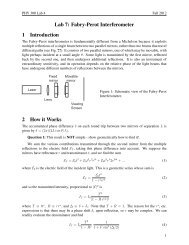
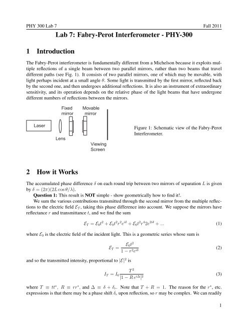
<strong>PHY</strong> <strong>300</strong> <strong>Lab</strong> 7 Fall 2011<strong>Lab</strong> 7: <strong>Fabry</strong>-<strong>Perot</strong> <strong>Interferometer</strong> - <strong>PHY</strong>-<strong>300</strong>1 <strong>Introduction</strong>The <strong>Fabry</strong>-<strong>Perot</strong> interferometer is fundamentally different from a Michelson because <strong>it</strong> explo<strong>it</strong>s multiplereflections of a single beam between two parallel mirrors, rather than two beams that traveldifferent paths (see Fig. 1). It consists of two parallel mirrors, one of which may be movable, w<strong>it</strong>hlight perhaps incident at a small angle θ. Some light is transm<strong>it</strong>ted by the first mirror, reflected backby the second one, and then undergoes add<strong>it</strong>ional reflections. It is also an instrument of extraordinarysens<strong>it</strong>iv<strong>it</strong>y, and <strong>it</strong>s operation depends on the relative phase of the light beams that have undergonedifferent numbers of reflections between the mirrors.FixedmirrorMovablemirrorLaserLensViewingScreenFigure 1: Schematic view of the <strong>Fabry</strong>-<strong>Perot</strong><strong>Interferometer</strong>.2 <strong>How</strong> <strong>it</strong> WorksThe accumulated phase difference δ on each round trip between two mirrors of separation L is givenby δ = (2π)(2L cos θ/λ).Question 1: This result is NOT simple - show geometrically how to find <strong>it</strong>!.We sum the various contributions transm<strong>it</strong>ted through the second mirror from the multiple reflectionsto the electric field E T , taking this phase difference into account. We suppose the mirrors havereflectance r and transm<strong>it</strong>tance t, and we find the sumE T = E 0 t 2 + E 0 t 2 r 2 e iδ + E 0 t 2 r 4 2e 2iδ + ... (1)where E 0 is the electric field of the incident light. This is a geometric series whose sum isand so the transm<strong>it</strong>ted intens<strong>it</strong>y, proportional to |E| 2 isE T = E 0t 21 − r 2 e iδ (2)I T = I 0T 2|1 − R e i∆ | 2 (3)where T ≡ tt ∗ , R ≡ rr ∗ , and ∆ ≡ δ + δ r . Note that T + R = 1. The reason for the r ∗ , etc.expressions is that there may be a phase shift δ r upon reflection, so r may be complex. We can readily1
<strong>PHY</strong> <strong>300</strong> <strong>Lab</strong> 7 Fall 2011evaluate the denominator and findI T = I 0T 21 − R 2 11 + F sin 2 (∆/2)(4)where F ≡ 4R/(1 − R) 2 is called the finesse of the interferometer. Clearly for the resonant case,sin ∆ = 0 ⇒ cav<strong>it</strong>y length is an integer multiple of λ/2 and normal incidence, the transmission is100%, independent of the value of r. For a graph of I T see page 89 of Fowles.Question 2: Derive Eq. 4.This is a most amazing result. If we shine a beam of light on a 99% reflecting mirror, 1% goesthrough and the other 99% is reflected. Yet if we place a second mirror behind the first one, wherethere is only 1% of the light present, somehow 100% of the light appears.Question 3: Can you explain this??? <strong>How</strong> can energy be conserved if the first mirror reflects 99%of the light and yet 100% is transm<strong>it</strong>ted??The ratioI T,max − I T,minI T,min=1/(1 + 0) − 1/(1 + F )1/(1 + F )= 1 − 1/(1 + F )1/(1 + F )= 1 + F − 1 = F (5)tells us that the contrast between max and min is F . Since we can get F as high as 10 6 we canmake really high contrast fringes. At the half-max intens<strong>it</strong>y point where ∆ = ∆ c , we find 1/2 =1/(1 + F sin 2 (∆/2)) so ∆ c = 2/ √ F since ∆ c ≪ 1 and we make the small angle approximation forsin ∆ c . Thus the full width at half max (FWHM) is 4/ √ F .3 ExperimentClearly the way to scan this interferometer to see the variations of transm<strong>it</strong>ted intens<strong>it</strong>y is to move oneof the mirrors w<strong>it</strong>h respect to the other. But <strong>it</strong>’s very hard indeed to do this and keep them parallel, soinstead we’ll use a diverging light beam and observe fringes caused by the variation of θ.The setup will be similar to that of the Michelson interferometer setup, but there will be no beamspl<strong>it</strong>ter.Pos<strong>it</strong>ion the stationary mirror so that <strong>it</strong>s face is parallel to the movable mirror and just a fewmillimeters or so away from <strong>it</strong>. Mount the viewing screen behind the movable mirror. Adjust thestationary mirror until you get just one spot on the screen. Now mount the 18 mm lens on a holderabout 6 cm from the stationary mirror to produce a diverging beam and thus a continuum of values ofθ. You should see clear fringes on the screen. Find the center of the fringe pattern. Project the fringeson a screen far away.Measure the angular sizes of a series of fringes. The theoretical relationship between the orderof the fringe, the wavelength of the light, the angular displacement of the fringe, and the distancebetween the mirrors can be found from the derivation above. Measure the FWHM of the fringes andcompare w<strong>it</strong>h 4/ √ F (find F by measuring the reflection coefficient, or more easily, the transmissioncoefficient) of the mirrors. Discuss the sources of error in this method.2