Tecnoforge-Gas Equipment.pdf - sge.com.sa
Tecnoforge-Gas Equipment.pdf - sge.com.sa
Tecnoforge-Gas Equipment.pdf - sge.com.sa

Create successful ePaper yourself
Turn your PDF publications into a flip-book with our unique Google optimized e-Paper software.
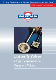
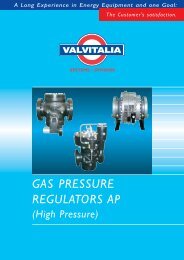
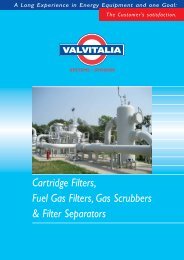
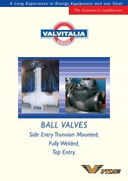
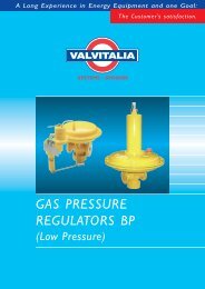
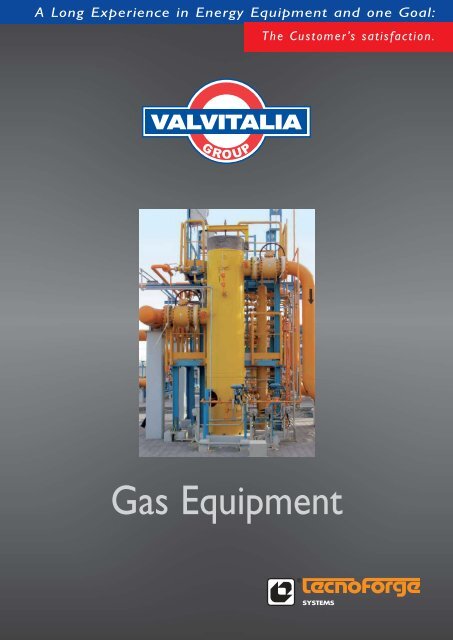
A Long Experience in Energy <strong>Equipment</strong> and one Goal:The Customer’s <strong>sa</strong>tisfaction.<strong>Gas</strong> <strong>Equipment</strong>
VALVITALIA S.p.A. - TECNOFORGESystems Division is a Company dedicating it<strong>sa</strong>ctivity to the design and manufacture ofPressure Vessels for OIL & <strong>Gas</strong> field offering awide range of products like Launching &Receiving Scraper Traps, Filter Separators,Heaters, Conden<strong>sa</strong>te and Drain Tanks, with highdegree of customi<strong>sa</strong>tion and an extremely highstandard of quality and service.The <strong>com</strong>pany’s attainment of prestigiouscertifications underlines a level of overall qualityunmatched in the sector: not just extremelyhigh standards of quality and service, but researchand innovation in terms of technological andmanagement expertise.TECNOFORGE Systems activities includes:developing, design, manufacturing and supplyingof Launching & Receiving Scraper Traps, FilterSeparators, Heaters, Conden<strong>sa</strong>te and DrainTanks;Design codes:● ASME Sec. VIII Div. 1 and 2;● BS;● AD Mehrblatt;● U Stamped;● PED;● Others upon request.TECNOFORGE Systems reserves the right to change design, specification and materials without notice2
Knock-Out DrumVane Mist ExtractorKO-V01KO-C01Models - Production RangeVM-V01VM-D01Operating PrincipleThe extractor consists of a vanes pack formed by a series of parallel plates<strong>com</strong>plete with an intermediate series of hooks. The gas, flowing through thevanes, is forced to change direction several times and the heavier liquiddroplets are then smashed against the wetted walls. The small particles arecoalesced by agitation and surface contact. The agglomerated liquid is thendrained perpendicular to the gas flow into the sump.EfficiencyThe efficiency of this kind of filter i<strong>sa</strong> typical function of particle size anddistribution, particle loading, elementface velocity and pressure drop. Thevane mist extractor is able to removeliquid droplets up to 8 microns andlarger.Cross section KO-DrumTECNOFORGE Systems reserves the right to change design, specification and materials without notice4
Multicyclone FiltersTECNOFORGE Systems has a <strong>com</strong>plete rangeof production of filters:● KO Drum● Cartridge Filters● <strong>Gas</strong> Scrubbers (Multicyclone, Vane Mist extractor)● Dual Stage Filter Separators● Y-Filters● TEE StrainerFiltering efficiency up to 100% for solid and liquidparticles 1 to 50 microns Vertical and Horizontalinstallation.EfficiencyThe efficiency of this kind of filter is a typical functionof particle size and distribution, particle loading,element face velocity and pressure drop. A typicalperformance efficiencyis 100% for solid particlesof 5 microns andlarger and in the dualstage configuration(cyclone and cartridge)is 100% for solid particlesof 3 microns andlarger. In addition theseparator can guaranteean outlet gas withless than 10 liters ofliquid per million cubicmeter.Details of InternalsModels - Production RangeSingle stage - Single cycloneMod. CYC-SSingle stage - Multiple cyclones Mod. CYC-MDual stage - Single cycloneMod. CYC-S-DDual stage - Multiple cyclonesMod. CYC-M-DApplicationsThe cyclone separator is used in a wide range ofapplications in the natural gas and chemical processindustries such as:● Metering and reducing Stations: removing liquidhydrocarbons, water and <strong>sa</strong>nd● Natural <strong>Gas</strong> field application● <strong>Gas</strong> and Fuel transmission lines● Meter Installations● <strong>Gas</strong> <strong>com</strong>pressorsOperating principleThe operating principle of the cyclone filterseparator is based on the action of centrifugal forcesthat separate the solid and liquid parts. The gas,entering into the cyclone, forces the particle<strong>sa</strong>gainst the cyclone walls moving the liquid droplet<strong>sa</strong>nd the solid particles to the outer periphery of thetube and then dropping them into the collectionchamber at the bottom of the vessel. The cleaned gasexits instead to the top of the vessel to theeventual second stage cartridge dry separator toremove the finest solid particles. The cyclone filterseparator could be designed with a single cycloneaction or with a multiple cyclones action in order toraise the efficiency of the process.Cross section Multicyclones Filter5TECNOFORGE Systems reserves the right to change design, specification and materials without notice
Dual-stage FiltersOperating principleThe absolute filter separator is designed to beinstalled in a vertical or in a horizontal configuration,it could be inserted a "quick opening" end closure foraccess to the filter elements. The gas enters the vesseland encounters a labyrinth of pipes that give acentrifugal motion to the particles of 10 micron andabove to the bottom of the filter. Smaller particleswhich exhibit significant brownian movement collidewith each other coalescing to a single droplet.Anelastic collision of solids produce then aggregateswhich subsequently are swept by the liquid into thesump. Particles that remain suspended encounter thefilter coalescer elements and then they collide withand adhere to the fibers or other droplets andcoalesce. This agglomerated liquid is then forcedthrough the media by the drag of the gas for thesecond stage separation. The second stage section,which is the vane mist separator, by changing thedirection of the vapour to generate an increase inapparent density of the liquid phase, trap all the liquiddroplets in the hooks draining the <strong>sa</strong>me into the sump.Filtering CartridgeThe filtering elements are engineered, designed andmanufactured, in a variety of medias, to provide thereliability and consistency in performance. This isneces<strong>sa</strong>ry for the delivery of outstanding operatingefficiency in a wide variety of filtration applications.Our experienced Sales and Application Engineers canassist you in selecting the correct element to solveyour particular filtration problem.Production RangeVertical Type Mod. ABS-VHorizontal Type Mod. ABS-HApplicationsThe absolute filter separator is a multi stageseparator used in a variety of applications in thenatural gas and chemical process industries such as:● Metering and reduction Stations: removing liquidhydrocarbons, water, <strong>sa</strong>nd and pipe scale.● Ahead of gas storage fields to prevent the injectionor withdrawal of solids and liquids.● On the suction side of the <strong>com</strong>pressor to preventwear from solids and liquids entrained in the gasstream.● On a gas processing plants to remove solid andfree liquids in order to prevent fouling of processequipment and poisoning of catalyst beds.● Downstream of amine, glycol, potassium, carbonatesulfinol and absorption oil contactors to recoversolutions and reduce solution losses.EfficiencyThe efficiency of this kind of filter is a typical functionof particle size and distribution, particle loading, elementface velocity and pressure drop. A typical performanceefficiency is 100% for solid particles of 3microns and larger and 99% for particles between0.5-3 micron and 100% for liquid particles of 3microns and larger.TECNOFORGE Systems reserves the right to change design, specification and materials without notice6
Shell and tubesTECNOFORGE Systems has a <strong>com</strong>plete rangeof production of Heaters:● Shell & Tube Heat exchangers;● Performance Heaters● Indirect Water Bath Heaters;● Diathermic Oil Bath Heaters;● Electric Heaters.Heat ExchangerHeat exchangers are designed for heating naturalgas, air, propane and other non aggressive gases. Theyare designed to <strong>com</strong>pen<strong>sa</strong>te the Joule-Thompsoneffect during a gas expansion, in order to avoid thehydrates formation potentially dangerous in gastreatment and reduction station. The workingprinciple is based on heat exchange by conductionbetween the heating fluid (hot water or steam) andthe gas to be expanded. Heat exchangers guaranteea wide exchange surface in order to keep highthermal efficiency.Design advantages● Standard design units are available for a wide rangeof temperatures, pressures and flow rates● Customised features upon customer request● Wide range of materials● Heating fluids: hot water and steam● Low Pressure Loss● Large surface for high thermal efficiency● Low Maintenance costs● No floating parts are inside the equipment, whichwill avoid malfunctions and maintenance costs.Features● Maximum working temperature: up to 300°C● <strong>Gas</strong> nozzle connection: from ANSI 150up to ANSI 900● Water/steam nozzle connection:PN16, ANSI 150,ANSI 300● Power rating: from 7.000 kcal/hup to 5.000.000 kcal/h● Low cost internal inspection: with the inspectablemodel it is possible to check and verify the internalsection of the vessel with a low service cost.7TECNOFORGE Systems reserves the right to change design, specification and materials without notice
Why an indirect HeaterIt is to be found in an economic justification. Thefluid carrying coils are operated at a maximumpressure of 3,000 psi. (depending on the customerrequirements), whereas the shell of the indirectheater containing the heat transfer medium (water)is operated usually at atmospheric pressure, or at avery little pressure above it, therefore it’s required athin wall vessel for the heater shell. In addition, alsothe firetube needs withstand only the atmosphericpressure plus a few pounds. It would be prohibitivefrom several standpoints to attempt to makefiretube to withstand the pressure of 3,000 psi aswell as the heater shell itself; thus the creation of theindirect type heater with fluid carrying high pressurecoils immersed in an atmospheric pressure waterbath heated by a firetube operating close to theatmospheric pressure.<strong>Gas</strong> HeaterWhat is an indirect HeaterAn indirect heater is an oilfield terminology for avessel <strong>com</strong>plete with: a firetube (which is usuallyfired by natural gas), a fluid around the firetube(which is usually water) and, immersed in the fluid,a coil containing the fluid to be heated. The waterbath around the firetube is heated directly by havingcontact with the firetube and the coil containing thefluid to be heated is immersed in this hot water bath.Because there is an intermediate step of heattransfer between firetube and coil, the heater derivesits oilfield terminology of “indirect heater”.Use of the indirect HeaterNormally the natural gas is produced at highpressures ranging from 1,500 psi up to 3,000 psiand it’s usually transferred to <strong>sa</strong>le gas lines thatoperate at 1,200 psi and below. The indirect heateris often employed to supply heat to a gas streamthat is being expanded from some elevated pressure(well head) to some intermediate pressure(intermediate production equipment) or to theactual <strong>sa</strong>le line pressure. Heat supplied is used to<strong>com</strong>pen<strong>sa</strong>te for the Joule-Thompson effect of the gasthrough expansion.TECNOFORGE Systems reserves the right to change design, specification and materials without notice8
A most frequent applicationThe high pressure fluid is introduced to the heatingunit through a choke located at the heater inlet, andthe expansion takes place immediately inside theheater in the water bath. Then, as the fluid passesthrough the steel coils, it’s raised to the desiredoutlet temperature suitable to <strong>com</strong>pen<strong>sa</strong>te theJoule-Thompson effect during the expansion. Thesteel coil, which is subject to the well head operatingpressure, is subject further to corrosion by the fluidcarried within the steel pipe as well as erosioncaused by the high velocity of the fluid itself. In timethe <strong>com</strong>bination of corrosion and erosion takes itstoll in wall thickness of steel pipe.Features AvailableRemovable FiretubeRemovable Tube bundleLarge firetube <strong>com</strong>bustion volume per square footof firetube areaQuality fabricationX-ray and stress relieving facilitiesAutomatic control, regulation and <strong>sa</strong>fety systemssuitable to operate also without electric power.High Performance and High EfficiencyDesigned and manufactured inaccordance to:API 12 KASME VIII9TECNOFORGE Systems reserves the right to change design, specification and materials without notice
LAUNCHING & RECEIVINGSCRAPER TRAPSDescription and featuresValvitalia S.p.A. - TECNOFORGE SystemsDivision, designs and manufactures Launching &Receiving Scraper Traps as stand alone itemsor included in a package with instrumentation,skid mounted and <strong>com</strong>plete with ball valve<strong>sa</strong>nd fittings.Launching & Receiving Scraper Traps includeall devices for internal cleaning, gauging,inspection and all devices for launching orreceiving the scrapers.The scraper traps shall be installed on thepipeline to clean periodically the pipeline, tocontrol the corrosion, to remove the liquidincrease in gas lines, etc.Engineering, Design and Manufacturing ofseveral types of Launching & ReceivingScraper Traps depending on Type of pig:Type:● Sphere● Pigs● Intelligent pigDesign Codes applicable are:● ANSI B31.1; B31.3;B31.4 ; B31.8● ASME VIII Div.1Type of Closure:● ASME Clamp JAW● BLOCK RING● Threaded type● BANDLOCKAccessories:● Barred Tee● Handling device● Jib Crane● Hoist● Pig signallers● Pig traysTECNOFORGE Systems reserves the right to change design, specification and materials without notice10
Figure 5:DN 36”X 42”; Length up to 11.900 mm;Empty Weight up to 4300 KgFigure 5:DN 36”X 42”; Length up to 11.900 mm;Empty Weight up to 4300 KgFigure 8:46”x 42”/ 34”x 30”; Length 6500 mm/4800 mm; Empty Weight 8500 Kg / 4700 KgFigure 9:30”x 34”/ 16”x 20”; Length 9800 mm / 8200 mm; Empty Weight 4400 Kg / 1800 KgLaunching Trap 48"x42" #600 - Empty Weight: 12500 kgTotal length: 5500 mmReceiving Trap 48"x42" #600 - Empty Weight: 14800 kgTotal length: 7500 mm11TECNOFORGE Systems reserves the right to change design, specification and materials without notice
FILTERING UNITSFilters for solid and liquid particles● Filtering efficiency up to 100% for particles3 ÷ 50 microns● Vertical and horizontal installation● Design codes: ASME Sect. VIII Div. 1-2,“U” STAMP, PED● KO drum● Slug catcher● <strong>Gas</strong> scrubber (Cyclone, Vane mist, Multi-cyclone)● Cartridge● Dual stage filter separatorTECNOFORGE Systems reserves the right to change design, specification and materials without notice12
HEATING UNITSHeating systems● Shell & tube (water or steam)● Vertical and horizontal installation● Indirect water bath heater (<strong>Gas</strong> heater)● Electric heaters● Water pump skid with temperaturecontrol system● Steam flow and temperature control system● Design codes: ASME Sect.VIII Div.1-2,“U” Stamp,PED13TECNOFORGE Systems reserves the right to change design, specification and materials without notice
PIPING PRE-FABRICATIONHeating systems● Shell & tube (water or steam)● Vertical and horizontal installation● Indirect water bath heater (<strong>Gas</strong> heater)● Electric heaters● Water pump skid with temperaturecontrol system● Steam flow and temperature control system● Design codes: ASME Sect.VIII Div.1-2,“U” Stamp,PEDTECNOFORGE Systems reserves the right to change design, specification and materials without notice14
15TECNOFORGE Systems reserves the right to change design, specification and materials without notice
A Long Experience in Energy <strong>Equipment</strong> and one Goal:The Customer’s <strong>sa</strong>tisfaction.Castel<strong>sa</strong>ngiovanni PlantValvitalia S.p.A.TECNOFORGE Systems DivisionVia Emilia Pavese, 3829015 Castel<strong>sa</strong>ngiovanni (PC) - ItalyPhone +39.0523.889811Fax +39.0523.889883e-mail: info.tecnoforge@valvitalia.<strong>com</strong>www.valvitalia.<strong>com</strong>Padova PlantValvitalia S.p.A.TGT Tormene <strong>Gas</strong> Technology DivisionVia Campolongo, 9735020 Due Carrare (PD) - ItalyPhone +39.049.9199611Fax +39.049.9125455e-mail: info.tgt@valvitalia.<strong>com</strong>www.valvitalia.<strong>com</strong>VALVITALIA S.p.A.Via Tortona, 69 - 27055 Rivanazzano (PV) ItalyPhone: +39.0383.945911 - Fax: +39.0383.9459962E-mail: info@valvitalia.<strong>com</strong>Web site: www.valvitalia.<strong>com</strong>04.10 - 2000 - TECFOR-GAS.EQUIP.02